Advertisement
Quick Links
Advertisement

Related Manuals for FRENCH FITNESS FF-FSR80


Summary of Contents for FRENCH FITNESS FF-FSR80
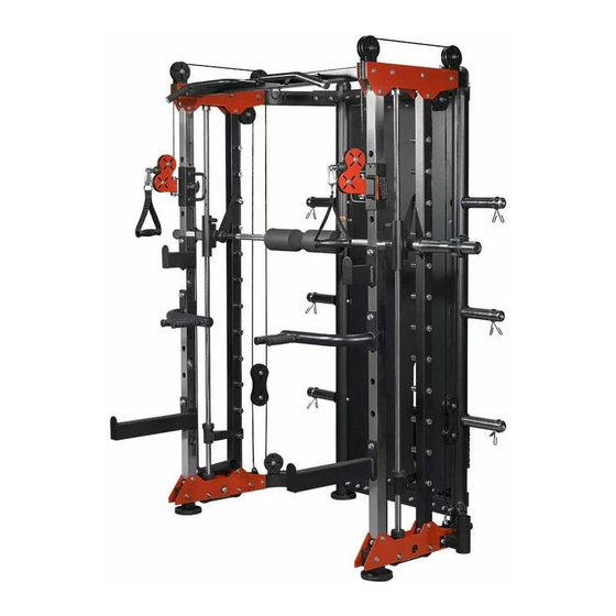
- Page 1 FF-FSR80 FUNCTIONAL TRAINER SMITH & RACK GYM SYSTEM ASSEMBLY MANUAL...
-
Page 2: Warranty
FEATURES • Sealed bearing pulleys • Multi-grip chin up bar with comfortable knurling • 6 weight storage post • High tensile 2000 lbs cables • Adjustable dual pulley system (16 levels) • Smith Machine with 12 adjustable heights. High tension 2000 lb cross cables with 16 adjustable heights. -
Page 3: Parts List
Parts List Specification Part Name Quantity Description Round column left upper welding assembly Assembly part Round column left lower welding assembly Assembly part Round column right lower welding assembly Assembly part Round column right upper welding assembly Assembly part Round column left welding assembly Assembly part Round column right welding assembly Assembly part... - Page 4 Parts List Part Name Specification Quantity Description Smith vibration absorbing washer InnerΦ25 Cross shaft sleeve welding assembly Assembly part Barbell bar Φ30*2200 Smith safety welding assembly Assembly part Guide rod lower retaining assembly Assembly part Weight stack guide rod Φ20*1980 First set of weight stack Assembly part Weight stack...
- Page 5 Parts List Specification Part Name Quantity Description Hexagon nut Guard plate Assembly part Cup head nut M8*30 Washer Φ8 Weight stack placement set Assembly part High pulling handgrip set Assembly part Squat hook left Assembly part Parallel bars set Assembly part Squat safety set Assembly part Squat hook with adjustable foam...
- Page 6 Installation Steps (1) Exploded Drawing Specification Part Name Quantity Description Round column left upper welding assembly Assembly part Round column left lower welding assembly Assembly part Round column right lower welding assembly Assembly part Round column right upper welding assembly Assembly part Round column left welding assembly Assembly part...
- Page 7 Installation Steps (1) Real Drawing after Installation Installation Steps (1) Installation Instructions 1. The Rear weight stack lower welding assembly (8) is installed on the Round column left welding assembly (5) and the Round column right welding assembly (6) by using the Outer Hexagon Bolt (9) and the Flat washer (10).
- Page 8 Installation Steps (2) Exploded Drawing Part Name Specification Description Quantity Outer Hexagon Bolt M10*80 Flat washer Φ10 Locknut Outer Hexagon Bolt M10*90 Upper retaining junction plate Assembly part Lower retaining junction plate Assembly part Upper beam welding assembly Assembly part Dumbbell fly front slideway pipe Stainless steel pipe Smith assembly pipe...
- Page 9 Installation Steps (2) Real Drawing after Installation Installation Steps (2) Installation Instruction 1. The Dumbbell fly slideway welding assembly (18) is installed on The Dumbbell fly front slideway pipe (16) (Pay attention to the direction). 2. The Dumbbell fly front slideway pipe (16) and The Smith assembly pipe (17) are installed on installation steps (1) by using the Outer Hexagon Bolt (9), the Flat washer (10), the Locknut (11), the Upper retaining junction plate (13) and the Lower retaining junction plate (14) (Pay attention to the direction).
- Page 10 Installation Steps (3) Exploded Drawing Part Name Specification Description Quantity Outer Hexagon Bolt M10*80 Flat washer Φ10 Locknut Outer Hexagon Bolt M10*90 Upper retaining junction plate Assembly part Lower retaining junction plate Assembly part Upper beam welding assembly Assembly part Dumbbell fly front slideway pipe Stainless steel pipe Smith assembly pipe...
- Page 11 Installation Steps (3) Real Drawing after Installation Installation Steps (3) Installation Instruction 1. The Guide rod upper retaining assembly (26) is installed on the Upper retaining junction plate (13) by using the Outer Hexagon Bolt (12), the Flat washer (10) and the Locknut (11). 2.
- Page 12 Installation Steps (4) Exploded Drawing Part Name Specification Description Quantity Weight stack guide rod Φ20*1980 First set of weight stack Assembly part Weight stack Assembly part Vibration absorbing washer Inner Φ20 Weight stack base plate Inner Φ20 Locking pipe sleeve Inner Φ20 Magnetic pin Assembly part...
- Page 13 Installation Steps (4) Real Drawing after Installation Installation Steps (4) Installation Instruction 1. The Weight stack guide rod is successively put through the Locking pipe sleeve (38), Weight stack base plate(37)and the Vibration absorbing washer, finally inserted into the hole of weight stack set. 2.
- Page 14 Installation Steps (5) Exploded Drawing Part Name Specification Description Quantity Outer Hexagon Bolt M10*80 Flat washer Φ10 Locknut Outer Hexagon Bolt M10*45 Pulley shell Assembly part Pulley Φ90 Guide roller set of weight stacks Assembly part Weight stack Assembly part Steel rope Assembly part...
- Page 15 Installation Steps (5) Real Drawing after Installation Installation Steps (5) Installation Instruction 1. The headless hexagon socket bolt M8*10 used for connecting the steel rope (45) and the weight stack (44) that is locked is placed into the 75-round pipe. 2. The Guide roller set of weight stacks is installed on the round column by using the outer hexagon bolt (9), washer (10) and locknut (11).
- Page 16 Installation Steps (6) Exploded Drawing Part Name Specification Description Quantity Flat washer Φ10 Locknut Outer Hexagon Bolt M10*90 Outer Hexagon Bolt M10*45 Nylon bush InnerΦ10 Cup head bolt M8*30 Hexagonal head bolt Pulley Φ90 Cable cross handgrip cushion block Assembly part Hexagon locking thread Assembly part Cable cross handle...
- Page 17 Installation Steps (6) Real Drawing after Installation Installation Steps (6) Installation Instruction 1. It is secured on the Round column left upper welding assembly (1) by using outer hexagon bolt (12), washer (10), nylon bush (46), pulley (49) and locknut (11). 2. The hexagon locking thread (51) is secured on the Round column left upper welding assembly (1) by using the Cup head bolt (47).
- Page 18 Installation Steps (7) Exploded Drawing Part Name Specification Description Quantity Flat washer Φ10 Locknut Outer Hexagon Bolt M10*90 Outer Hexagon Bolt M10*45 Nylon bush InnerΦ10 Cup head bolt M8*30 Hexagonal head bolt Pulley Φ90...
- Page 19 Installation Steps (7) Real Drawing after Installation Installation Steps (7) Installation Instruction 1. It is installed on the pulley board by using the outer hexagon bolt (45), the washer (10) and the locknut (40). 2. It is fixed on the Lower retaining junction plate by using the outer hexagon bolt (45), washer (10), nylon bush (46) and locknut (11).
- Page 20 Installation Steps (8) Exploded Drawing Part Name Specification Description Quantity Hexagonal head bolt Cable cross handgrip cushion Assembly part block Hexagon locking thread Assembly part Cable cross handle Assembly part Ground barrel set Assembly part Nylon spacer Inner Φ16 Washer Φ16 Hexagon nut Guard plate...
- Page 21 Installation Steps (8) Real Drawing after Installation Installation Steps (8) Installation Instruction 1. The Weight stack placement set is secured on the round column (both ends are the same) by using the outer hexagon bolt (50), and the washer (51), and the locknut (52). 2.
- Page 22 Installation Steps (9) Exploded Drawing Part Name Specification Description Quantity High pulling handgrip set Assembly part Squat hook left Assembly part Parallel bars set Assembly part Squat safety set Assembly part Squat hook with adjustable foam Assembly part Back-pedal set Assembly part...
- Page 23 Installation Steps (9) Real Drawing after Installation Installation Steps (9) Installation Instruction 1. The High pulling handgrip set (61), the Squat hook left (62), the Parallel bars set (63), the Squat safety set (64), the Squat hook with adjustable foam (65) and the Back-pedal set (66) are mounted on the mainframe.
- Page 24 Product description This multi-function integrated trainer is used to exercise high-low pulling, chest press, du mbbell fly, side pulling by single hand, biceps muscle and triceps muscle training. It can be used for effec tively exercising latissimus dorsi, deltoid, biceps muscle and triceps muscle, Pectoral muscles and leg mus cles.
Need help?
Do you have a question about the FF-FSR80 and is the answer not in the manual?
Questions and answers