
Related Manuals for rada 425-t3


Summary of Contents for rada 425-t3
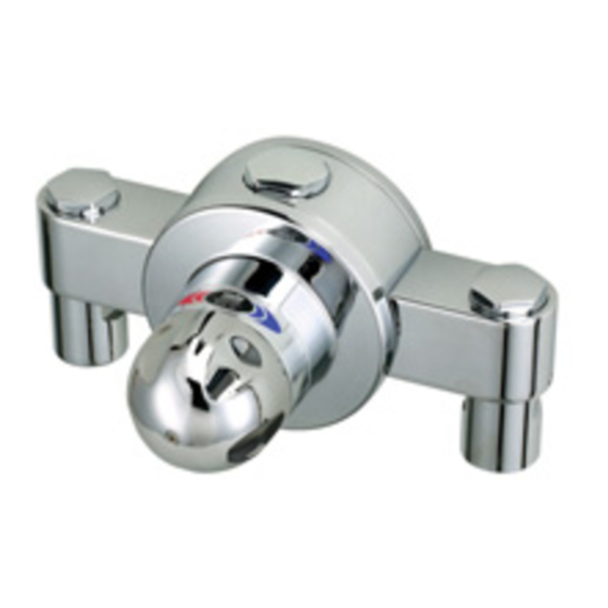
- Page 1 PRODUCT MANUAL IMPORTANT Installer: This Manual is the property of the customer and must be retained with the product for maintenance and operational purposes.
- Page 2 INDEX Page SAFETY WARNINGS ADVICE INTRODUCTION DESCRIPTION PACK CONTENTS DIMENSIONS SPECIFICATION INSTALLATION COMMISSIONING OPERATION FAULT DIAGNOSIS MAINTENANCE SPARE PARTS CUSTOMER CARE Back Cover If you experience any difficulty with the installation or operation of your new mixing valve, then please refer to the Fault Diagnosis section, before contacting Kohler Mira Limited.
-
Page 3: Safety Warnings
SAFETY : WARNINGS The function of this thermostatic mixing valve is to deliver water consistently at a safe temperature. This requires that: It is installed, commissioned, operated and maintained in accordance with the recommendations given in this Manual. Type 3 valves are only used for applications covered by their approved designations. - Page 4 INTRODUCTION The Rada 425-t3 Thermostatic mixing valve is specified to meet the highest standards of safety, comfort and economy as demanded by todays users. The Rada 425-t3 is designed, manufactured and supported in accordance with accredited BS EN ISO 9001:1994 Quality Systems.
-
Page 5: Pack Contents
PACK CONTENTS Tick the appropriate boxes to familiarize yourself with the part names and to confirm that the parts are included. 1 x 425-t3 Mixing Valve 3 x Compression Fittings 3 x Olives 3 x Compression Nuts 4 x Fixing Screws... - Page 6 DIMENSIONS All dimensions are nominal and in mm 200 mm 300 mm 246 mm 56 mm 144 mm 150 mm 73.5 mm...
-
Page 7: Specification
SPECIFICATION Normal Operating Conditions are considered as: - inlet dynamic pressures nominally balanced to within 10% of each other during flow. - a differential of approximately 50 C between the hot and cold inlet temperatures, and with differentials of 15-35 C between the blend setting and either supply. - Page 8 Pressure Loss Ratio is determined by subtracting the resistance of the outlet pipework and outlet fittings from the dynamic pressures of the hot and cold water at the inlets of the mixing valve. This is at its extreme when the mixing valve is used at its lowest flow-rate and when the maximum inequality occurs in the pressure of the hot and cold water supplies.
-
Page 9: Flow Control
Flow Control The Rada 425-t3 mixing valve does not have integral flow control, appropriate provision must be made for this in the outlet pipework. This can be in the form of basin/bath tap, stop-cock, mechanical timed-flow controller or solenoid. The device chosen must be non-concussive in operation. -
Page 10: Installation
Outlet Position/Reversed Inlets The Rada 425-t3 c mixing valve is supplied with the inlet connections configured hot - left, cold - right, and top outlet as standard. Should the existing hot and cold pipework make this configuration inconvenient... - Page 11 Installation The Rada 425-t3 c has easily adjustable inlet elbows to accommodate rising or falling supplies. When unpacked, the inlet elbows are positioned to accept falling supplies. Should the installation require rising supplies then the inlet elbows will need adjusting.
- Page 12 Inlet Pipework Outlet Compression Pipework Inlet Pipework Wall Plugs Fixing Screws Olive Fitting Isolation Screw Backplate Grub Screw Isolator Assembly 2 x Isolator Assembly 2 x Grub Screws Grub Screws (for removal of inlet elbow) Installation Figure 1...
-
Page 13: Exercising The Thermostat
The maximum blend temperature obtainable by the user should be limited, to prevent accidental selection of a temperature which is too hot. All Rada Thermostatic mixing valves are fully performance tested individually and the maximum temperature is pre-set to approximately 45 C under ideal installation conditions at the factory. - Page 14 For Adjustable Temperature Remove the temperature knob concealing cap and then the screw using the 3 mm hexagonal wrench.(refer to Figure 2). Pull off the hub. Note! Leave the pressure washer in place on spindle. Invert the hub and use to rotate the spindle until required maximum blend temperature is obtained at discharge point;...
-
Page 15: Commissioning Checks
Temperature Knob Screw Concealing Cap Stop Lugs Note position of brass stop Commissioning - Adjustable Temperature Setting Figure 2 Temperature Knob Screw Concealing Cap Stop Lugs Commissioning - Locked Temperature Setting Figure 3 Commissioning Checks (Temperatures should always be recorded with a thermometer with proven accuracy). Check inlet pipework temperatures for correct function of checkvalves i.e. -
Page 16: Operation
Operate the outlet flow control and check: (a) Flow rate is sufficient for the purpose (b) Temperature(s) obtainable are acceptable. It is advisable to establish a performance check at this time, which should be noted for future reference as part of a Planned Maintenance Programme. The procedure should be chosen to imitate both typical and difficult operating conditions, such as any supply pressure fluctuations that may be likely. -
Page 17: Fault Diagnosis
FAULT DIAGNOSIS Symptom Cause/Rectification a. Inlet supplies reversed (i.e. hot supply to cold inlet). 1. Only hot or cold Check. water from outlet. b. No hot water reaching mixing valve. Check c. Check filters and inlet fittings for blockage. d. Refer symptom 5 below. e. - Page 18 Symptom Cause/Rectification (Continued) 6. Maximum blend a. Indicates incorrect temperature setting; refer to t e m p e r a t u r e COMMISSIONING. setting too hot or b. As symptom 4 above. too cool. c. As symptom 5 above. 7.
-
Page 19: Maintenance
As with all other thermostatic mixing valves, the critical sensing element in the Rada 425-t3 c together with other “critical components” (table 1) will exhibit wear over a period of time and usage. - Page 20 The designed minimum service life of all these “critical components” is 5 years providing the Rada 425-t3 c is operated with the recommended operating conditions and within the recommended operating parameters. However, when supply conditions and/or usage patterns do not conform to the recommended operating parameters and/or the recommended operating conditions, the thermostatic unit and other critical parts may need to be replaced more frequently (‘recommended...
-
Page 21: Performance Check
Critical Components Figure 4 Performance Check Six Monthly Exercising the Thermostat: If the valve has not been in regular or recent use the thermostat should be exercised before any other checking. Where user adjustment of the blend temperature is available the exercising of the thermostat can be achieved as described in COMMISSIONING. -
Page 22: Service Contracts
To ensure your Rada/Mira products function correctly and give continued safe performance Service Contracts can be undertaken (subject to site survey). All Service Contract work is carried out by fully trained Rada/Mira Service Engineers who carry a comprehensive range of genuine spare parts. -
Page 23: Maintenance Procedures
Components are precision-made, so care must be taken while servicing to avoid damage. When ordering spare parts, please state product type, i.e. Rada 425-t3 c, and identify part name and number (refer to PARTS LIST). A Seal pack is available, containing all the seals that may be necessary for renewal during maintenance or servicing. - Page 24 Maintenance Procedure - Thermostat Assembly Removal (refer to Figure 5) Turn the isolation screw on the isolator valves through 90 to isolate the water supplies to the mixing valve . Open an outlet fitting to release pressure and to assist the draining of residual water. Remove the temperature knob concealing cap and then the screw using the 3 mm hexagonal wrench (supplied).
-
Page 25: Maintenance Procedure
Cleaning/Renewal of Parts The interior surface of the mixing valve body must be clean before refitting the thermostat assembly. Rinse the valve interior thoroughly in clean water to remove any debris before refitting the thermostat assembly. Note! The body interior must be cleaned carefully and not damaged in any way. Do not use any abrasive material. - Page 26 Remove the thermostat assembly Remove the four screws. Insert a bar (maximum 6 mm diameter) through the holes provided at the front of the port sleeve and use this with a slight twisting action to carefully pull the shuttle and sleeve assembly out of the valve body. 10.
- Page 27 Port Sleeve Shuttle Screens Return Spring Retaining Cap Shuttle Seat Overload Spring Port Sleeve Assembly Shuttle and Sleeve Assembly (Disassembled) Figure 7 Cleaning/Renewal of Parts 13. Internal parts (with the exception of the Thermostat Assembly) can be cleaned using a mild proprietary inhibited scale solvent e.g. domestic kettle descalent. After descaling, always rinse parts throughly in clean water before refitting.
- Page 28 Re-assembly 18. Insert the shuttle fully into the port sleeve (wider open end) with radius centre face inwards (refer to Figure 8), ensuring that the separator seal remains in place and is not damaged. 19. Insert shuttle seat into the port sleeve, ensuring that the cut-outs locate into the webs in the shuttle.
- Page 29 Maintenance Procedure - Check Valve Cartridges Hot water entering the cold supply, or vice versa, indicates that immediate attention is necessary. This is carried out by removing and cleaning, or renewing as necessary, the two check valves. Turn the isolation screw on the isolator assemblies through 90 (refer to Figure 9) to isolate the water supplies to the valve.
- Page 30 It is essential that the inlet filters are cleaned or, if necessary, renewed as part of the six-monthly maintenance operations. Caution! Do not operate the Rada 425-t3 c without filters. Product damage may occur. A filter pack is available containing two strainer screens and all the seals which may be needed during filter inspection.
- Page 31 Recommended Content of Maintenance Log It is recommended that the Maintenance Log should record the following: Details of valve, location and use, risk level and instructions Valve make and model Valve unique identification number Valve location Date installed Application i.e. type of discharge: bath, shower etc. Risk assessment report number Risk level found (e.g.
- Page 32 Start 1. Measure & record supply temperature and pressures, if possible (See Commissioning). Are critical 2. If valve not in recent use exercise thermostat. components due (See Commissioning) for replacement? 3. Measure & record blend temperature & flow rate @ maximum flow (See Commissioning). 4.
- Page 33 Note! K = Kelvin, the unit of thermodynamic temperature. The unit "Kelvin" is equal to the unit of "Degree Celsius". Kelvin is used for a difference of Celsius temperature. Guide to In-service Test Frequency Figure 12...
- Page 34 Low Pressure † Mixed water temperature at discharge point. = Rada 425-t3 approved designations. Note! For washbasins, it is assumed that you are washing under running water. Note! Bath fill temperatures of more than 44°C should only be available when the bather is always under the supervision of a competent person (e.g.
-
Page 35: Installation Conditions
In order to achieve the safe water temperatures expected of a Type 3 valve it is essential that the valve is used only for the applications covered by its approved designations, with the appropriate water supply pressures and temperatures, and it is commissioned, maintained and serviced in accordance with the recommendations contained in this guide. - Page 36 Adjust the temperature of the mixed water in accordance with the instructions in this manual and the requirement of the application and then carry out the following sequence: (a) record the temperature, and pressures if possible, of the hot and cold water supplies.
- Page 37 SPARE PARTS...
-
Page 38: Spare Parts List
SPARE PARTS Spare Parts List 414.92 Knob Pack 523.01 Backplate Pack 523.02 Drain Plug 523.03 Cover 523.04 Cover Shroud 523.05 Hub Pack 523.06 Thermostat Pack - components identified ‘A’ 523.07 Drive Mechanism Pack - components identified ‘B’ 523.08 Port Sleeve Pack - components identified ‘C’ 523.09 Shuttle Pack - components identified ‘D’... -
Page 39: Spare Parts Diagram
Spare Parts Diagram 523.03 B, G 523.05 523.04 523.01 414.92 523.02 C, D 523.15 523.14 C, D H, J C, G 523.16 H, J F, J 523.18 523.19... -
Page 40: Customer Care
Rada equipment. Spare Parts All functional parts of Rada products are kept for up to ten years from the date of final manufacture. If during that period, our stock of a particular part is exhausted we will, as an alternative, provide an equivalent new product or part at a price equating to the cost of repair to the old, bearing in mind the age of the product.
Need help?
Do you have a question about the 425-t3 and is the answer not in the manual?
Questions and answers