
Related Manuals for rada Safetherm


Summary of Contents for rada Safetherm
- Page 1 Safetherm PRODUCT MANUAL IMPORTANT Installer: This manual is the property of the customer and must be retained with the product for maintenance and operational purposes.
-
Page 2: Table Of Contents
CONTENTS Introduction ..................... 3 Safety : Warnings ..................3 Pack Contents Checklist ................ 5 Specifications ..................7 Pressures ..................... 7 Temperatures ..................7 Thermostatic Shut-down ..............8 Connections ..................8 Important Points ................... 8 Dimensions ..................10 Installation ..................... 11 Panel Mounting .................. -
Page 3: Introduction
The Safetherm also includes checkvalves, filters and inlet flow regulators limiting the outlet flow to 8 L/Min. The Rada Safetherm has been certified for use in UK Healthcare premises as a Type 3 valve under the BUILDCERT TMV3 scheme. For Healthcare* installations refer to the TMV3 Requirements Manual. - Page 4 This is particularly important in such healthcare procedures as supervised bathing of patients unable to respond immediately to unsafe temperatures. Safetherm Options The following table indicates temperature control options available for the Safetherm.
-
Page 5: Pack Contents Checklist
2 x Olives 2 x 'O' Seals 2 x Inlet Connector 1 x Flat Face Connector Pack 2 x Concealing Shroud 1 x Safetherm Tap Control (Panel Mount) 1 x TMV3 Requirements Manual... - Page 6 1 x 2.5 mm A/F Hexagon Wrench 1 x 3 mm A/F Hexagon Wrench 1 x ‘O’ Key 1 x Safetherm Tap Control (Basin Mount) 1 x Flat Face Connector Pack 2 x Extension Tube ...
-
Page 7: Specifications
SPECIFICATIONS For Type 3 Valves, the supply conditions specified in the TMV3 Requirements Manual take precedence over the operating parameters which follow. Pressures • Max Static Pressure: 10 Bar. • Max Maintained Pressure: 5 Bar. • Min Maintained Pressure (Gravity System): 0.1 Bar. (0.1 bar = 1 Metre head from cold tank base to tap outlet). -
Page 8: Thermostatic Shut-Down
Installations must comply with all Local/National Water Supply Authority Regulations/Bye-laws, and Building and Plumbing (UK:BS6700) Regulations. Rada products are precision engineered and should give continued and superior performance, provided: They are installed, commissioned, operated and maintained in... - Page 9 Note! the use of ammonia or any ammonia type chemicals ( e.g. as found in some solder fluxes) can attack brass material which may lead to premature failure. If in any doubt as to the suitability of chemical solutions, contact Kohler Mira Ltd or your local agent.
-
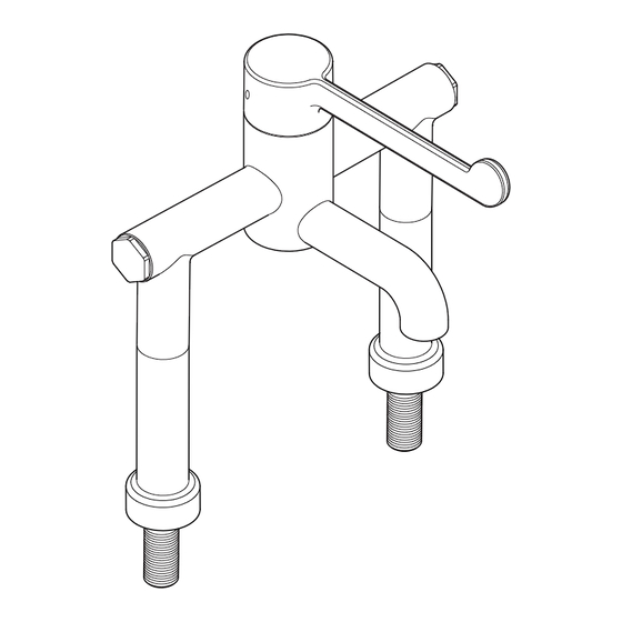
Page 10: Dimensions
Dimensions Ø 42 131.5 1/2” BSP 131.5 Ø 60 1/2” BSP All dimensions are nominal and in millimetres... -
Page 11: Installation
Layout and sizing of pipework MUST be such that nominally equal inlet supply pressures are achieved and effects of other draw-offs are minimised. The Rada Safetherm is suitable for installation as part of a gravity-fed plumbing system. Minimum inlet pressures of 0.1 bar (1 metre head) are required, though inlet pressures of 1 bar (10 metre head) are recommended for optimum performance. -
Page 12: Panel Mounting
Panel Mounting Warning! Make sure that there are no buried cables or pipes in the wall before drilling. 2.5 mm Hexagonal 'O' Seal Temporarily assemble the inlet connectors with the inlet elbows tightening both grubscrews with a 2.5 mm hexagonal key. Grubscrew Inlet Connector... - Page 13 Turn the isolators to the OFF position then turn on the water supply and check for leaks. Heat Note! The isolation valve is located Shroud in the body of the inlet connector. To isolate the water supply, turn the screw slot on the isolation valve a quarter turn.
-
Page 14: Basin Mounting
Basin Mounting Deck Mount Plate Slide the 'O' seal along the threaded 'O' Seal section of the inlet connector then screw the inlet connector and the deck mount plate together. Inlet Connector Insert the inlet connectors through the basin holes. Fit the large rubber washers and back Inlet Connector plates then loosely fit the back nuts. - Page 15 Fit the deck mount rings over the inlet The access window connectors. of the heat shroud must align with the isolation valve. Fit the heat shrouds to the inlet connectors. Note! The access window of the heat shroud must align with the isolation valve. Screw the elbow extensions onto the inlet connectors and tighten with a 10 mm hexagonal key.
-
Page 16: Operation
OPERATION Rada Safetherm uses a single sequential control lever for on/off and temperature control. The control lever operates anti-clockwise in the following sequence: • • • Cool • Warm • Maximum Preset Temperature 30° 120° Maximum Preset... -
Page 17: Commissioning
COMMISSIONING Commissioning must be carried out in accordance with these instructions, and must be conducted by designated, qualified and competent personnel. Exercising the Thermostat Thermostatic mixing valves with wax thermostats are inclined to lose their responsiveness if not used. Valves which have been in storage, installed but not commissioned, or simply not used for some time should be exercised before setting the maximum temperature or carrying out any tests. - Page 18 Carefully remove the concealing cap, unscrew the grubscrew using a 2.5 mm hexagonal key (supplied) and pull off the control lever. Unscrew the hub retaining screw with a 2.5 mm hexagon key. Note! Do not remove the hub. Insert the 2.5 mm hexagon key into the centre of the spindle and engage with the recessed temperature adjusting screw.
-
Page 19: Fault Diagnosis
FAULT DIAGNOSIS Symptom Cause/Rectification Only hot or cold Inlet supplies reversed. Check. water from tap No hot water reaching control. Check. outlet. Check filters and inlet fittings for blockage. Installation conditions continuously outside operating parameters: refer to the section: 'SPECIFICATIONS' and symptom 2.e. - Page 20 Symptom Cause/Rectification M a x i m u m Indicates incorrect maximum temperature setting; refer b l e n d to the section: 'COMMISSIONING'. temperature As symptom 4. setting too hot As symptom 5. or too cool. Water leaking Seal(s) worn or damaged. from control Obtain service pack and renew all seals.
-
Page 21: Maintenance
MAINTENANCE Planned Maintenance Malfunction of Thermostatic Mixing Valves is almost always progressive in nature and will be detected by the use of proper temperature checking and maintenance routines. Certain types of system can result in the valve having excessive ‘dead-legs’ of pipework, or auxiliary cold water supply added to the mixed water from the valve. -
Page 22: Thermostatic Cartridge Renewal
Thermostatic Cartridge Renewal Control Concealing Important! Use only silicone-based lubricants Lever when reassembling. Isolate the water supplies using the ball Grubscrew valves fitted in the inlet connectors. Turn on the control lever to relieve Bearing water pressure and to drain any residual water. -
Page 23: Filter Renewal
Filter Renewal Should the filters require cleaning or renewal then the following procedure should be followed (refer to the following illustration). Important! Use only silicone-based lubricants when reassembling. Isolate the water supplies using the ball valves fitted in the inlet connectors and operate the lever to drain the tap control of any residual water. -
Page 24: Checkvalve Cartridge Renewal
Checkvalve Cartridge Renewal Isolate the water supplies using the ball valves fitted in the inlet connectors and operate the lever to drain any residual water. Use a 2.5 mm hexagonal key to loosen the grubscrews and release the main tap control body from the inlet connectors. Remove the tap control. -
Page 25: Spare Parts
SPARE PARTS Safetherm Spare Parts Diagram (Panel Mount) 1704.193 Screw Pack - Identified A 1704.181 1704.194 Lever and Seal Pack - Identified B Bearing 1704.228 Isolator 1704.225 Cold Elbow Hex Assembly 1704.180 1704.179 Cartridge Assembly 1704.227 Panel Shroud Screw 1704.186... - Page 26 Safetherm Spare Parts Diagram (Basin Mount) 1704.181 Lever and 1704.193 Bearing Screw Pack - Identified A 1704.194 Seal Pack - Identified B 1704.225 1704.179 Cold Elbow Hex Cartridge Assembly Assembly 1704.185 Checkvalve 1704.184 Filter 1704.224 Hex Filter Plug 1704.186 Flow 1704.226...
-
Page 27: Notes
NOTES... -
Page 28: Customer Care
CUSTOMER SERVICE CUSTOMER CARE Guarantee of Quality Rada Customer Service Rada products have the benefi t of our one year Technical Helpdesk Service manufacturer’s guarantee which starts from the date of dedicated Customer Services Team purchase. comprehensively trained and can offer help and advice, Within the guarantee period we will resolve defects in spare parts, accessories or a service visit. - Page 29 Check out our full range of Bathroom Taps Contemporary Bathroom Taps Traditional Bathroom Taps Waterfall Bathroom Taps Basin Taps Bath Taps Bidet Taps Luxury Mira Aspects Taps Mira Honesty Mira Evolve Mira Precision Mira Comfort Mira Revive Mira Fluency Don’t forget these amazing tap cleaning and care products Cramer Tap Cleaner Cramer Chrom Star Chrome Polish...
Need help?
Do you have a question about the Safetherm and is the answer not in the manual?
Questions and answers