Table of Contents
Advertisement
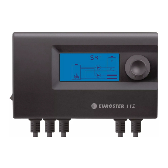
EUROSTER 11Z – USER MANUAL
MANUFACTURER: P.H.P.U. AS, ul. Polanka 8a/3, 61-131 Poznań
1. INTRODUCTION
In order to guarantee correct operation of central heating and hot usable water controller and
installations one should familiarize oneself with the present user manual.
2. INTENDED USE
EUROSTER 11Z is a modern controller that independently controls operation of two pumps:
central heating circulating pump and hot water tank loading pump with the possibility of
prioritizing hot water pump.
The controller switches off central heating pump if temperature of the heating boiler falls below
a predefined value.
If tank temperature falls down, tank loading pump will be switched off. Moreover, the controller
protects the tank against cooling down in case of low temperature of boiler extinction. Hot
water priority function allows for the fastest possible way of heating the tank.
3. CONTROLLER FUNCTION
•
prevents boiler sweat
•
keep constant temperature in the tank
•
switches on the hot water priority function
•
blocking function against tank cool down
•
anti-stop function to protect pumps against stoppage
•
frost protection
•
pump operation test
•
temperature reading correction
The EUROSTER 11Z controller has been equipped in an ANTY STOP system to prevent seizing
of rotors of unused pumps. After finishing heating season it automatically launches the pumps
for 30 seconds every 14 days. In order for the system to work out of season, the controller
must be left on.
EUROSTER 11Z
Operation and assembly manual
version of the manual 01.05.2013
1
Advertisement
Table of Contents

Related Manuals for EUROSTER 11Z


Summary of Contents for EUROSTER 11Z
- Page 1 • temperature reading correction The EUROSTER 11Z controller has been equipped in an ANTY STOP system to prevent seizing of rotors of unused pumps. After finishing heating season it automatically launches the pumps for 30 seconds every 14 days. In order for the system to work out of season, the controller...
- Page 2 EUROSTER 11Z – USER MANUAL 4. EXTERNAL VIEW 1. Controller power supply cable, 230 V, 50 Hz 2. Power supply cable for the central heating pump, 230 V 50 Hz 3. Power supply cable for the tank loading pump, 230 V 50 Hz 4.
- Page 3 EUROSTER 11Z – USER MANUAL 6. SCREEN DESCRIPTION Active LCD screen elements have been presented below: Names of the set parameter - displayed during setting monitoring or changing Heat source (boiler) temperature sensor symbol Test operation symbol - on during tests...
- Page 4 EUROSTER 11Z – USER MANUAL 8. RESTORING FACTORY SETTINGS / PERMANENT SCREEN LIGHT-UP If it is needed to restore factory settings, the following steps should be taken: • Keep the knob pressed and turn the controller on and off. "Fd" (Factory defaults) will appear on the screen, once the knob is released, 0 will appear.
- Page 5 EUROSTER 11Z – USER MANUAL 8. Reading correction - tank temperature This is the value which is added or deduced from the measured temperature. it allows for correction of temperature difference between the sensor placed on the pipe and water temperature.
- Page 6 Knob works in an unforeseeable manner Pulse generator damage - send device to service. 13. NORMS AND CERTIFICATES The EUROSTER 11Z controller conforms with UE directives: EMC and LVD. CE conformity declaration has been published and made available at: http://www.euroster.com.pl...
- Page 7 EUROSTER 11Z – USER MANUAL 14. TECHNICAL DATA Controlled device central heating pump and hot water pump Supply voltage 230 V 50 Hz Maximum inlet and outlet load 3 A 230 V 50 Hz Maximum power consumption 1.6 W Temperature measurement range from -5ºC to +120ºC...
- Page 8 EUROSTER 11Z – USER MANUAL 17. CONNECTION SCHEME The scheme presented is simplified and does not include all the elements necessary for correct installation operation. In an installation with central heating and hot water pumps 1. EUROSTER 11Z controller 2. Hot water tank temperature sensor 3.
Need help?
Do you have a question about the 11Z and is the answer not in the manual?
Questions and answers