Table of Contents
Advertisement
Quick Links
EUROSTER 10PC – INSTALLATION AND OPERATION MANUAL 1
CH PUMP CONTROLLER FEATURING HEATING SOURCE CONTROL
MANUFACTURER: P.H.P.U. AS, Chumiętki 4, 63-840 Krobia, Poland
1. INTRODUCTION
In order to ensure proper operation of the controller and the CH system, please read this
manual carefully.
2. APPLICATION
EUROSTER 10PC is designed to control the CH circulating pump and to switch on the
heating source (voltage-free contact). The controller is equipped with an input to connect
a room thermostat and two temperature sensors (one for the heating source and one for
the heating zone).
The controller may be used in the following systems:
•
With a heat pump, to control the CH pump with a buffer tank
•
Floor heating equipped with a thermostatic mixing valve
•
Heating systems, to switch on the CH pump with an activation temperature
3. CONTROLLER FUNCTIONS
•
Controls a CH circulating pump
•
Controls a heating source
•
Cooperates with a room thermostat
•
Protects the heating system against overheating – a preset alarm temperature for
a heating zone and supply
•
Measures the heating source temperature
•
Features a function that protects the system against freezing
•
Prevents seizure of the pump – Anti–Stop function
•
set of sensors included
•
Installation in an electric cabinet (6 modules) on a DIN 35 mm rail.
EUROSTER 10PC controller is equipped with an Anti-Stop system that prevents the process
of scale build-up on the unused pump rotor. It automatically turns the pump on every
14 days when the heating season is over. Keep the controller turned on to allow the function
to operate after the heating season.
EUROSTER 10PC
Manual version: 01.08.2023
Advertisement
Table of Contents

Related Manuals for EUROSTER 10PC


Summary of Contents for EUROSTER 10PC
- Page 1 2. APPLICATION EUROSTER 10PC is designed to control the CH circulating pump and to switch on the heating source (voltage-free contact). The controller is equipped with an input to connect a room thermostat and two temperature sensors (one for the heating source and one for the heating zone).
- Page 2 EUROSTER 10PC – INSTALLATION AND OPERATION MANUAL 2 4. VISIBLE ELEMENTS OF THE CONTROLLER 1. Controller’s power connection – 230 V 50 Hz 2. Output for connecting the CH pump 230 V 50 Hz 3. Output for connecting heating source (change-over voltage-free contact) 4.
- Page 3 PE conductors. The temperature sensors are not suitable to be immersed in liquids. CAUTION! Euroster 10PC controller and a heat emitting device connected to the “Boiler” output must be powered from the same phase of the power system. a) Connection Diagram...
- Page 4 Most commonly, boilers are equipped with the normally open connection (a jumper must be removed from the heating source), in such cases, you need to connect the 10PC controller with COM and NO terminals (the controller has the COM and NO ter- minals).
-
Page 5: Mounting Template
EUROSTER 10PC – INSTALLATION AND OPERATION MANUAL 5 6. MOUNTING TEMPLATE The following diagram is simplified and does not cover all the elements necessary for the correct operation of the system. EUROSTER 10PC Controller Heating zone, e.g. floor heating Heating zone temperature sensor... -
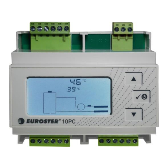
Page 6: Display Description
EUROSTER 10PC – INSTALLATION AND OPERATION MANUAL 6 8. DISPLAY DESCRIPTION Active elements of the display are presented below: Name of the set parameter – displayed while previewing or changing param- eters Heating source (boiler) temperature sensor icon Test operation icon – displayed during manual control Alarm icon –... - Page 7 EUROSTER 10PC – INSTALLATION AND OPERATION MANUAL 7 blinking), set the required value using , and confirm the selection by pressing √. If the current value is to remain unchanged (cancelling changes), do not press the button, but wait 10 seconds until the setting stops blinking.
-
Page 8: Controller Operation
EUROSTER 10PC – INSTALLATION AND OPERATION MANUAL 8 8. Pump Operation/Test Displays the current status of the pump calculated by the controller (0 or 1). To operate the pump manually press the button and change the displayed value. After 10 seconds of inactivity or pressing the knob again, the controller resumes operation according to the settings. -
Page 9: Operation With Room Thermostat
16. SIMPLIFIED DECLARATION OF EU CONFORMITY P.H.P.U. AS AGNIESZKA SZYMAŃSKA-KACZYŃSKA hereby declares that the type of EU- ROSTER 10PC equipment conforms to the following directives: 2014/35/EU (LVD), 2014/30/EU (EMC), 2011/65/EU (RoHS). The complete text of the Declaration of EU conformity is available at the following Internet address: www.euroster.pl. -
Page 10: Kit Contents
EUROSTER 10PC – INSTALLATION AND OPERATION MANUAL 10 18. KIT CONTENTS b) Euroster 10PC Controller c) Controller power cable: 2 m d) Heating zone temperature sensor: 3 m e) Heating source temperature sensor: 3 m Sensor hose clips: 2 pcs. -
Page 11: Warranty Certificate
EUROSTER 10PC – INSTALLATION AND OPERATION MANUAL 11 WARRANTY CERTIFICATE EUROSTER 10PC CONTROLLER Warranty terms: 1. The warranty is valid for 24 months from the device's sale date. 2. The claimed module along with this warranty certificate must be supplied to the seller.
Need help?
Do you have a question about the 10PC and is the answer not in the manual?
Questions and answers