Advertisement
Technical specifications
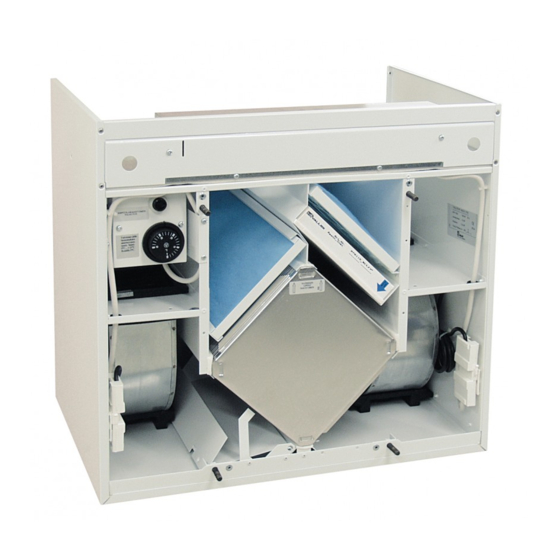
Fans
Fans
Heat recovery
Heat recovery bypass
Post-heating
Filters
Weight
Service switch
Power adjustment
Input power and data
© VALLOX • We reserve the right to make changes without prior notification.
Supply air
VALLOX 75
105 W
Extract air
105 W
Supply air
180 W
VALLOX 95
Extract air
180 W
Plate heat exchanger, efficiency approx. 60%
Summer / winter damper
Electric 500 W radiator or water radiator (VKL)
Supply air
G 3 + F 7
Extract air
G 3
36 kg
Door switch
Cooker hood PTX / PTXP, control centre 1992A/1992A EK
or remote monitoring control centre 1993A YK
230 V, IP 34
Models:
VALLOX 75
VALLOX 75 VKL
• For dwelling-specific ventilation for detached houses,
terraced houses and blocks of flats
• Supply and extract air ventilation with heat recovery
• Silent operation
• Good filtering
• In-built heat recovery bypass for summer ventilation
• Versatile control options
• Handy ceiling mounting plate – for simple and quick
mounting
• Service switch as standard
All models are available as R and L models
65 dm
/s
90 Pa
3
75 dm
/s 130 Pa
3
85 dm
3
/s
75 Pa
95 dm
/s 130 Pa
3
• 1.09.259E
• 22.7.2007
• CODE 3510
© VALLOX
CODE 3510
VALLOX 95
VALLOX 95 VKL
Advertisement
Table of Contents

Related Manuals for Vallox 75


Summary of Contents for Vallox 75
- Page 1 Service switch Cooker hood PTX / PTXP, control centre 1992A/1992A EK Power adjustment or remote monitoring control centre 1993A YK 230 V, IP 34 Input power and data © VALLOX • We reserve the right to make changes without prior notification.
- Page 2 VALLOX 75/95 DIMENSIONS, PERFORMANCE Dimensions and Air volumes and SFP duct outlets VALLOX 75/fan 105 W Fan curves SD and ED are examples of pressure E = Extract air curve losses in supply and extract ducts S = Supply air curve...
- Page 3 VALLOX 75/95 SOUND VALUES AND POWER – 75/95 Measuring points Sound values VALLOX 75, 105 W fan VALLOX 75/ VALLOX 95 Sound power level from the ventilation unit Sound power level from the ventilation unit Measuring points after to supply air ducts by octave band L...
-
Page 4: Control Methods
HEAT RECOVERY BYPASS In winter use the heat recovery cell of VALLOX 75 and VALLOX 95 recovers heat from the air leaving the dwelling and uses it to heat the air coming from the outside. In summer use the heat recovery cell is bypassed in VALLOX 75 and VALLOX 95 with anin- built damper. - Page 5 The threshold temperature of the risk of freezing can be set at the thermostat (J) of the water radiator. Though VALLOX 75/95 VKL units incorporate efficient freezing protection, at least detached houses should be equipped with a separate heating circuit, with a water-glycol mixture (or other non-freezing solution) as the heat transfer fluid.
-
Page 6: Maintenance Instructions
VALLOX 75/95 MAINTENANCE INSTRUCTIONS Detaching of thermostat sensor from and attaching it toself-actuated valve Thermostat sensor is not locked. The sensor is detached by turning the sleeve to the direction shown by the arrow. When reattaching the sensor, turn the sleeve to the direction... - Page 7 VALLOX 75/95 CONTROL DIAGRAM AND DESCRIPTION OF OPERATION FOR VALLOX 75/95 , ELECTRIC RADIATOR DISTRIBUTION PANEL 230 V VALLOX 95/75 INTERNAL ELECTRICAL AND CONTROL CONNECTIONS SILENCER FAN SPEED ADJUSTMENTSEPARATE COOKER HOOD OR CONTROL CENTRE SILENCER HEAT RECOVERYCELL VENTILATION ZONE (HR)
- Page 8 VALLOX 75/95 CONTROL DIAGRAM AND DESCRIPTION OF OPERATION FOR VALLOX 75/95 VKL WATER RADIATOR DISTRIBUTION PANEL 230 V VALLOX 95/75 INTERNAL ELECTRICAL AND CONTROL CONNECTIONS SILENCER FAN SPEED ADJUSTMENTSEPARATE COOKER HOOD OR CONTROL CENTRE SILENCER VENTILATION ZONE HEAT RECOVERYCELL (HR)
- Page 9 ELECTRICAL CONNECTIONS/ELECTRIC RADIATOR VALLOX 75 / 95, model 3510, internal electrical connection VALLOX 75/95, 3510, external electrical connection with cooker hood PTX 27982 or PTXP(A) 27982 VALLOX 75 / 95, model 3510, external electrical connection with control centre Speed selector switch...
- Page 10 Wire colours: m = black r = brown s = blue VALLOX 75/95 VKL, 3510, external electrical connection with cooker hood PTX 27982 or PTXP(A) 27982 VALLOX 95/75 VKL 3 X 1.5 S 4 X 1.5 S L L N...
- Page 11 VALLOX 75/95 ELECTRICAL CONNECTIONS/REMOTE MONITORING VALLOX 75/95, control through remote monitoring with control centre 1993 YK/2A DISTRIBUTION REMOTE MONITORING PANEL CONTROL CENTRE OPERATING STATUS DATA VALLOX 75/95 OPERATING STATUS DATA FILTER GUARD MAX MAX MIN MIN VALLOX 1993A YK / 2A...
-
Page 12: Installation
INSTALLATION VALLOX 75/95 location VALLOX 75 / 95 is mounted in a place where temperature is more than +10 °C. The unit must be located in a place where the acoustic disturbance for residents is minimal. If residents can boost ventilation so that it exceeds the ratings for the time of operation, the sound level rating may be exceeded by +10 dB. -
Page 13: Wall Mounting
VALLOX 75/95 INSTALLATION Wall mounting The delivery of VALLOX 75/95 includes wall mounting accessories with the exception of screws. The unit has to be mounted horizontally and vertically straight. Wall construction Pay attention to the wall construction when mounting the unit. Avoid mounting the unit on a hollow, echoing dividing wall and on a bedroom wall because of air conduction, or prevent air conduction. - Page 14 VALLOX SILENT non-return valve ensures a condensing water connection that will not gurgle. Vallox Oy FIN-32200 Loimaa Finland Telephone +358 2 7636 300 Fax +358 2 7631 539 www.vallox.com. © VALLOX • We reserve the right to make changes without prior notification.
Need help?
Do you have a question about the 75 and is the answer not in the manual?
Questions and answers