Advertisement
Quick Links
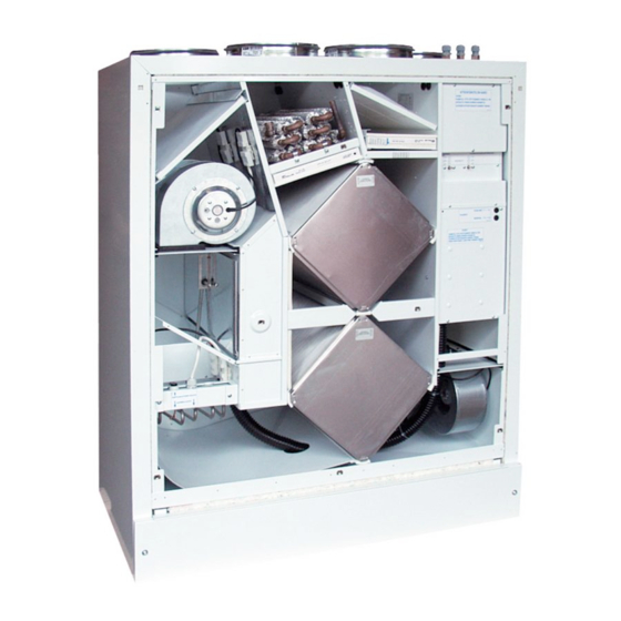
VALLOX 252 M
WATER OPERATED POST-
HEATING UNIT (OPTIONAL)
ELECTRICAL
POST-HEATING UNIT
(OPTIONAL)
ELECTRICAL PREHEATER
(OPTIONAL)
PRESSURE DIFFERENCE
SWITCH
(OPTIONAL)
Power supply
Protection class
Fans
Supply air
2x230 W 1 A
Discharge air
2x230 W 1 A
Heat recovery
Heat recovery bypass
Preheater
Electric post-heating unit
Water post-heating unit
Filters
Supply air
Discharge air
Weight/basic unit
Ventilation adjustment
options
Options
230 V, 50 Hz, (230 V / 400 V)
13,9 A (+preheater 10,9 A)
IP 34
3
210 dm
/s 100 Pa
3
230 dm
/s 100 Pa
2 heat recovery cells,
η
>70 %
Manual or remote monitoring control
2,5 kW 11 A
2,5 kW 11 A
Approx. 5kW
EU 3
EU 7
EU 3
EU 5
210 kg
– manual control (manual control unit)
– remote monitoring control
– sound attenuator
– preheater
– electric post-heating unit
– water post-heating
– pressure difference switch unit
VALLOX-product code:
VALLOX 252 M
HVAC code:
VALLOX 252 M
SOUND ATTENUATOR
(OPTIONAL)
IVALLOX 252
MANUAL
CONTROL CENTER
REMOTE MONITORING
CONNECTION
3158500 L
3158510 R
7911076 L
7911077 R
Advertisement

Related Manuals for Vallox 252 M


Summary of Contents for Vallox 252 M
- Page 1 VALLOX-product code: 3158500 L VALLOX 252 M 3158510 R HVAC code: 7911076 L VALLOX 252 M 7911077 R SOUND ATTENUATOR (OPTIONAL) IVALLOX 252 VALLOX 252 M WATER OPERATED POST- HEATING UNIT (OPTIONAL) ELECTRICAL POST-HEATING UNIT (OPTIONAL) ELECTRICAL PREHEATER (OPTIONAL) PRESSURE DIFFERENCE...
-
Page 2: Optional Equipment
-5°C. attenuator unit VALLOX 252 M can be operated with the manual cont- Installed above the unit rol unit contained in the delivery. With the manual control unit, you can select the min. or max. ventilation power, and stop the unit. - Page 3 Volume flow rate Fan curves: P = discharge air fan, T = supply air fan VALLOX 252 M VALLOX 252 M with Sound Attenuator with Sound Attenuator Measuring Points FAN CAPACITY Supply air Discharge air Recommended operating range Model L Measuring points after the outlet collar.
- Page 4 VALLOX 252 M SOUND VALUES • Sound power levels in the ducts measured in accordance Sound power level from VALLOX to supply Sound power level from VALLOX to with the standard ISO/DIS 5135:1995. air ducts by octave band L w , dB...
- Page 5 VALLOX 252 M WATER RADIATOR PERFORMANCE Pressure Loss in the Water Radiator The recommended area of operation is ruled. Determined for 100% water. Radiator + valve (KVS 1.0) Radiator Water flow Water Radiator Output Temperature of water entering the radiator (tv) 70 ˚C Temperature of water entering the radiator (tv) 55 ˚C...
- Page 6 VALLOX 252 M CONTROL DIAGRAM VALLOX 252 M - MANUAL CONTROL...
- Page 7 VALLOX 252 M DESCRIPTION OF OPERATION VALLOX 252 M - MANUAL CONTROL UNIT Control of Operation Heat Recovery Defrosting The TS5 temperature thermostat directs the operation of the preheater (LP1) The ventilation unit can be stopped by the fan speed switch on the ma- on the basis of the measurement data supplied by the temperature sensor, nual control unit.
- Page 8 VALLOX 252 M CONTROL DIAGRAM VALLOX 252 M VKL - MANUAL CONTROL UNIT...
- Page 9 Supply Air Temperature The threshold temperature for defrosting (-2...+6 ˚C) and the difference A regulating valve (not included in the VALLOX 252 M delivery) directs area (2 ˚C) can be set on the thermostat. the operation of the LP2 post-heating unit on the basis of the measurement data given by the thermostat sensor in the supply air duct.
- Page 10 VALLOX 252 M CONTROL DIAGRAM VALLOX 252 M REMOTE MONITORING CONTROL...
- Page 11 VALLOX 252 M DESCRIPTION OF OPERATION DIAGRAM VALLOX 252 M REMOTE MONITORING CONTROL Heat Recovery Defrosting Control of Operation The TS5 temperature thermostat directs the operation of the preheater If needed, the ventilation unit can be stopped by controlling the contac- (LP1) on the basis of the measurement data supplied by the temperature tors in the unit (Min., 1/2, Max.) or by controlling power supply via the...
- Page 12 VALLOX 252 M CONTROL DIAGRAM VALLOX 252 M VKL REMOTE MONITORING CONTROL...
- Page 13 VALLOX 252 M DESCRIPTION OF OPERATION VALLOX 252 M VKL REMOTE MONITORING CONTROL UNIT Heat Recovery Defrosting Control of Operation The TS5 temperature thermostat directs the operation of the preheater If needed, the ventilation unit can be stopped by controlling the contac- (LP1) on the basis of the measurement data supplied by the temperature tors in the unit (Min., 1/2, Max.) or by controlling power supply via the...
-
Page 14: Mounting Instructions
1/2" equipped with a separate sensor. The valve is installed in the return water Example of Pipe Connections pipe, and the sensor in the supply duct outside VALLOX. Because of the risk of VALLOX 252 M VKL freezing in the heating unit, it is recommended to use a pipe connection as shown in the figure (A). - Page 15 SOUND ATTENUATOR General • The sound attenuator is a duct silencer that should be mounted on top of VALLOX 252 M. The attenuator includes a cover that can be opened, enabling the cleaning of the attenuator without detaching the ducts.
- Page 16 NOTE! VALLOX 252 model L or R. (See the figure.) • Lift the sound attenuator unit on top of VALLOX 252. Make sure that the cable sleeves go through. (See the figure, item D.) •...
- Page 17 VALLOX 252 M MOUNTING INSTRUCTIONS VALLOXs Electrical Connections ONLY AN AUTHORIZED PERSON MAY PERFORM ELECTRICAL CONNECTIONS! • The unit is connected permanently to the electrical power network. The connection box is located inside the unit, next to the extract air duct outlet.
- Page 18 VALLOX 252 M INTERNAL WIRING DIAGRAM VALLOX 252 M TF = Supply air fan 2x230W K4 = Contactor, disconnection of the heating units for heat recovery bypass PF = Discharge air fan 2x230W = Service switch (door switch) C = Capacitor 6mF...
- Page 19 VALLOX 252 M EXTERNAL ELECTRICAL CONNECTIONS VALLOX 252 M - MANUAL CONTROL POS. 2 STATUS POS. 1 MAX. MIN. STATUS 24VAC MAX. MIN. N / 24VAC...
- Page 20 VALLOX 252 M EXTERNAL ELECTRICAL CONNECTIONS VALLOX 252 REMOTER MONITORING CONTROL POS. 2 STATUS POS. 1 MAX. MIN. STATUS 24VAC MAX. MIN. N / 24VAC Vallox Oy FIN-32200 Loimaa Finland Tel: +358 2 7636 300 Fax: +358 2 7631 539 Internet: www.vallox.com...
Need help?
Do you have a question about the 252 M and is the answer not in the manual?
Questions and answers