Table of Contents
Advertisement
Quick Links
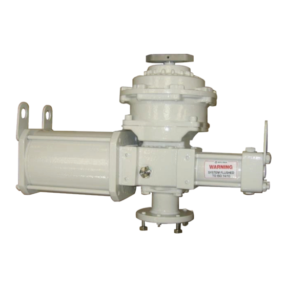
Biffi RPHS
Spring-Return Hydraulic Actuator
Copyright © Biffi. The information in this document is subject to change without notice. Updated data sheets can be obtained from our website www.biffi.it or from your nearest Biffi Center:
Biffi Italia s.r.l. - Strada Biffi 165, 29017 Fiorenzuola d'Arda (PC) – Italy PH: +39 0523 944 411 – biffi_italia@biffi.it
Installation, Operation and Maintenance Manual
MAN 605 Rev. 4
February 2021
Advertisement
Table of Contents

Related Manuals for BIFFI RPHD-10


Summary of Contents for BIFFI RPHD-10
- Page 1 Spring-Return Hydraulic Actuator Copyright © Biffi. The information in this document is subject to change without notice. Updated data sheets can be obtained from our website www.biffi.it or from your nearest Biffi Center: Biffi Italia s.r.l. - Strada Biffi 165, 29017 Fiorenzuola d'Arda (PC) – Italy PH: +39 0523 944 411 – biffi_italia@biffi.it...
- Page 2 Revision Details Installation, Operation and Maintenance Manual February 2021 MAN 605 Rev. 4 Revision Details Rev. Date Description Prepared Checked Approved February 2021 Migration to new template 18/04/06 Updated applicable regulation (chapter 1.1.1) Ermanni Orefici Vigliano 09/09/14 General Update Ermanni Cristalli Vigliano 11/12/09...
-
Page 3: Table Of Contents
Installation, Operation and Maintenance Manual Table of Contents MAN 605 Rev. 4 February 2021 Table of Contents Section 1: General Warnings Generalities ....................1 Identification Plate ..................2 Introducing the Actuator ................3 Data Sheet ....................4 Section 2: Installation Checks Upon Actuator Receipt .............. - Page 4 Notes Installation, Operation and Maintenance Manual February 2021 MAN 605 Rev. 4 This page is intentionally left blank...
-
Page 5: Section 1: General Warnings
Biffi Italia s.r.l. pays the highest attention to collecting and verifying the documentation contained in this user manual. However Biffi Italia s.r.l. is not liable for any mistakes contained in this manual, for damage or accidents due to the use of the latter. -
Page 6: Identification Plate
1.1.2 Terms and Conditions Biffi Italia s.r.l. guarantees that all the items produced are free of defects in workmanship and manufacturing materials and meet relevant current specifications, provided they are installed, used and serviced according to the instructions contained in the present manual. -
Page 7: Introducing The Actuator
Installation, Operation and Maintenance Manual Section 1: General Warnings MAN 605 Rev. 4 February 2021 Introducing the Actuator RPHS are hydraulic high-pressure spring-return actuators, suitable for any quarter turn application such as ball, plug, butterfly valves or dampers, in both ON-OFF and MODULATING heavy-duty service. -
Page 8: Data Sheet
Section 1: General Warnings Installation, Operation and Maintenance Manual February 2021 MAN 605 Rev. 4 Data Sheet Supply fluid Hydraulic oil or fire-resistant fluid Operating temperature Standard: from –30 °C to +100 °C Optional: from –60 °C to +140 °C Design pressure Design pressure of the cylinder 220 barg Supply pressure... -
Page 9: Section 2: Installation
Installation, Operation and Maintenance Manual Section 2: Installation MAN 605 Rev. 4 February 2021 Section 2: Installation Checks Upon Actuator Receipt • Check that the model, the serial number of the actuator and the technical data reported on the identification plate correspond with those of order confirmation (Section 1.2). - Page 10 Section 2: Installation Installation, Operation and Maintenance Manual February 2021 MAN 605 Rev. 4 Figure 3 Lifting and storage method 1-2= lifting points (obligatory) WARNING 1 = point of support (lifting points) 2= don’t lay the actuator on tie-rods Don’t lay the actuator on accessories (manual hand-pump, manual jack-screw, hydraulic control group etc.).
-
Page 11: Storage
NOTICE To fix the actuator to the valve flange must be used the stud bolts and nuts supplied by Biffi! In case the actuator is supplied without stud bolts and nuts the following materials must be used as a minimum: •... - Page 12 - All dimensions are in mm - Actuator shown in closed position Table 1. Actuator Model ØC ØH ± 0,2 ± 0,2 ØE ØF Ø ØM -0,1 -0,5 -0,2 RPHD-10 49.5 49.5 RPHS-10 RPHD-20 72.1 72.1 RPHS-20 RPHD-40 88.4 88.4 RPHS-40 RPHD-80 RPHS-80 Installation...
- Page 13 Installation, Operation and Maintenance Manual Section 2: Installation MAN 605 Rev. 4 February 2021 2.4.2 Assembly Procedure NOTICE Failure to comply with the following procedures may impair product warranty. WARNING Installation, commissioning and maintenance and repair works should be carried out by qualified staff.
-
Page 14: Hydraulic Connections
Section 2: Installation Installation, Operation and Maintenance Manual February 2021 MAN 605 Rev. 4 Hydraulic Connections NOTICE Check that the values of hydraulic supply available in the system are compatible with those reported on the identification plate of the actuator. The connections should be made by qualified staff. -
Page 15: Electrical Connections (If Any)
Installation, commissioning and maintenance and repair works should be made by qualified staff. Any calibration relative to functional aspects of the actuator are preset at the factory. Before any modifications please read Biffi Italia s.r.l. Upon actuator commissioning please carry out the following checks: •... -
Page 16: Section 3: Operation And Use
Section 3: Operation and Use Installation, Operation and Maintenance Manual February 2021 MAN 605 Rev. 4 Section 3: Operation and Use Operation Description The oil supply pressurizes the hydraulic cylinder chamber relevant to the operation to carry out (opening or closing) (see following pages). This pressure starts the linear motion of the piston and the consequent rotation motion of the rack and pinion mechanism, to which the valve stem is coupled, in one direction. - Page 17 Installation, Operation and Maintenance Manual Section 3: Operation and Use MAN 605 Rev. 4 February 2021 Local control suitable also for remote oil supply for spring-return actuators. Figure 6 1. Rack and pinion mechanism 2. Hydraulic cylinder 3. Spring cartridge 4.
-
Page 18: Residual Risks
Section 3: Operation and Use Installation, Operation and Maintenance Manual February 2021 MAN 605 Rev. 4 Residual Risks WARNING The actuator has parts under pressure. Use the due caution. Use the due caution. Use individual protections provided for by the laws and provisions in force. Operations The operations are carried out sending the proper signal through the control system in compliance with Customer specifications. - Page 19 Installation, Operation and Maintenance Manual Section 3: Operation and Use MAN 605 Rev. 4 February 2021 Figure 7 Table 3. Hydraulic Cylinder Diameter Wrench C1 (mm) Wrench C2 (mm) From 28 to 40 From 45 to 60 From 70 to 175 From 200 to 235 Travel stop screw screwed on the end flange of spring container For the adjustment of the travel stop screw proceed as follows:...
-
Page 20: Calibration Of Microswitches (If Foreseen)
Section 3: Operation and Use Installation, Operation and Maintenance Manual February 2021 MAN 605 Rev. 4 To operate the adjustments refer to following table: Table 4. Spring Container Size Wrench C1 (mm) Wrench C2 (mm) Figure 8 Calibration Of Micro-switches (If Foreseen) NOTICE Operate only the micro-switches corresponding to the direction of operation being carried out, as clearly reported on the micro-switch. - Page 21 Installation, Operation and Maintenance Manual Section 3: Operation and Use MAN 605 Rev. 4 February 2021 Figure 9 Micro-switches box Figure 10 Cam adjustment Operation and Use...
- Page 22 Section 3: Operation and Use Installation, Operation and Maintenance Manual February 2021 MAN 605 Rev. 4 If the index (Figure 11), does not signal the proper position of the valve but is turned by 90°: • Remove the roll pin placed on the position indicator (index). •...
-
Page 23: Calibration Of The Operation Time
February 2021 Calibration of the Operation Time The calibration of the operation time is made by Biffi Italia s.r.l. according to customer requirements and to technical data-sheet included in technical documentation. If necessary it’s possible to modify or reset the operating time through two flow regulation valves placed on inlets of hydraulic cylinder (Figure 12). -
Page 24: Section 4: Operational Tests And Inspections
Section 4: Operational Tests and Inspections Installation, Operation and Maintenance Manual February 2021 MAN 605 Rev. 4 Section 4: Operational Tests and Inspections NOTICE To ensure the guaranteed SIL grade, according to IEC 61508, the functionality of actuator must be checked with regular intervals of time, as described in the Safety Manual. Operational Tests and Inspections... -
Page 25: Section 5: Maintenance
Installation, Operation and Maintenance Manual Section 5: Maintenance MAN 605 Rev. 4 February 2021 Section 5: Maintenance NOTICE Before executing any maintenance operation, it is necessary to close the hydraulic supply line and discharge pressure from the cylinder of the actuator and from the control unit (if foreseen). - Page 26 NAS 8 minimum. For actuators with control system the cleanliness level is that required by singles components, in any case Biffi Italia s.r.l. respect the customer requirements to scope of supply, for applicable cleanliness level, refer to document: technical data sheet for actuators.
-
Page 27: Extraordinary Maintenance
Installation, Operation and Maintenance Manual Section 5: Maintenance MAN 605 Rev. 4 February 2021 Extraordinary Maintenance If there are leaks in the hydraulic cylinder or a malfunction in the mechanical components, or in case of scheduled preventive maintenance, the actuator must be disassembled and seals must be replaced with reference to the follow general sectional drawing and adopting the following procedures: 5.2.1... - Page 28 Section 5: Maintenance Installation, Operation and Maintenance Manual February 2021 MAN 605 Rev. 4 Seals replacement: If the O-ring/seals must be replaced, remove the existing one from its groove, clean the groove carefully and lubricate it with protective oil film (SHELL Omala S4 WE 320 or equivalent).
- Page 29 Installation, Operation and Maintenance Manual Section 5: Maintenance MAN 605 Rev. 4 February 2021 Figure 13 RPHS spring-return hydraulic actuator 23 22 Table 7. Item Description Item Description End spring flange Plug Spring guide flange O-ring Spring Tie rod Spring cartridge tube O-ring Retainer ring Plug...
-
Page 30: Lubrication Of Mechanism
Check that the actuator components are in good conditions and clean. Substitute the gaskets and the O-Rings if worn or damaged. Assemble all the components, taking care not to damage the seals. The following grease is used by Biffi for standard working temperature and suggested for relubrication: Table 8. -
Page 31: Dismantling And Demolition
Installation, Operation and Maintenance Manual Section 5: Maintenance MAN 605 Rev. 4 February 2021 Dismantling and Demolition WARNING Before starting the disassembly a large area should be created around the actuator so to allow any kind of movement without problems of further risks created by worksite. Before disassembling the actuator it is necessary to close the pneumatic feed line and discharge pressure from the cylinder of the actuator, from the control unit and from the accumulator tank, if present. -
Page 32: Section 6: Troubleshooting
Wrong position of the distributor of the Clogged filter Restore correct position manual hydraulic group Failure of the control group Call Biffi Italia s.r.l. Customer Service Low supply pressure Restore (Section 1.4) Low supply pressure Restore (Section 1.4) Actuator too slow Wrong calibration of flow regulator valves Restore (Section 3.6) -
Page 33: Section 7: Layouts
Section 7: Layouts Spare Parts Order For spare parts order to the relevant Biffi office please make reference to Biffi order confirmation concerning all the supply, and serial number of the actuator (Section 1.2) for any specific spare part for a specific actuator model. -
Page 34: Parts List Ror Maintenance And Replacing Procedure
Section 7: Layouts Installation, Operation and Maintenance Manual February 2021 MAN 605 Rev. 4 Parts List ror Maintenance and Replacing Procedure Figure 14 RPHS Spring to Close Hydraulic Actuator 48-49 Layouts... - Page 35 Installation, Operation and Maintenance Manual Section 7: Layouts MAN 605 Rev. 4 February 2021 Table 10. Item Description Material Housing Nodular cast iron Rack Alloy steel Pinion Alloy steel Cover Carbon steel Screw Alloy steel Bushing Fe + Bz + Teflon Cylinder tube Nickel-plated carbon steel Piston...
-
Page 36: Section 8: Date Report For Maintenance Operations
Section 8: Date Report for Maintenance Operations Installation, Operation and Maintenance Manual February 2021 MAN 605 Rev. 4 Section 8: Date Report for Maintenance Operations Last maintenance operation date: (in factory, on delivery): ……… exec. by: ………… ……… exec. by: ………… ………... - Page 37 Installation, Operation and Maintenance Manual Notes MAN 605 Rev. 4 February 2021 This page is intentionally left blank...
- Page 38 VCIOM-03748-EN ©2021 Biffi. All rights reserved. Biffi Italia s.r.l. Strada Biffi 165 The contents of this publication are presented for information purposes only, 29017 Fiorenzuola d’Arda (PC) and while every effort has been made to ensure their accuracy, they are not...
Need help?
Do you have a question about the RPHD-10 and is the answer not in the manual?
Questions and answers