Westermo ODW-730-F1 User Manual
Fibre optic modem industrial converter rs-485 to fibre optic link point to point applications
Hide thumbs
Also See for ODW-730-F1:
- User manual (21 pages) ,
- User manual (21 pages) ,
- User manual (54 pages)

Subscribe to Our Youtube Channel
Related Manuals for Westermo ODW-730-F1


Summary of Contents for Westermo ODW-730-F1
- Page 1 User Guide 6651-2241 ODW-730-F1 Fibre Optic Modem Industrial Converter RS-485 to Fibre Optic Link Point to Point applications www.westermo.com...
-
Page 2: Legal Information
Under no circumstances shall Westermo be responsible for any loss of data or income or any special, incidental, and consequential or indirect damages howsoever caused. -
Page 3: Before Installation
Do not use or store the unit in dusty, dirty areas. Connectors as well as other mechanical parts may be damaged. If the unit is not working properly, contact the place of purchase, nearest Westermo distributor office, or Westermo Tech support. -
Page 4: Maintenance
Note. Fibre Optic Handling Fibre optic equipment requires careful handling as the fibre components are very sensitive to dust and dirt. If the fibre is disconnected from the modem, the protective plug on the transmitter/receiver must be replaced. The protective plug must be kept on during transportation. -
Page 5: Agency Approvals And Standards Compliance
Agency approvals and standards compliance Type Approval / Compliance EN 61000-6-1, Immunity residential environments EN 61000-6-2, Immunity industrial environments EN 61000-6-3, Emission residential environments EN 61000-6-4, Emission industrial environments EN 50121-4, Railway signalling and telecommunications apparatus IEC 62236-4, Railway signalling and telecommunications apparatus DNV Standard for Certification no. -
Page 6: Declaration Of Conformity
Declaration of Conformity Westermo Teleindustri AB Declaration of Conformity The manufacturer Westermo Teleindustri AB SE-640 40 Stora Sundby, Sweden Herewith declares that the product(s) Type of product Model Art no Industrial fiberoptic repeaters/mediaconverters ODW-700 series 3651-07xx is in conformity with the following EU directive(s). -
Page 7: Type Tests And Environmental Conditions
Type tests and environmental conditions Electromagnetic Compatibility Phenomena Test Description Level EN 61000-4-2 Enclosure contact ± 6 kV Enclosure air ± 8 kV RF field AM modulated IEC 61000-4-3 Enclosure 10 V/m 80% AM (1 kHz), 80 – 800 MHz 20 V/m 80% AM (1 kHz), 800 –... -
Page 8: Functional Description
Functional description LED’s Switches POWER Internal Electronics ODW-730 RS -485 STATUS T/R+ CH 1 OVP Over Voltage Protection Fibre transceiver OCP Over Current Protection Converter serial interface – optical fibre ODW-730 is a fibre optic modem that converts between electrical RS-485 and a fibre optical link. -
Page 9: Interface Specifications
Interface specifications Power Rated voltage 12 to 48 VDC and 24 VAC Operating voltage 10 to 60 VDC and 20 to 30 VAC Rated current 300 mA @ 12 V 150 mA @ 24 V 75 mA @ 48 V Rated frequency DC and 48 to 62 Hz Inrush current I²t... - Page 10 RS-422/485 Electrical specification EIA RS-485, 2-wire or 4-wire twisted pair Data rate 300 bit/s – 1.5 Mbit/s Data format 9 – 12 bits Protocol Start-bit followed by 8-11 bits Retiming Turning time One t (2-wire RS-485) = 1 / Baud rate (Baud rate in bit/s) Transmission range <...
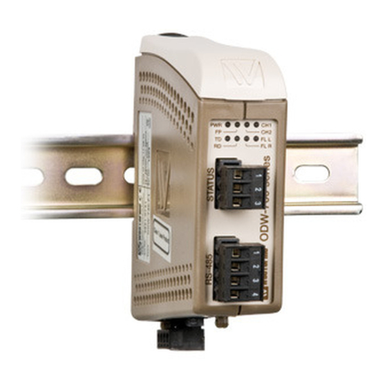
- Page 11 Location of Interface ports, LED’s and DIP-switches ODW-730-F1 LED Indicators DIP-switches accessible under lid Status screw terminal Position Description Product marking Contact with C when fibre optical links are in operation Common Open (no contact with C) when fibre optical links are...
-
Page 12: Led Indicators
LED indicators Status Description Power is on. Power Power is off. Not used CH 2 Not used CH 1 Fiber link to other unit has been established at CH 1. Channel 1 link status Flashing Optical power detected but link to other unit has not been established at CH 1. -
Page 13: Dip Switch Settings
DIP-switch settings Before DIP-switch settings: Prevent damage to internal electronics from electrostatic discharges (ESD) by discharging your body to a grounding point (e.g. use of wrist strap) Note: Disconnect power before DIP-switch settings. S1 DIP-switch, asynchronous mode speed selection 300 bit/s 57.6 kbit/s 1.0 Mbit/s 1 2 3 4 5 6 7 8... -
Page 14: Factory Default
S1 DIP-switch, synchronous mode time frame selection 1.6 ms 13 µs 2 µs 1 2 3 4 5 6 7 8 1 2 3 4 5 6 7 8 1 2 3 4 5 6 7 8 416 µs 8.6 µs 1 µs 1 2 3 4 5 6 7 8 1 2 3 4 5 6 7 8... - Page 15 … Make sure that DIP-switches S1:8 and S2:2 – S2:8 are set to factory default positions. (I.e. S1:8 OFF, S2:2 OFF, S2:3 ON and S":4 – S2:8 OFF). … Configure both ODW-730-F1 units for the correct speed and data format using DIP- switches S1:1 – S1:7.
- Page 16 RS-485 termination at system level The system should be installed in according to the RS-485 specification. A system should always form a bus structure where the termination is at the end points of the bus. See diagrams for details of how this is done with RS-485 2-wire and 4-wire. R–...
-
Page 17: Power Terminal
About the interfaces Power terminal The power terminal has two independent inputs, +VA and +VB, allowing redundancy should either fail. The ODW-730 power supply is galvanically isolated from all other internal electronics. Optical fibre interfaces ODW-730 uses Small From Factor Pluggable (SFP) transceivers that are in compliance with the Multi-Sourcing Agreement (MSA). - Page 18 Mounting This unit should be mounted on 35 mm DIN-rail, which is horizontally mounted inside an apparatus cabinet, or similar. Snap on mounting, see figure. Cooling 10 mm * (0.4 inches) This unit uses convection cooling. To avoid obstructing the 25 mm airflow around the unit, use the following spacing rules.
- Page 19 6651-2241...
-
Page 20: Sales Units
France Singapore Other Offices infos@westermo.fr sales@westermo.com.sg www.westermo.fr www.westermo.com Germany Sweden info@westermo.de info.sverige@westermo.se www.westermo.de www.westermo.se For complete contact information, please visit our website at www.westermo.com/contact or scan the QR code REV. J 6651-2241 2017-02 Westermo Teleindustri AB, Sweden...
Need help?
Do you have a question about the ODW-730-F1 and is the answer not in the manual?
Questions and answers