Table of Contents
Advertisement
Quick Links
REV. 1.5
th
Jan., 29
2009
HD2303.0
Our instruments' quality level is the results of the product continuous development. This
can bring about differences between the information written in this manual and the
instrument that you have purchased. We cannot entirely exclude errors in the manual, for
which we apologize.
The data, figures and descriptions contained in this manual cannot be legally asserted. We
reserve the right to make changes and corrections without prior notice.
Advertisement
Table of Contents

Subscribe to Our Youtube Channel
Related Manuals for Delta OHM HD2303.0


Summary of Contents for Delta OHM HD2303.0
- Page 1 REV. 1.5 Jan., 29 2009 HD2303.0 Our instruments' quality level is the results of the product continuous development. This can bring about differences between the information written in this manual and the instrument that you have purchased. We cannot entirely exclude errors in the manual, for which we apologize.
- Page 2 Anemometer HD2303.0...
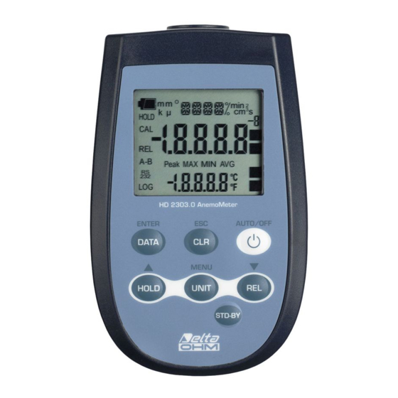
- Page 3 HD2303.0 1. Input for probes, 8-pole DIN45326 connector. 2. Battery symbol: displays the battery charge level. 3. Function indicators. 4. Secondary display line. 5. DATA/ENTER key: during normal operation displays the maximum (MAX), the minimum (MIN) and the average (AVG) of current measurements; in the menu, confirms the current selection.
-
Page 4: Table Of Contents
TABLE OF CONTENTS 1. GENERAL CHARACTERISTICS..........................5 2. DESCRIPTION OF THE FUNCTIONS ........................6 3. THE PROGRAMMING MENU ..........................9 4. PROBES AND MEASUREMENTS.......................... 10 4.1 W ........................... 10 IND SPEED MEASUREMENT 4.1.1 Flow rate measurement ..........................11 4.2 H SICRAM .............. -
Page 5: General Characteristics
1. GENERAL CHARACTERISTICS The Anemometer Model HD2303.0 is a portable instrument that allows to perform measurements in the fields of air conditioning, heating and ventilation. It is fitted with a large LCD display for excellent visualization of the measured data. The Anemometer Model HD2303.0:... -
Page 6: Description Of The Functions
2. DESCRIPTION OF THE FUNCTIONS The keyboard of the Anemometer Model HD2303.0 is composed of double-function keys. The function on the key is the "main function", while the one above the key is the "secondary function". When the instrument is in standard measurement mode, the main function is active. - Page 7 CLR/ESC key The "CLR" key has two functions: • CLEAR (CLR): allows to reset the maximum (MAX), minimum (MIN) and average (AVG) value of the captured measurements; • ESC: once the MENU has been opened with the DATA+UNIT keys, the CLR key will allow to cancel the parameters set using the arrows.
- Page 8 UNIT/MENU key The UNIT key is used for the following functions: • UNIT: by pressing this key the unit of measurement of the main input quantity is selected: the unit of measurement will appear in the upper part of the display; the measured value will be displayed in the central line.
-
Page 9: The Programming Menu
3. THE PROGRAMMING MENU To access to the menu press simultaneously the following keys: The items to be set are listed in this order: 1. SECT m - SECT inch : this parameter defines a duct's section area for flow rate calculation. -
Page 10: Probes And Measurements
4. PROBES AND MEASUREMENTS The Anemometer works with hot-wire, vane and temperature probes fitted with the SICRAM module. It works also with temperature probes with 4 wire Pt100 or 2 wire Pt1000 sensor. Some probes are fitted with SICRAM module that acts as an interface between the sensor on the probe and the instrument. -
Page 11: Flow Rate Measurement
4.1.1 Flow rate measurement The flow rate measurement requires knowledge of the duct or vent area orthogonal to the flow: the menu items indicated by "SECT m2" and "SECT INC2" define the section area m or inch To set the area value: press simultaneously DATA and UNIT to open the menu;... -
Page 12: Hot - Wire Wind Speed Measurement Probes With Sicram Module
4.2 H SICRAM WIRE WIND SPEED MEASUREMENT PROBES WITH MODULE The hot-wire wind speed measurement probes, fitted with SICRAM module, are the models: • AP471 S1 • AP471 S2 • AP471 S3 • AP471 S4 • AP471 S5. The AP471 S1 and AP471 S3 probes measure incident air flows up to 40m/s. The AP471 S2, AP471 S4 and AP471 S5 probes are fitted with an omnidirectional sensor allowing measurement of speeds up to 5m/s in any direction of the air flow incident on the probe. - Page 13 The AP471 S1, S2 and S3 probes are fitted with a cylindrical protection screen that can slide longitudinally over a groove. The screen has two end-of-travel positions that block it in measurement condition (completely low) or rest condition (completely high). To reduce the space occupied when not used, the AP471 S4 and AP471 S5 are supplied with a protection cylinder that can be screwed on the probe's head.
-
Page 14: Operation
4.2.1 Operation 1. Extend the telescopic rod to the necessary length paying attention to the cable so that it can slide freely and without strain; 2. Uncover the sensor; 3. Introduce the probe in the air flow being measured, maintaining the arrow at the top of the probe parallel to the flow, as indicated in the figures. -
Page 15: Warnings, Care And Maintenance Of The Probes
4.2.2 Warnings, care and maintenance of the probes The speed sensor of the AP471 Sx probes is heated and, in the presence of gas vapours, could trigger a fire or explosion. Do not use the probe in the presence of inflammable gases. - Page 16 ∅=120 AP471 S4 AP471 S5...
-
Page 17: Vane Wind Speed Measurement Probes With Sicram Module
4.3 V SICRAM ANE WIND SPEED MEASUREMENT PROBES WITH MODULE The AP472 S1, AP472 S2 and AP472 S4 vane probes measure the incident wind speed and flow rate. The AP472 S1, AP472 S4LT and AP472 S4HT probes measure also the temperature using a thermocouple of type K. -
Page 18: Care And Maintenance Of The Probes
NOTE: the probe should be maintained orthogonal to the flow and not tilted in relation to it: The probe is correctly positioned in relation to the air-flow when the value measured is the maximum possible. 3. Proceed with measurement following the instructions provided in the introductory paragraphs of this chapter. -
Page 19: Dimensions
4.3.4 Dimensions ø100 ø60 ø16 AP472 S1 AP472 S2 AP472 S4... - Page 20 Further to the telescopic extension shaft with the directional head, the probes AP472S1 – AP472 S2 can be used with the stiff extension shaft diam.16mm. In order to screw the handle off (3) hold the probe tight on point (1). Screw the shaft top AP471S1.23.6 on the screw (2). Other extension shafts AP471S1.23.6 can be added.
-
Page 21: Direct Input Into Pt100 And Pt1000 Temperature Probes
All probes produced by Delta Ohm are provided with a connector. The HD2303.0 instrument also work with direct 4 wire Pt100, and 2 wire Pt1000 probes manufactured by other producers: for the instrument connection is prescribed the TP47 connector to which the probe's wires should be welded. -
Page 22: Direct Connection Of 4 Wire Pt100 Sensors
5. open the two module shells: the printed circuit to which the probe must be connected is housed inside. On the left there are the 1…4 points on which the sensor wires must be welded. The JP1…JP4 jumpers are in the center of the board. These must be closed with a tin bead for some type of sensors: Not Used Ni1000... -
Page 23: Warnings
5. WARNINGS 1. Temperature probes are not insulated from their external casing; be very careful not to come into contact with live parts (above 48V). This could be extremely dangerous for the instrument as well as for the operator, who could be electrocuted. 2. -
Page 24: Instrument Signals And Faults
6. INSTRUMENT SIGNALS AND FAULTS The following table lists all error indications and information displayed by the instrument and supplied to the user in different operating situations: Display indications Explanation This appears in the display central line when a temperature only probe is connected. - - - In the lower line the temperature is shown correctly. -
Page 25: Low Battery Warning And Battery Replacement
8. LOW BATTERY WARNING AND BATTERY REPLACEMENT The battery symbol on the display constantly shows the battery charge status. To the extent that batteries have discharged, the symbol "empties". When the charge decreases still further it starts blinking. In this case, batteries should be replaced as soon as possible. If you continue to use it, the instrument can no longer ensure correct measurement. -
Page 26: Notes About Working And Operative Safety
9. NOTES ABOUT WORKING AND OPERATIVE SAFETY Authorized use The technical specifications as given in chapter TECHNICAL CHARACTERISTICS must be observed. Only the operation and running of the measuring instrument according to the instructions given in this operating manual is authorized. Any other use is considered unauthorized. General safety instructions This measuring system is constructed and tested in compliance with the EN 61010-1 safety regulations for electronic measuring instruments. -
Page 27: Technical Characteristics
10. TECHNICAL CHARACTERISTICS 10.1 T ECHNICAL INFORMATION ON THE NEMOMETER Instrument Dimensions (Length x Width x Height) 140 x 88 x 38 mm Weight 160 g (complete with batteries) Material Display 2x4½ digits plus symbols Visible area: 52 x 42 mm Operating conditions -5 ÷... -
Page 28: On Line Instrument Probes And Modules Technical Data
10.2 ON LINE INSTRUMENT PROBES AND MODULES TECHNICAL DATA 10.2.1 Wind speed measurement probes Hot-wire probes: AP471 S1 - AP471 S2 - AP471 S3 - AP471 S4 - AP471 S5 AP471 S4 AP471 S1 - AP471 S3 AP471 S2 AP471 S5 Wind speed, calculated flow rate, air temperature Type of measurements Type of sensor... - Page 29 Vane probes: AP472 S1… - AP472 S2 - AP472 S4… AP472 S4… AP472 S1 AP472 S2 …L …LT …H …HT Wind speed, Wind speed, Type of measurements calculated flow rate, calculated flow rate air temperature Diameter 100 mm 60 mm 16 mm Type of measurement Speed...
-
Page 30: Temperature Probes Pt100 Sensor Using Sicram Module
10.2.2 Temperature probes Pt100 sensor using SICRAM module Model Type Application range Accuracy ±0.25°C (-196°C…+350°C) TP472I Immersion -196°C…+500°C ±0.4°C (+350°C…+500°C) ±0.25°C (-50°C…+350°C) TP472I.0 Immersion -50°C…+400°C ±0.4°C (+350°C…+400°C) ±0.25°C (-50°C…+350°C) TP473P.0 Penetration -50°C…+400°C ±0.4°C (+350°C…+400°C) ±0.3°C (-50°C…+350°C) TP474C.0 Contact -50°C…+400°C ±0.4°C (+350°C…+400°C) TP475A.0 -50°C…+250°C ±0.3°C (-50°C…+250°C) -
Page 31: Order Codes
11. ORDER CODES HD2303.0 The kit is composed of the HD2303.0, 3 1.5V alkaline batteries, operating manual, and case. The probes must be ordered separately. 11.1 P SICRAM ROBES COMPLETE WITH MODULE WIND SPEED MEASUREMENT PROBES • HOT-WIRE PROBES AP471 S1 Hot-wire telescopic probe, measuring range: 0.05…40m/s. -
Page 32: Temperature Probes Without Sicram Module
TEMPERATURE MEASUREMENT PROBES TP472I Pt100 sensor immersion probe. Stem Ø 3 mm, length 300 mm. Cable length 2 metres. TP472I.0 Pt100 sensor immersion probe. Stem Ø 3 mm, length 230 mm. Cable length 2 metres. TP473P.0 Pt100 sensor penetration probe. Stem Ø 4 mm, length 150 mm. Cable length 2 metres. - Page 33 CERTIFICATO DI CONFORMITÀ DEL COSTRUTTORE MANUFACTURER’S CERTIFICATE OF CONFORMITY rilasciato da issued by DELTA OHM SRL STRUMENTI DI MISURA DATA 2009/01/29 DATE Si certifica che gli strumenti sotto riportati hanno superato positivamente tutti i test di produzione e sono conformi alle specifiche, valide alla data del test, riportate nella documentazione tecnica.
- Page 34 All DELTA OHM instruments have been subjected to strict tests and are guaranteed for 24 months from date of purchase. DELTA OHM will repair or replace free of charge any parts which it considers to be inefficient within the guarantee period. Complete replacement is excluded and no request of damages are recognized.
Need help?
Do you have a question about the HD2303.0 and is the answer not in the manual?
Questions and answers