Table of Contents
Advertisement
Quick Links
The quality level of our instruments is the result of a continuous improve of product. This
situation can cause possible differences comparing this manual with the instrument you
bought. We regret in advance for any possible mistake in this manual.
Data, drawings and descriptions included in this manual cannot be juridically in force. We
reserve us the right to modify and correct the manual without prior notice.
HD2102.1
HD2102.2
REV. 1.0
01 Oct. 2004
Advertisement
Table of Contents

Subscribe to Our Youtube Channel
Related Manuals for Delta OHM HD2102.1


Summary of Contents for Delta OHM HD2102.1
- Page 1 REV. 1.0 01 Oct. 2004 HD2102.1 HD2102.2 The quality level of our instruments is the result of a continuous improve of product. This situation can cause possible differences comparing this manual with the instrument you bought. We regret in advance for any possible mistake in this manual.
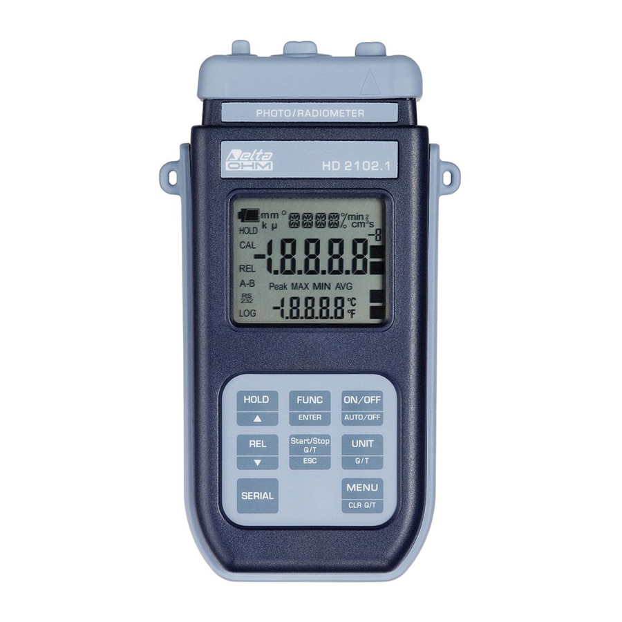
- Page 2 Photo-Radiometer HD2102.1...
- Page 3 HD2102.1 1. Input for probes, 8-pole DIN45326 connector. 2. External auxiliary power supply connector input. 3. Battery symbol: displays the battery charge level. 4. Function indicators. 5. Secondary display line. 6. HOLD key/ : freezes the measurement during normal operation; in the menu, increases the current value.
- Page 4 Photo-Radiometer HD2102.2...
- Page 5 HD2102.2 1. Input for probes, 8-pole DIN45326 connector. 2. External auxiliary power supply connector input. 3. Battery symbol: displays the battery charge level. 4. Function indicators. 5. Secondary display line. 6. HOLD key/ : freezes the measurement during normal operation; in the menu, increases the current value.
-
Page 6: Introduction
RS232C serial port and USB 2.0. The storing interval, printing, and baud rate can be configured using the menu. The HD2102.1 and HD2102.2 models are fitted with an RS232C serial port and can transfer the acquired measurements in real time to a PC or to a portable printer. -
Page 7: Keyboard And Menu Description
KEYBOARD AND MENU DESCRIPTION Foreword The instrument keyboard is composed of single-function keys, like the MENU key, and double- function keys such as the ON-OFF/Auto-OFF key. In the double-keys, the function in the upper part is the “main function”, while the one in the bottom part is the “secondary function”. - Page 8 FUNC/ENTER key During normal measurement this enables the display and logging of the maximum (MAX), minimum (MIN) and average (AVG) value of the measurements captured by the probe connected to the instrument, updating them with the acquisition of new samples. The acquisition frequency is once a second.
- Page 9 This setting changes the information displayed and the immediate print of data (SERIAL key). The data recorded using the LOG function (HD2102.2) and sent to the printer or PC through the serial port using the SERIAL function (HD2102.1 and HD2102.2), keep the chosen unit of measurement and display it.
- Page 10 before entering the menu. By pressing the UNIT key, it is possible to select the coefficient 3, 6 and 9 that multiplies the displayed value respectively by 10 , 10 , 10 2. TIME LIMT HOUR: indicates the number of hours for the integration time limit, after which the integral calculation is stopped.
- Page 11 13. BAUD_RATE: indicates the frequency used for the serial communication with the PC. Values from 1200 to 38400 baud. Use the arrows to modify this parameter and confirm using ENTER. The communication between instrument and PC (or serial port printer) only works if the instrument and PC baud rates are the same.
- Page 12 SERIAL key - only HD2102.1 SERIAL/EraseLOG key - only HD2102.2 In measurement mode, this function starts and stops the data transfer to the RS232C serial output. According to the settings entered in the Print and log interval menu item, a single sample can be printed if Print and log interval=0 or a continuous indefinite printing of the measured data can be set up if Print and log interval=1…3600.
-
Page 13: The Probes
THE PROBES The instrument works with probes of the LP471… series: these are photometric and radiometric probes that measure illuminance (LP471 PHOT), irradiance (LP471 RAD, LP471 UVA, LP471 UVB and LP471 UVC), PAR (LP471 PAR) and luminance (LP471 LUM 2). All the probes, save the LUM 2, are provided with a diffuser for cosine correction. - Page 14 Simultaneously press FUNC/ENTER and UNIT-Q(t). To start and stop the integral calculation press Start/Stop Q(t). To cancel the previous integration values and reset it, simultaneously press FUNC/ENTER and MENU/CLR-Q(t): if an integration is started without pressing the CLR- Q(t) key, the calculation will continue from the previous values. The integral calculation can be suspended at any moment pressing Start/Stop Q(t): in this status, to resume the integration, press the key again.
-
Page 15: Warnings And Operating Instructions
WARNINGS AND OPERATING INSTRUCTIONS 1. Do not bend the probe connectors or force them upward or downward. 2. Do not bend or force the contacts when inserting the probe connector into the instrument. 3. The sensors and filters should not exceed the temperature limits established with consequent irreparable degradation of their characteristics. - Page 16 The following table reports the indications provided by the instrument as they appear on the display, together with their description. Display indications Explanation >>>_LOG_DUMP_or_ERAS transfer or erase data BATT TOO LOW - CHNG NOW battery discharged - replace it immediately baud rate value BAUDRATE >>>...
-
Page 17: Low Battery Warning And Battery Replacement
LOW BATTERY WARNING AND BATTERY REPLACEMENT The battery symbol on the display constantly shows the battery charge status. To the extent that batteries have discharged, the symbol "empties". When the charge decreases still further it starts blinking… In this case, batteries should be replaced as soon as possible. If you continue to use it, the instrument can no longer ensure correct measurement. -
Page 18: Instrument Storage
ALFUNCTIONING UPON TURNING ON AFTER BATTERY REPLACEMENT After replacing the batteries, the instrument may not restart correctly; in this case, repeat the operation. After disconnecting the batteries, wait a few minutes in order to allow circuit condensers to discharge completely; then reinsert the batteries. ARNING ABOUT BATTERY USE •... -
Page 19: Serial Interface And Usb
The HD2102.1 and HD2102.2 instruments are fitted with an electrically isolated RS-232C serial interface; the HD2102.2 also has an USB 2.0 interface. The HD2102.1 is supplied with a serial connection cable with a Sub D 9-pole female connector on one end, and an 8-pole MiniDin on the other end. - Page 20 Command Response Description & Stop logging data & Enable REL function & Disable REL function & Auto-power-off function=ENABLE & Auto-power-off function=DISABLE Sample Interval= # Reading of LOG/PRINT interval set & 720 Battery level (Resolut. 0.01V) U= W/m2 Main unit of measurement Setting LOG/PRINT interval.
-
Page 21: Storing And Transferring Data To A Personal Computer
STORING AND TRANSFERRING DATA TO A PERSONAL COMPUTER The HD2102.1 and HD2102.2 instruments can be connected to a personal computer via an RS232C serial port, and exchange data and information through the DeltaLog9 software running in a Windows operating environment. The HD2102.2 can also use the USB connection. Both models can send in real time input measured values directly to a PC, through the PRINT function;... -
Page 22: The Print Function
PRINT FUNCTION The PRINT function sends the measurements taken in real time by the instrument inputs directly to a PC. Print data units of measurements are the same as those used on the display. The function is started by pressing SERIAL. The time interval between two consecutive prints can be set from 1 second to 1 hour (please see the Print and log interval menu item on page 9). -
Page 23: Connection To A Pc
CONNECTION TO A PC HD2102.1 connection to the PC with the cable code HD2110CSNM: sub D 9-pole female connector on one end – 8-pole MiniDin on the other end. HD2102.2 connection to the PC with the cable code HD2101/USB: USB type A connector on one end –... - Page 24 9. If the authorisation to search for an updated driver is requested, select NO and proceed. 10. On installation window, select the item “Install from a specific list or way”. 11. On next window select the options “Search the best driver available in these ways” and “Include the following way during the search”.
-
Page 25: Instrument Technical Characteristics
INSTRUMENT TECHNICAL CHARACTERISTICS Instrument Dimensions (Length x Width x Height) 185x90x40mm Weight 470g (complete with batteries) Materials ABS, rubber Display 2x4½ characters plus symbols Visible area: 52x42mm Operating conditions Operating temperature -5…50°C Storing temperature -25…65°C Working relative humidity 0…90%RH without condensation Protection degree IP67 Power... - Page 26 USB interface - model HD2102.2 Type 1.1 - 2.0 electrically isolated Connections Input module for the probes 8-pole male DIN45326 connector Serial interface and USB 8-pole MiniDin connector Mains adapter 2-pole connector (positive at centre) EMC standard regulations Security EN61000-4-2, EN61010-1 level 3 Electrostatic discharge EN61000-4-2 level 3 Electric fast transients...
-
Page 27: Technical Characteristics Of Photometric And Radiometric Probes Complete With Sicram Module To Be Connected With The Instruments On Line
ECHNICAL CHARACTERISTICS OF PHOTOMETRIC AND RADIOMETRIC PROBES COMPLETE WITH SICRAM MODULE TO BE CONNECTED WITH THE INSTRUMENTS ON LINE ILLUMINANCE measurement probe LP 471 PHOT complete with SICRAM module and equipped with the instrument Measurement range (lux): 0.01…199.99 …1999.9 …19999 …199.99⋅10 Resolution (lux): 0.01... - Page 28 Quantum radiometric probe for the measurement of the photon flow across the chlorophyll range PAR LP 471 PAR complete with SICRAM module and equipped with the instrument 0.01… 199.99 200.0…1999.9 2000…10000 Measurement range (μmol/m 0.01 Resolution (μmol/m Spectral range: 400nm…700nm Calibration uncertainty: <5% (response according to the cosine...
- Page 29 IRRADIANCE measurement probe LP 471 RAD complete with SICRAM module and equipped with the instrument Measurement range (W/m 1.000…19.999 20.00…199.99 200.0…1999.9 0.1⋅10 … 999.9⋅10 Resolution (W/m 0.001 0.01 0.1⋅10 Spectral range: 400nm…1050nm Calibration uncertainty: <5% (response according to the cosine <6% law): (linearity):...
- Page 30 IRRADIANCE measurement probe LP 471 UVA complete with SICRAM module and equipped with the instrument Measurement range (W/m 1.000…19.999 20.00…199.99 200.0…1999.9 0.1⋅10 … 999.9⋅10 Resolution (W/m 0.001 0.01 0.1⋅10 Spectral range: 315nm…400nm (Peak 360nm) Calibration uncertainty: <5% (response according to the cosine <6% law): (linearity):...
- Page 31 IRRADIANCE measurement probe LP 471 UVB complete with SICRAM module and equipped with the instrument Measurement range (W/m 1.000…19.999 20.00…199.99 200.0…1999.9 0.1⋅10 … 999.9⋅10 Resolution (W/m 0.001 0.01 0.1⋅10 Spectral range: 280nm…315nm (Peak 305nm) Calibration uncertainty: <5% (response according to the cosine <6% law): (linearity):...
- Page 32 IRRADIANCE measurement probe LP 471 UVC complete with SICRAM module and equipped with the instrument Measurement range (W/m 1.000…19.999 20.00…199.99 200.0…1999.9 0.1⋅10 … 999.9⋅10 Resolution (W/m 0.001 0.01 0.1⋅10 Spectral range: 220nm…280nm (Peak 260nm) Calibration uncertainty: <5% (response according to the cosine <6% law): (linearity):...
- Page 33 Measurement probe LP 471ERY of EFFECTIVE TOTAL IRRADIANCE (W/m ) according to the UV action curve UV (CEI EN 60335-2-27) complete with SICRAM module, equipped with the instrument Measurement range (W 0.1⋅10 … 999.9⋅10 1.000…19.999 20.00…199.99 200.0…1999.9 Resolution (W 0.001 0.01 0.1⋅10 Spectral range:...
-
Page 34: Order Codes
ORDER CODES HD2102.1K The kit is composed of the instrument HD2102.1, connection cable for serial output HD2110CSNM, 4 1.5V alkaline batteries, operating manual, case and DeltaLog9 software. The probes must be ordered separately. HD2102.2K The kit is composed of the HD2102.2 datalogger, connection cable HD2101/USB, 4 1.5V alkaline batteries, operating manual, case and DeltaLog9... -
Page 35: Table Of Contents
CONTENTS INTRODUCTION ................................6 KEYBOARD AND MENU DESCRIPTION........................7 THE PROBES................................. 13 ..............................13 IME INTEGRATION How to set the limits ............................... 13 How to perform an integration measurement......................13 WARNINGS AND OPERATING INSTRUCTIONS ....................15 INSTRUMENT SIGNALS AND FAULTS ........................15 LOW BATTERY WARNING AND BATTERY REPLACEMENT ................. - Page 36 WICHTIG: Die Garantie ist nur gültig, wenn dieser Abschnitt bis ins Einzelne ausgefüllt ist. Este certificado debe acompañar al aparato enviado al centro de asistencia. IMPORTANTE: La garantía es válida solo si el presente cupón ha sido completado en su totalidad. HD2102.1 Instrument type HD2102.2...
Need help?
Do you have a question about the HD2102.1 and is the answer not in the manual?
Questions and answers