Table of Contents
Advertisement
Quick Links
REV. 1.1
th
2014, 11
June
HD2070
ENGLISH
The quality level of our instruments is the result of a continuous product development. This can lead to
differences between what is written in this manual and the tool that you purchased. We cannot completely
rule out errors in the manual, we apologize for this inconvenient.
The data, pictures and descriptions, contained in this document, cannot be legally enforced. We reserve the
right to make changes and corrections without notice.
Advertisement
Table of Contents

Subscribe to Our Youtube Channel
Related Manuals for Delta OHM HD2070


Summary of Contents for Delta OHM HD2070
- Page 1 REV. 1.1 2014, 11 June HD2070 ENGLISH The quality level of our instruments is the result of a continuous product development. This can lead to differences between what is written in this manual and the tool that you purchased. We cannot completely rule out errors in the manual, we apologize for this inconvenient.
- Page 2 Vibration Analyzer HD2070...
-
Page 3: Connectors And Keyboard
CURSOR key on the keypad: in graphic mode it allows to select one of the two cursors or both of them. Holding pressed the CURSOR key for at least 2 seconds when the third-octave spectrum (op- tion HD2070.O1 “Spectral Analysis”) is displayed, the limit acceleration curve tracking is activated. HOLD key: it temporarily stops the display update. - Page 4 CERTIFICATO DI CONFORMITÀ DEL COSTRUTTORE MANUFACTURER’S CERTIFICATE OF CONFORMITY rilasciato da issued by DELTA OHM SRL STRUMENTI DI MISURA DATA 2014/06/11 DATE Si certifica che gli strumenti sotto riportati hanno superato positivamente tutti i test di produzione e sono conformi alle specifiche, valide alla data del test, riportate nella documentazione tecnica.
-
Page 5: Instrument Overview
The block diagram represents the main elements of the HD2070 vibration analyzer. Measure channels HD2070 has three input channels polarized with direct current at 25V. It is possible to connect accelerometers with an amplifying integrated electronics IEPE (or similar) type that needs a maximum current of 2mA. -
Page 6: How To Connect The Accelerometers To The Analyzer
How to connect the accelerometers to the analyzer The following diagram illustrates the different parts necessary to connect the accelerometers to the HD2070. The left input is monoaxial, the right input is triaxial. -
Page 7: Introduction
HD2070 analyser can perform all measurements requested by technical standards con- cerning workers protection from the risk of mechanical vibrations exposure. The HD2070 complies with the specifications of ISO 8041 (2005) and ISO 5349-1 (2001 - vibrations transmitted to the hand-arm system) and ISO 2631-1,2 and 4 (1997 – vibrations transmitted to the whole body). - Page 8 In order to easily carry out the different measurements on the field, in the HD2070 it is possible to store up to 10 customizable and editable setups, also using the Noise Studio software.
- Page 9 HD2070.O3 option: “Digital recorder” With this option it is possible to store, in parallel with the weighted acceleration profiles and eventually the frequency spectra, also the signal’s digital samples recording. When analyz- ing the stored data, it is then possible to examine the signals provided by the accelerometers and calculate additional parameters or verify the absence of source of errors such as those due to the DC-shift phenomenon.
-
Page 10: Description Of Display Modes
CHN key. When the instrument is switched on, it briefly shows the Delta Ohm logo and the pro- gram version. Then it is requested the selection of the configuration for the sensors connected. - Page 11 1s to one hour. The last 100 values of the chosen parameter are visualized. • SPECTRUM (option HD2070.O1): graph of the octave or third-octave bands spectrum graphic, related to the acceleration on each channel. A wide band parameter, calculated from the measured spectra, is associated with the spectrum.
- Page 12 REC: The instrument is acquiring and recording. STOP: the instrument does not perform any measurement. H (HOLD): the calculation of the integrated measurements has come to the end of the inte- gration interval or the HOLD key was pressed. P (Print): the printing of the current data is running. R (Replay): it appears (blinking) when the “MEMORY NAVIGATOR”...
-
Page 13: Vlm Screen
VLM S CREEN Acquisition time Integration Interval Minimum Level Maximum Level Visualized channel Frequency Weighting Bar indicating the Instant level Visualized parameters The VLM screens shows, in numerical form, three frequency weighted parameters related to each of the three measurement channels or to the acceleration vector calculated with the data of the first three axes. - Page 14 Where: C1, C2 and C3 are the multiplying coefficients for each channel that can be set through • the menu Parameters>> Instrument >> Measurement>> Coeff.1, Coeff.2 and Coeff.3 are pondered acceleration found on each of the three channels. The • frequency weightings are set in the menu Parameters>>...
-
Page 15: Profile Screen
ROFILE CREEN Integration Time Integration Interval Visualized Parameter Maximum Level Scale Factor Profile Minimum Level Frequency Weighting Selected Channel Sampling Interval This screen presents in graphic form the profile of a frequency weighted parameter re- lated to each of the 3 measurement channels. The values can be visualized in dB or in m/s (Menu >>... -
Page 16: Spectrum Screen ( Option Hd2070.O1)
HD2070.O1) PECTRUM CREEN OPTION Integration Interval Integration Time Visualized Parameter Octave and third octave band Maximum Level spectrum Scale Factor Level with a large band Minimum Level Frequency Weighting Selected Channel The SPECTRUM screen presents in graphic form the octave or third-octave bands spec- trum related to each of the 3 measurement channels. - Page 17 will be associated with values of acceleration at low frequencies greater than the visualized limit. To disable the limit acceleration curve keep pressed the CURSOR key. The visualized measurement parameters can be modified without entering the menu of the instrument. Pressing the ENTER key while the instrument is in STOP mode, the directly changeable parameters can be scrolled in sequence.
-
Page 18: Distribution Of Probability Screen ( Option Hd2070.O2 )
HD2070.O2 ) ISTRIBUTION OF ROBABILITY CREEN OPTION Integration Time Visualized parameter Weighting Maximum Level Scale Factor Minimum Level Selected channel Probability The PROBABILITY screen presents in graphic form the probability distribution of the values of the parameter visualized in the PROFILE screen for each of the 3 channels. -
Page 19: Percentiles Screen ( Option Hd2070.O2)
HD2070.O2) ERCENTILES CREEN OPTION Integration time Visualized parameter Weighting Maximum Level Scale Factor Minimum Level percentile level Selected Channel Percentile screen presents in graphic form the percentile levels from L to L associated with the parameter visualized in the PROFILE screen for each of the 3 channels. -
Page 20: Applications
The accelerometers suitable for the HD2070 may be triaxial or mono-axial type with inte- grated electronics (IEPE or equivalent) and sensitivity from 1 mV/g to 1V/g. These accelerometers are current-supplied by the analyzer with a bias voltage of 25V and a maximum current equal to 2mA. - Page 21 Selecting the application Menu >> Parameters >> Instrument >> Measurement >> Applica- tion: HA, the HD2070 analyser performs measurements in accordance with ISO 5349. The weighted acceleration (to simulate the hand-arm system sensitivity), is calculated applying the filter named Wh on all measurement axes.
- Page 22 The accelerometer, equipped with a threaded hole (10-32 UNF 5-40 or UNC), is secured to the adapter via a tightening screw which, passing through a hole on the upper surface of the adap- ter, is screwed to the accelerometer base. The vibrations produced by percussive machine tools movement, are characterized by very high frequency and intensity acceleration’s spectral components.
-
Page 23: Whole Body
The spectral analysis, available with the option HD2070.O1, is performed in the range 3.15Hz to 3150Hz. In the measurements of the vibrations transmitted to the hand-arm sys- tem, it is useful the visualization of the limit acceleration available in the SPECTRUM screen. -
Page 24: Building Vibration
0.2 Hz ... 3.5 kHz and 0.4 Hz ... 100 Hz If HD2070.O1 option is installed, the analyzer can calculate the accelerations spectra in octave bands from 1 Hz to 250 Hz or in third octave from 0.5 Hz to 315 Hz... -
Page 25: Measurement Modes
MEASUREMENT MODES The HD2070 analyzer is able to measure in two different modes, selectable with the pa- rameter Menu >> Parameters>> Instrument >> Measurement >> Integration Mode: Single Integration (SING) with measurement time programmable from 1s to 99 • hours, and the possibility of manual stop. -
Page 26: Use Of The External Memory Card
The memory card, supplied with the instrument, has Delta Ohm code HD2030MC. If cards not supplied by Delta Ohm are used, make sure they have the same read / write speed performances. - Page 27 The card is ready to be used. Note: the HD2070’s "Initializing MC" function also checks the read/wright speed of installed card. If the SD card fails this test for the first time, initialization function is repeated: may it happen more than three times, replace the card with a faster one.
-
Page 28: Recording Modes
Setting the parameter Menu >> Parameters >> Data Logger >> Profiles >> ADC Chan- nels, it is also possible to store in the HD2070 analyzer’s memory (in parallel with the storage of measurement parameters) the accelerometers row signals (option HD2070.O3). The para- meter allows to select among the recording of all the three channels of the analyzer o only one of the three channels. -
Page 29: Single Record
INGLE ECORD In this mode it is possible to memorize in a single record, the values visualized in the VLM, SPECTRUM (option HD2070.O1), PROBABILITY and PERCENTILES screens (option HD2070.O2). Manual Recording “Single record” Data are saved manually pressing the REC key for at least two seconds. This op- eration is allowed when the instrument is in STOP mode. -
Page 30: Multi Profile
• two screens VLM_3 and VLM_4 whose measurement descriptors are defined in Menu >> Parameters >> Data Logger >> Global; If option HD2070.O1 “Spectral analysis” is installed: • the average spectrum, integrated on the measurement time, in octave or third octave bands, according to the setting Menu >>... - Page 31 • The 3 parameters of the VLM_2 screen calculated on the vector formed by the three channels • The spectrum, in octave or third-octave bands (with option HD2070.O1 ). The Multi Profile mode with multiple integration records, at intervals equal to the set inte- gration time Tint (from 10 seconds to 1 hour): •...
-
Page 32: Recording Of A Voice Comment
• percentile levels from L1 to L99 of the parameter chosen in the profile screen. ECORDING OF A VOICE COMMENT The HD2070 can be used as an audio recorder connecting an external microphone (code HD2030AM) at the MIC input. The recording can be saved as single audio file or it can be asso- ciated with a data file as voice comment. - Page 33 Press the VOICE key. The recording starts. To finish the operation, press the STOP key. To add a voice comment to a data file, connect a microphone to the appropriate MIC input on the instrument front and, when you are going to save, press the COMM (voice com- ment) key.
-
Page 34: Programs Description
PROGRAMS DESCRIPTION The HD2070 analyzer has several programs that are accessed by Menu>> Programs. To start a program, select it with the UP and DOWN arrow keys and press ENTER. The programs available are: • Memory Navigator: it allows to examine what it is stored in the internal FLASH memory of the instrument and in the memory card. - Page 35 If there is no Memory Card, the following screen appears: FLASH NAVIGATOR Batt: 80% Mem: 75% BACK EDIT READ In the internal FLASH memory it is possible: • to review the memorized files. • to copy the single recording or all the files from the internal memory to the memory card.
- Page 36 To scroll the memory and display the properties of the other files, press the RIGHT ar- row key. After the last file is visualized, the display returns to the starting screen. The properties of a file in the memory appear like in the following example: FLASH NAVIGATOR Batt: 80% Mem: 75%...
- Page 37 A multi profile recording with single integration mode was done. The data file includes the VLM_1 and VLM_2 screens and the spectrum (with HD2070.O1 option). When the ENTER key is pressed, the instrument goes into VLM_1 screen: at the top it appears the indication “PROFILE”.
- Page 38 When the ENTER key is pressed, the instrument goes into VLM_1 screen: at the top ap- pears the indication “REPORT”. The “Tint=” tag blinks indicating that the integration is MULTI. When the START/STOP key is pressed, the instrument displays the data related to the first integration interval and enters the pause mode.
- Page 39 2) To review a file saved in the Memory Card From measure mode, press in sequence the keys: Menu >> Programs >> Memory Navigator. If a Memory Card is present, it appears the screen to select the memory to review: press MC to select the Memory Card.
- Page 40 A Auto-store type recording M Multi type recording R Report type recording V Audio file recording. In this case the second character is A. o The second character, if present, can be A only; it identifies a vocal recording or a file with a voice comment attached.
- Page 41 FLASH NAVIGATOR Batt: 80% Mem: 75% BACK EDIT READ Press the EDIT. key to enter the submenu for the management of the memorized files. FLASH NAVIGATOR Batt: 80% Mem: 75% BACK CLEAR COPY With the CLEAR Key all the FLASH memory content is deleted. With the COPY key all the FLASH memory content is copied into the Memory Card.
- Page 42 MEMORY NAVIGATOR select memory unit EXIT FLASH Press the FLASH key to access to the internal memory of the instrument. FLASH NAVIGATOR Batt: 80% Mem: 75% BACK EDIT READ Press READ and with the UP and DOWN arrow keys select the file to copy. FLASH NAVIGATOR Batt: 80% Mem: 75%...
- Page 43 4) To listen to the vocal comments The audio commentaries can be listened again through Noise Studio Software or directly from the HD2070 if equipped with headphones (code HD2030AM). • Connect the headphones to the appropriate connector on the front of the instrument.
-
Page 44: Setup Management Program
ANAGEMENT ROGRAM This program allows to choose one of the 10 reference setups stored in the HD2070 ana- lyzer. To rapidly identify the desired one, to each setup is associated a specific title. The PC software Noise Studio allows to edit the setups, to save them into the PC memory and to load into the instrument memory the ones you want to use. - Page 45 SETUP N.01 TEST_001 2012/05/01 10:00:00 BACK STORE LOAD • The next screen visualizes the setup features of the sensor for the RIGHT input: CONFIG RIGHT. #02 PROD: DELTA OHM MOD: ACC_TRI S.N.: 123456 TYPE: ACC TRI SENS: 10mV/g RANGE: 500 gpk SEL.
- Page 46 SETUP MANAGEMENT 2009/01/31 12:00:00 SETUP N.07 TEST_007 2009/01/01 10:00:00 BACK STORE LOAD • Press the STORE key. • The screen for the input of the title to apply to the new setup appears: TITLE OF SETUP #01 ANNNNNNNNNNNNNNNNNN BACK • With the UP and DOWN arrows, select the first character and confirm it with ENTER. •...
-
Page 47: Calibration Program
Studio software, this file is automatically downloaded and saved in the PC as a reference for the documentation of the measurements performed with the instrument. Any measurement made with the HD2070 analyzer, therefore, will be associated with a calibration according to the date. - Page 48 Manufacturer • Type • Name • Serial number • Sensitivity in mV/g • CALIBRATION DELTA OHM ACC_TRI ACC_T 123456 SENS: 10mV/g calibration type EXIT SENS. MEAS • To insert manually the sensitivity, press the SENS key. • If the sensor is triaxial type, a sensitivity for each axis must be inserted: with the UP and DOWN arrows select the first axis and confirm with ENTER.
- Page 49 CALIBRATION DELTA OHM ACC_TRI ACC_T 123456 Axis: 1 SENS: 10mV/g Axis: 1 Calibration Type EXIT SENS. MEAS. • Select the other axes and proceed in the same way. Press BACK To go back to main screen. • If the sensor is monoaxial there is a single sensitivity value to input.
- Page 50 CALIBRATION DELTA OHM ACC_TRI ACC_T 123456 SENS: 10mV/g calibration type EXIT SENS. MEAS • Apply the transducer to the calibrator and press the MEAS key: the level that appears is the calibrator nominal value. With the RIGHT and LEFT arrows the measure unit can be changed between g and m/s •...
-
Page 51: Diagnostic Check Program
DIAGNOSTIC CHECK P ROGRAM This program perform a check of the main functions of the HD2070 analyzer. The following functional parameters are checked, in automatic sequence: • Power Supply: it checks that the voltage supplied to the instrument allows the measure- ments execution. - Page 52 In case of failure of the power supply test, replace the batteries before repeating the diagnostic check. To perform the diagnostic test, proceed as follows: • Connect the accelerometers to the appropriate inputs and switch on the instrument. • Start the diagnostic test pressing in sequence the keys: MENU >> Programs >> Diagnostic check.
-
Page 53: Sensors Configuration Program
ROGRAM This program allows to configure the sensors that will be used for the measurements with the HD2070 analyzer. It is possible to memorize up to 9 different sensors. The parameters of the sensors are saved in a specific file in the internal memory of the analyzer and, if available, they are also stored in the Memory Card. -
Page 54: Mc Initialization Program
MC I NITIALIZATION ROGRAM This program prepare the memory card for the use with the HD2070 and erases the files pre- viously stored in the card. For the details see the chapter dedicated to the memory card. Proceed as follows: •... -
Page 55: Description Of The Menu Functions
If the parameter placed on the right of a menu item does not blink, it means that the item cannot be modified. SELECT PARAMETER This parameter CAN’T be changed Instrument: HD2070 Serial N.: 123456789 Version: 108v3.6 This parameter is EDITABLE... - Page 56 2011/10/25 10:00:00 Batt: 95% Mem: 99.5% SELECT MENU Instrument Vibration Analyser Spectrum Analyzer … Entering the menus, it is visualized the current date and time and, in the next line, the remaining charge of the batteries and the memory space available. The memory space refers to the external card, if any, otherwise to the internal Flash memory.
-
Page 57: Instrument
Options: it indicates the installation of firmware options. The encoding of different • combinations is given in the following table. OPTIONS CODES Description HD2070.O1 “Spectral analysis” HD2070.O3 “Digital recorder” HD2070.O1 “Spectral analysis” HD2070.O3 “Digital recorder” HD2070.O2 “Statistical analysis” HD2070.O1 “Spectral analysis”... -
Page 58: System
OFF indicates printing disabled, VLM for printing the numerical parameters visua- lized in the VLM screen. If option HD2070.O1 is installed, are moreover available SPC for printing octave or third-octave bands levels and VLM+SPC for printing both. See the chapter “DIRECT PRINTER CONNECTION”. -
Page 59: Measurement
Baud Rate: this parameter allows to select the data transfer speed for the RS232serial • connection from a minimum of 300 to a maximum of 115200 baud. A higher value indi- cates a faster communication, so, if there are no other contrary indications, select the higher possible value to speed up the data transfer. -
Page 60: Vibration Analyser
Par. Vect. 1 ÷ Par. Vect. 3: measurement parameters visualized in the VLM_1 screen • in relation with the measure of the vector acceleration values. Profile: measurement parameter displayed in the PROFILE screen. • HD2070.O1) PECTRUM NALYZER OPTION The Spectrum Analyzer menu contains the parameters related to the spectrum calcula- tion and visualization modes. -
Page 61: Data Logger
HD2070.O1 is installed, the spectra every second. When the multiple integration mode is active, if option HD2070.O2 is installed, it is also recorded the statistical analysis to- gether with the VLM_1 and VLM_2 parameters and the spectra. The recording interval is programmable from 10s to 1 hour (Menu >>... -
Page 62: Calibration
ALIBRATION Level: the reference acceleration value produced by the device used for the calibra- • tion of the measurement chain. The acceptable values ranges from 0.90m/s 110.00m/s with a resolution of 0.01m/s... -
Page 63: Firmware Update
FIRMWARE UPDATE The firmware, the program that handles all the analyzer functions, can be updated transferring the file from a PC to the HD2070 through the serial port. In this way it is possible to update the instrument functionality. The updating files are available at the authorized dealers. -
Page 64: Firmware Options
Options HD2070.O2 and HD2070.O3, after option purchase, can be directly activated by the user using Noise Studio software so that it’s not necessary to send back to manufacturer. When option is purchased, Delta Ohm provides the serial code needed for udate and linked to the instrument. -
Page 65: Reporting Of Low Batteries And Replacement Of The Batteries
REPORTING OF LOW BATTERIES AND REPLACEMENT OF THE BATTERIES The battery symbol placed in the upper right corner of the display constantly indicates the charge status of the batteries of the analyzer. As the batteries run down, the symbol is gradually "emptied"…... -
Page 66: Instrument Storage
Instead of alkaline batteries, it is possible to use rechargeable batteries NiMH type. To allow the analyzer to properly manage the charge level of the batteries, it must be se- lected in the menu the type of batteries used (MENU >> Parameters>> Instrument >> System>>... -
Page 67: Serial Interface
Clear to send In the subD female 9-pole connector of the HD2110CSNM cable, there are the following signals: Direction Signal Description DCE >> HD2070 DCE - CD DCE ready – Carrier detect DCE >> HD2070 Channel data reception HD2070>> DCE Channel data transmission HD2070>>... - Page 68 600, 300. The other transmission parameters can not be altered. To enable the full control of the instrument through a PC, the HD2070 is equipped with a communication protocol with a complete set of commands described in detail in the appendix.
-
Page 69: Measure Parameters
MEASURE PARAMETERS The parameters that can be displayed in the VLM and PROFILE screens are selectable among the ones of the following lists: VLM_1 screen: Single axis parameters. Parameter Description instant peak value of the frequency weighted acceleration. Pkmx Max peak value of the frequency weighted acceleration. AeqS Time average (linear) of the frequency weighted acceleration calculated in the last second (“running r.m.s.”):... - Page 70 A(8) Equivalent value of the frequency weighted acceleration in the measurement time referenced to 8 hours: ⎛ ⎞ ∫ ⎜ ⎟ ξ ξ ⎜ ⎟ ⎝ ⎠ where: (ξ) is the frequency weighted single axis instant acceleration = 28800 is the number of seconds in 8 hours. Vibrations Dose Value in the measurement time: ⎛...
- Page 71 MTVVr Ratio between the maximum value calculated in the last second (MTVV) and the time average (linear) of the frequency weighted acceleration calculated in the measurement time: MTVV MTVV ⎛ ⎞ ∫ ⎜ ⎟ ξ ξ ⎜ ⎟ ⎝ ⎠ where: (ξ) is the frequency weighted single axis instant acceleration T is the measurement time.
- Page 72 A1smx Maximum value of the time average (exponential) of the frequency weighted acceleration with time constant of 1 second. A8smx Maximum value of the time average (exponential) of the frequency weighted acceleration with time constant of 8 seconds. A1smn Minimum value of the time average (exponential) of the frequency weighted acceleration with time constant of 1 second.
- Page 73 MTVVr Ratio between the maximum value calculated in the last second (MTVV) and the time average (linear) of the frequency weighted acceleration calculated in the measurement time: MTVV MTVV ⎛ ⎞ ∫ ⎜ ⎟ ξ ξ ξ ξ ⎜ ⎟ ⎝...
- Page 74 (ξ) is the frequency weighted single axis instant acceleration. VDV,d Daily evaluation (8 hours) of the vibrations dose: ⎛ ⎞ ∫ ⎜ ⎟ ξ ξ ⎜ ⎟ ⎝ ⎠ where: (ξ) is the frequency weighted single axis instant acceleration T is the measurement time. = 28800 is the number of seconds in 8 hours.
- Page 75 VLM_4 Screen: Acceleration vector global parameters. Parameter Description Pkmx Maximum value of the frequency weighted acceleration. Time average (linear) of the frequency weighted acceleration calculated in the measurement time: ⎛ ⎞ ∫ ⎜ ⎟ ξ ξ ξ ξ ⎜ ⎟ ⎝...
- Page 76 CFmx Maximum value of the Crest factor CF calculated as ratio between the instant peak value and the time average of the frequency weighted acceleration in the last second. MTVVr Ratio between the maximum value calculated in the last second (MTVV) and the time average (linear) of the frequency weighted acceleration calculated in the measurement time: MTVV...
- Page 77 Wc: filter for the measurement of the whole body horizontal acceleration (x axis) transmitted from back to sitting people (ISO 2631-1) Wd: filter for the measurement of the whole body horizontal acceleration (x or y axis), for standing, sitting or supine people (ISO 2631-1) We: filter for the measurement of the whole body angular acceleration (all directions) for sit- ting people (ISO 2631-1) Wh: filter for the measurement of the acceleration transmitted to the hand-arm system (all...
- Page 78 MEASURE PARAMETER MEASURE UNIT SYMBOL DESCRIPTION CFeq Crest factor calculated as ratio between the max- imum peak and the average of the acceleration. It is calculated in the measurement time Instant crest factor calculated as ratio between peak and average value of the acceleration in 1 second CFmx Maximum instant crest factor value calculated as...
-
Page 79: Direct Printer Connection
4. Stop bit: 1. 5. Flow control (Handshaking): Hardware. 6. Automatic paper advance (Autofeed): enable. Connect the HD2070 to the printer using the HD2110CSNM cable. To proceed with the data printing: • Switch on the instrument. • Enter the MENU >> Parameters >> Instrument >> Input/Output and set the item:... -
Page 80: Connection To A Pc With Usb Interface
CONNECTION TO A PC WITH USB INTERFACE The HD2070 can be connected to the USB port of a PC using the CP22 cable. The connection through the USB port requires the installation of a driver supplied with the Noise Studio Software. -
Page 81: Installation Notes
Installation Notes Note 1: for Windows Vista and Windows 7 operating systems.. 1. For software installation is requested Administrator permission 2. If the operating system prevents the software to open, boot the PC as administrator user , insert installation CDRom and, when the following window appears, select “open folder to view files”... - Page 82 When USB cable is unplugged, the above items will disappear and they will appear again as soon as the instrument is plugged to USB port. In the documentation supplied with the Noise Studio CDRom, it’s available a detailed version, including pictures, of the USB driver management guide. Procedure to remove USB driver is also reported.
-
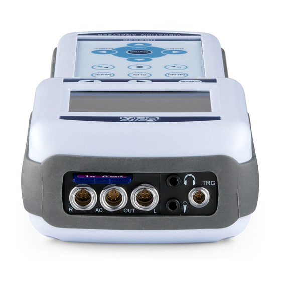
Page 83: Connectors Description
CONNECTORS DESCRIPTION Front panel connectors The following figure indicates the connectors in the HD2070 front panel. Right connector Identified with R letter, it is a male connector with 4 poles LEMO-B type for the connection of a triaxial or monoaxial accelerometer with integrated electronics (IEPE type or compatible). The pin numbering is seen from outside. - Page 84 Jack (Ø3.5mm) type input pin for the microphone. Ground Audio Signal Bottom panel connectors Following is the description of the connectors present in the bottom panel of the HD2070. Power supply connector Male connector for external power supply (∅ 5.5mm-2.1mm pin). It requires a 9…12Vdc/300mA power supply.
- Page 85 USB Connector USB connector type B for the connection of the vibration analyzer to the USB port of a PC with CP22 code cable. The pin numbering is seen from outside. DESCRIPTION +5Vdc Data - Data + Ground...
-
Page 86: Technical Specifications
It is possible to connect triaxial or monoaxial accelerometers with integrated electronics (IEPE type or equivalent). The accelerometers are current supplied with a polarization voltage of 25V and a maximum current of 2mA. With the HD2070 analyzer can be sup- plied the following accelerometers:... -
Page 87: Metrological Specifications
ETROLOGICAL SPECIFICATIONS The HD2070 vibrations analyzer can perform measurement on the hand-arm system, the whole body or vibrations transmitted by the buildings. The weighting filters and the frequency range of the filters with constant percentage octave or third-octave band depend on the cho- sen analysis mode. - Page 88 Central frequencies range Application Octave bands Third-octave bands [Hz] Hand-Arm 4 ÷ 2000 3.15 ÷ 3150 Whole body 0.5 ÷ 250 0.315 ÷ 315 Building vibration 0.5 ÷ 250 0.315 ÷ 315 Self generated noise The intrinsic noise, for the different frequency ponderations and for constant percentage bands, both in octave and third-octave, is measured short-circuiting the input channels.
- Page 89 For Whole-Body measurements, the detected values are indicated in the following tables: WHOLE BODY Weightings [uV] Central Frequency octave bands [Hz] Self generated Noise [uV] Central Frequency third-octave bands 0.32 0.63 1.25 [Hz] Self generated Noise [uV] Central Frequency third-octave bands 12.5 [Hz] Self generated Noise...
-
Page 90: Electrical Features
Integration Time The integration time can be set from a minimum of 1s to a maximum of 99 hours. Crosstalk The crosstalk between channels is <100dB@1kHz. Reference conditions The measure range is the one with input gain equal to 10dB. •... -
Page 91: Statistical Analysis
• Type: USB 1.1 o 2.0 with 500mA • TATISTICAL NALYSIS Statistical analysis, available with HD2070.O2 option, is calculated on the chosen profile screen descriptor (Menu >> Parameters >> Vibration Analyzer >> Profile). Analysis is made with: 1s sampling. •... -
Page 92: Visualization
1,2 and 3 channels. time profile of a parameter at choice with sampling time from 1s to 1 hour. Octave or third-octave spectrum. (option HD2070.O1) probability distribution of levels in 1dB classes. (option HD2070.O2) Graph of the percentile levels from L to L . -
Page 93: Accelerometers Technical Features
CCELEROMETERS TECHNICAL FEATURES The HD2070 analyzer can be supplied with the following monoaxial accelerometers: HDD3200B5T Model Type: Dytran production accelerometer with integrated electron- ics (LIVM ). This sensor is usually used for hand–arm measurements when extremely high vibration levels at high frequency need to be measured or for shock mea- surements. - Page 94 HDP352C34 Model Type: PCB Piezotronics production accelerometer with inte- grated electronics (ICP ). This sensor is normally used for whole body measurements. Sensitivity: 100 mV/g Measure range: ±500 m/s Frequency response (±5%): 0.5 Hz ÷ 10 kHz Resonance frequency: 50 kHz Linearity: 1% F.S.
- Page 95 The HD2070 analyzer can be supplied with the following triaxial accelerometers: HDP356B20 type Type: PCB Piezotronics production triaxial accelerometer with integrated electronics (ICP ). This sensor is normally used for hand-arm measurements. Sensitivity: 1 mV/g Measure range: ±50000 m/s Frequency response (±5%): 2 Hz ÷...
- Page 96 Included accessories: • Screw: double thread 10-32 UNF in copper-beryllium alloy (HD6200) Cable (not included): HD2030.CAB3S-xM (3m, 5m e 10m) to connect accele- rometer to analyzer. HDP356A02 type Type: PCB Piezotronics production triaxial accelerometer with integrated electronics (ICP ). This sensor is normally used for hand-arm measurements.
- Page 97 • Screw: double thread 5-40 UNC and 10-32 UNF in copper- beryllium alloy (081A90) • Screw: double thread 5-40 UNC and M3 in copper-beryllium al- loy (M081A27) Cable (not included): HD2030.CAB3S-xM (3m, 5m e 10m) to connect accele- rometer to analyzer. HDP356A22 type Type: PCB Piezotronics production miniature triaxial accelero-...
- Page 98 • Material: titanium • Isolation: connector coupled with the ground terminal Included accessories: • Cable: HD2030.CAB3-3M (3m) to connect accelerometer to ana- lyzer. HDP356B18 type Type: PCB Piezotronics production triaxial accelerometer with integrated electronics (ICP ). This sensor is normally used for whole body buildings transmitted vibration mea- surements.
- Page 99 Cable (not included): HD2030.CAB3-xM (3m, 5m e 10m) to connect accelero- meter to analyzer. Accessories Whit the accelerometers, the following accessories are supplied as optionally: • HD6188: tube of hydro-repellent silicone grease and electrically insulating. • HD6273: tray with bonding wax. •...
-
Page 100: Reference Standards
REFERENCE STANDARDS ISO 8041:2005 “Human response to vibration – Measuring instrumentation” ISO 5349-1:2001 “ Mechanical vibration – Measurement and evaluation of human expo- sure to hand-transmitted vibration – General requirements” ISO 5349-2:2001 “ Mechanical vibration – Measurement and evaluation of human expo- sure to hand-transmitted vibration –... -
Page 101: Order Codes
HD2070.SL: Kit HD2070 "Safety in the Workplace" for the measurement of noise and vibration in the workplace. The kit consists of HD2070 three-axes vibration analyzer with accelerometers to measure the vibra- tion transmitted to the hand-arm and whole body and HD2010UC/A type 1 sound level meter and analyzer. - Page 102 UNI 9432/11 and ISO9612/11. HD2070.RV: Kit HD2070 "Noise and Vibration" for the measurement of noise and vibration in the workplace and for the assessment of noise pollution and environmental noise in general. The kit consists of...
- Page 103 (triaxial) analyzer input using HD2030.CAB13 and HD2030CAB1B-xM (not included). HDD3019A1: Dytran production accelerometer with integrated electronics (LIVM ) for hand-arm vibration measurements. Sensitivity 10 mV/g, measure range ±5000 m/s . Mounting screw included. Can be connected to left (mo- noaxial) vibration analyzer input using HD2030.CAB1-xM cable or to right (triaxial) analyzer input using HD2030.CAB13 and HD2030CAB1B-xM (not included).
- Page 104 HDP356B18: PCB Piezotronics production triaxial accelerometer with integrated elec- tronics (ICP ) for vibration measurements in buildings. Sensitivity 1 V/g, measure range ±50 m/s . Mounting screws 10-32 UNF and M6 included. Can be connected to the right (triaxial) analyzer’s input using the HD2030.CAB3S-xM cable (not included).
- Page 105 • Steel support with three feet and leveling device. It has a 10-32 UNF threaded hole on the upper surface and a cavity on the bottom side with M4 threaded hole. • Cubic adapter to be mounted on the upper surface through two M4 screws (included).
- Page 106 Accelerometers mounting accessories HD6188: Tube of hydro-repellent silicone grease and electrically insulating. HD6273: Tray with bonding wax. 080A90: quick mounting glue 081B05: Copper-beryllium alloy screw with dual threading 10-32 UNF. 081A27 Double thread screw 5-40 UNC. 081A90: Double thread screw 5-40 UNC and 10-32 UNF (copper-beryllium alloy).
- Page 107 Cables for monoaxial accelerometers HD2030.CAB13: cable for the connection of three monoaxial accelerometers to the triaxial input of the HD2070 analyzer, compete with connectors. 40 cm length with BNC connectors. It is necessary to use a HD2030.CAB1B-xM cable for each accelerometer.
-
Page 108: How To Solve The Problems
This operation does not cancel the content of the data memory. With the instrument switched off, turn on the HD2070 keeping the ENTER key pressed. All the parameters present in the menu are simultaneously set to the factory default. -
Page 109: Keyboard Description
The instrument switching on and off can be done pressing, for at least a second, the ON/OFF key. At startup the analyzer briefly shows the Delta Ohm logo and the program ver- sion. Then it is requested to select the configuration for the sensor connected to the input. - Page 110 MC installed and ready. Size: 500MB RD/WR Press RD/WR to enable all the reading and writing functions and proceed with the selec- tion of the configurations. Before switching off the instrument, it is necessary to stop the current measurement pressing the STOP key. Otherwise a message requesting to stop the current measurement, appears: WARNING! Stop measurement...
- Page 111 MODE Key The MODE key selects in sequence the different analyzer visualization modes, switching from VLM to temporal profile, to the octave or third-octave spectra (option HD2070.O1), to the probability distribution and the percentiles levels (option HD2070.O2). All the working modes are simultaneously active even if they are not visualized: using the MODE key it is possible to choose the visualization mode without affecting the acquisition.
- Page 112 PAUSE/CONTINUE Key The PAUSE key stops the calculation of the integrated measures (Leq, the maximum and minimum level, the spectra, etc.) and the eventual recording. The instant levels continues to be measured and visualized in the VLM screen. To start again the measurement, press again the PAUSE/CONTINUE key.
- Page 113 LEFT arrow Key In the menu, the LEFT arrow key moves the cursor on the left during the input of a character. After the modification of a parameter of the menu, it goes back to the selection of the whole line in order to move among the various items. It compresses (ZOOM-) the vertical scale of the time profile and frequency spectra.
- Page 114 The LEFT arrow key moves on the left the cursor or the two active cursors (blinking). In VLM mode, it allows to scroll the VLM_1, …, VLM_4 screens. In working mode as spectrum analyzer (HD2070.O1 option required), the left and right cur- sor keys allow to switch from acceleration to speed or displacement visualization.
-
Page 115: Appendix
APPENDIX A1. MEASURE PARAMETERS OF HD2070 In the following paragraphs are indicated the acoustic levels with the related abbrevia- tions used to identify them that can be visualized numerically or graphically and memorized. EVELS NUMERICALLY DISPLAYED Frequency weightings Application Weight DESCRIPTION Filter with a flat frequency response. - Page 116 Integrated values in the measurement time Broadband PARAMETER ABBREV. DEFINITION Pkmx Aw,pkmax Maximum peak of weighted acceleration aw, T Linear Average in the measurement time of weighted Linear Average acceleration aw,1s max Maximum exponential average in 1 second of weighted A1smx Exponential Average acceleration...
- Page 117 Integrated values in the measurement time Broadband PARAMETER ABBREV. DEFINITION Aw,pkmax Pkmx Maximum peak of weighted acceleration aw, T Linear average in the measurement time of weighted Linear Average acceleration aw,1s max Maximum Exponential Average in 1 second of the A1smx Exponential Average weighted acceleration...
-
Page 118: A2. Memory Capacity During The Recording Function
A2. MEMORY CAPACITY DURING THE RECORDING FUNCTION The following table reports the indicative values of the storage capacity of the HD2070 analyzer in the different recording modes, expressed as the necessary time to fill the internal flash memory or as the number of recordings. The internal memory of the analyzer is 8MB. - Page 119 For a comparison, in the following table are reported the indicative values of the storage capacity with a 1GB memory card. Memory Mode Description capacity Spectral analysis in octave bands 65000 Single record and au- tomatic recording Spectral analysis in third octave bands 65000 Profile recording Profile interval = 1s...
-
Page 120: A3. Communication Protocol
A3. COMMUNICATION PROTOCOL The commands are made by ASCII strings with variable length ending with CR-LF. The instrument always gives an answer when it receives a command. If the command is not accepted, the answer string is always NAK-CR-LF. It is possible to deactivate the answer, when it is not explicitly requested by the command, acting on VERBOSE parameter (see PAR paragraph). -
Page 121: Par Group (Parameters)
(PARAMETERS) GROUP The following table indicates the key list of PAR group Format Description INSTR_MODEL Instrument model – NOT CHANGEABLE INSTR_NUMBER Instrument serial number - NOT CHANGEABLE INSTR_VERSION Instrument version - NOT CHANGEABLE RIGHT_CONFIG Configuration number of right input (1÷9, 0 means that the channel is not active). - Page 122 Format Description COEFF_3 Axis 3 coefficient for the calculation of the vector HIGH_PASS Activation high-pass filter 0.6Hz 1_AXIS_PARAMETER Parameter 1 single axis (see parameter list) 2_AXIS_PARAMETER Parameter 2 single axis (see parameter list) 3_AXIS_PARAMETER Parameter 3 single axis (see parameter list) 1_VEC_PARAMETER Parameter 1 vector (see parameter list) 2_VEC_PARAMETER...
- Page 123 Parameter Value ALKALINE BATT_TYPE NiMH PRINT_MODE VLM+SPC TRG_OUT_POLARITY 1.2k 2.4k BAUD_RATE 4.8k 9.6k 19.2k 38.4k 57.6k 115.2k FLASH MEM_TYPE CARD RS232 DEVICE VIB_MODE INPUT_GAIN SING INT_MODE MULT MEAS_UNIT cm/s ft/s in/s SPECT_TYPE SPECT_ORDER SPECT_INTEGRATION PROFILE DLOG_TYPE FULL DLOG_ADC_SAMPLES 1234...
-
Page 124: Key Group
KEY GROUP The following table indicates the commands list of KEY group Command Format Description It switches off the instrument HOLD HOLD key MENU MENU key CHN key MODE MODE key PAUSE PAUSE/CONTINUE key STORE It simulates the pressure for more than 2 seconds of the REC key START START/STOP key... -
Page 125: Stt (Status) Group
It visualizes the VLM screen related to a single axis VLM_VECTOR It visualizes the VLM screen related to the vector PROFILE It visualizes the PROFILE screen OCTAVE It visualizes the SPECTRUM screen (option HD2070.O1 required) PROB_DISTR It visualizes the STATISTIC screen (option HD2070.O2 required) CUMUL_DISTR... -
Page 126: Dmp (Dump) Group
The syntax of the setup reading command is: STT:SETUP:LOAD:<# setup> The specified setup is loaded into the instrument. The syntax of the setup storage command is: STT:SETUP:STORE:<# setup>:<title (max 21 characters)> The current setup is memorized, with title, in the specified position. The setup number must be chosen in the interval 1÷10. - Page 127 A sensor configuration is performed with the following commands sequence: • CNF:PROD:R:<#configuration>:<manufacturer (max 10 characters)>\r\n Set the sensor manufacturer • CNF:MODL:R:<#configuration >:<model (max 10 characters)>\r\n Set the sensor model. • CNF:MATR:R:<#configuration>:<serial number (max 10 characters)>\r\n Set the serial number of the sensor •...
-
Page 128: A4. Weighting Filters
A4. WEIGHTING FILTERS Frequency responses of the weighting filters are reported hereafter: for each filter are shown (curve 2) responses and corresponding band-pass filter F (curve 1) including the toler- ances allowed by the technical standard. Weighting filter Wb Filter for whole body vertical acceleration measurement (axis Z) for seating, standing or supine persons (ISO 2631-4) Frequency [Hz]... - Page 129 Weighting filter Wc Filter for whole body horizontal acceleration measurement (X axis) transmitted from seat back to seated persons (ISO 2631-1) Frequency [Hz] Weighting filter Wd Filter for horizontal whole body acceleration measurement (X or Y axes) for seated, standing or supine persons (ISO 2631-1) Frequency [Hz]...
- Page 130 Weighting filter We Filter for angular whole body acceleration measurement (all directions) for seated persons (ISO 2631-1) Frequency [Hz] Weighting filter Wh Filter for hand-arm system transmitted vibration measurement (all directions) (ISO 5349-1) Frequency [Hz]...
- Page 131 Weighting filter Wj Filter for head vertical acceleration measurement (X axis) for supine persons (ISO 2631-1) Frequency [Hz] Weighting filter Wk Filter for whole body vertical vibration measurement (Z axis) for seated, standing or supine persons (ISO 2631-1) Frequency [Hz]...
- Page 132 Weighting filter Wm Filter for building transmitted acceleration on persons (all directions) (ISO 2631-2) Frequency [Hz]...
-
Page 133: Notes About The Operation And User Safety
NOTES ABOUT THE OPERATION AND USER SAFETY Authorized use Observe the technical specifications indicated in the chapter “TECHNICAL FEATURES”. It is au- thorized only the use in compliance with the instructions indicated in this manual. Any other use is to be considered not authorized. General safety instructions This instrument was built and checked in compliance with the EN 61010-1 safety rules for the electronic measurement instruments and left the factory in perfect technical safety conditions. -
Page 134: Table Of Contents
DESCRIPTION OF DISPLAY MODES ................10 VLM S ......................13 CREEN ......................15 ROFILE CREEN HD2070.O1) ................. 16 PECTRUM CREEN OPTION HD2070.O2 ) ..........18 ISTRIBUTION OF ROBABILITY CREEN OPTION HD2070.O2) ..............19 ERCENTILES CREEN OPTION APPLICATIONS ......................20 ....................... 20 ...................... - Page 135 ....................108 ARIOUS ROBLEMS KEYBOARD DESCRIPTION ..................109 APPENDIX ......................115 A1. MEASURE PARAMETERS OF HD2070 ..............115 ................115 EVELS NUMERICALLY DISPLAYED A2. MEMORY CAPACITY DURING THE RECORDING FUNCTION ........118 A3. COMMUNICATION PROTOCOL ................120 (PARAMETERS) ................... 121 GROUP KEY GROUP ......................
- Page 136 All DELTA OHM instruments have been subjected to strict tests and are guaranteed for 24 months from date of purchase. DELTA OHM will repair or replace free of charge any parts which it considers to be ineffi- cient within the guarantee period. Complete replacement is excluded and no request of damages are recognized.
Need help?
Do you have a question about the HD2070 and is the answer not in the manual?
Questions and answers