
Subscribe to Our Youtube Channel
Related Manuals for Delta OHM HD2102.1


Summary of Contents for Delta OHM HD2102.1
-
Page 1: Operating Manual
English Operating manual Photo-radiometers HD2102.1 – HD2102.2 Companies / Brands of GHM www.deltaohm.com Keep for future reference. -
Page 2: Table Of Contents
CONTENTS INTRODUCTION ..............................3 KEYBOARD AND MENU DESCRIPTION ......................8 THE PROBES ................................14 LP 471 P-A ..........................15 OMBINED PROBE LP 471 A-UV ........................15 OMBINED PROBE LP 471 PYRA 02 LP 471 PYRA 03 ....................15 ROBES LP 471 S -PYRA ..........................16 ROBE ILICON .............................17... -
Page 3: Introduction
RS232C serial port or USB 2.0 port. The storing interval, printing, and baud rate can be configured using the menu. The HD2102.1 and HD2102.2 models are fitted with an RS232C serial port and can transfer the acquired measurements in real time to a PC or to a portable printer. - Page 4 Photo-Radiometer HD2102.1 - 4 - HD2102 V2.3...
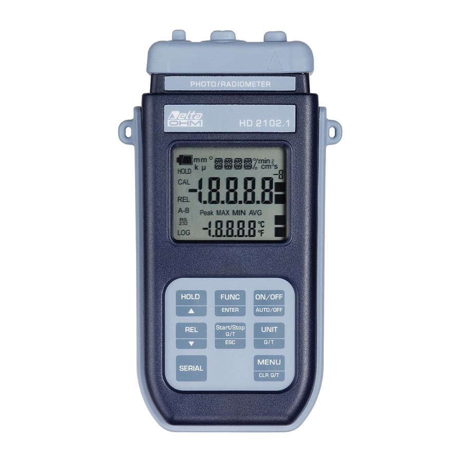
- Page 5 HD2102.1 1. Input for probes, 8-pole DIN45326 connector. 2. External auxiliary power supply connector input. 3. Battery symbol: displays the battery charge level. 4. Function indicators. 5. Secondary display line. 6. HOLD/ key: freezes the measurement during normal operation; in the menu, increases the current value.
- Page 6 Photo-Radiometer HD2102.2 - 6 - HD2102 V2.3...
- Page 7 HD2102.2 1. Input for probes, 8-pole DIN45326 connector. 2. External auxiliary power supply connector input. 3. Battery symbol: displays the battery charge level. 4. Function indicators. 5. Secondary display line. 6. HOLD/ key: freezes the measurement during normal operation; in the menu, increases the current value.
-
Page 8: Keyboard And Menu Description
The instrument keyboard is composed of single-function keys, like the SERIAL key in the HD2102.1 model, and double-function keys such as the ON-OFF/Auto-OFF key. In the double-keys, the function in the upper part is the “main function”, while the one in the bottom part is the “secondary function”. - Page 9 The automatic turning off function is disabled when external power is used. On the other hand, it cannot be disabled when the batteries are discharged. FUNC/ENTER key During normal measurement this enables the display and logging of the maximum (MAX), minimum (MIN) and average (AVG) value of the measurements captured by the probe connected to the instrument, updating them with the acquisition of new samples.
- Page 10 This setting changes the information displayed and the immediate print of data (SERIAL key). The data recorded using the LOG function (HD2102.2) and sent to the printer or PC through the serial port using the SERIAL function (HD2102.1 and HD2102.2), keep the chosen and displayed unit of measurement.
- Page 11 MENU - CLR Q/T key The first menu item is accessed by initially pressing on the MENU key; press ENTER to go to the following items. To modify the item displayed, use the arrow keys ( ). The current value is confirmed by pressing the ENTER key and the display moves on to the next parameter, by pressing the ESC key the set-up is cleared.
- Page 12 8. YEAR: to set the current year. Use the arrows to modify this parameter and confirm using ENTER. 9. MNTH (month): to set the current month. Use the arrows to modify this parameter and confirm using ENTER. 10. DAY: to set the current day. Use the arrows to modify this parameter and confirm using ENTER.
- Page 13 LOG key: the transfer of the data contained in the instrument internal memory via the serial port is started. Please, see the paragraph dedicated to data transfer on page 25. SERIAL key - only HD2102.1 SERIAL/EraseLOG key - only HD2102.2 In measurement mode, this function starts and stops the data transfer to the RS232C serial output.
-
Page 14: The Probes
• global solar irradiance in the spectral range 300…3000 nm. Probe consisting of a first class pyranometer LP PYRA 02 and cable with SICRAM module (LP 471 PYRA 02). Note 1: the combined probes LP 471 P-A and LP 471 A-UVeff work with instruments HD2102.1 and HD2102.2 having firmware version respectively “HD2102.11” and “HD2102.21” and following. -
Page 15: Combined Probe Lp 471 P-A
LP 471 P-A OMBINED PROBE LP 471 P-A is a two sensors combined probe with SICRAM module for measuring illuminance (lux) with standard photopic spectral response and irradiance (μW/cm ) in UVA spectral range (315...400 nm, with peak at 365 nm). Moreover probe provides the ratio of UVA irradiance and illuminance in µW/lumen (quantity of interest in the museums field). -
Page 16: Probe Lp 471 Silicon -Pyra
LP 471 S -PYRA ROBE ILICON LP 471 Silicon-PYRA measures the global solar radiation using a silicon photodiode in the spectral range 400…1100 nm. The particular geometry and the diffuser allows the sensor to have a field of view of 180° according to the cosine law. -
Page 17: Q/Time Integration
IME INTEGRATION In addition to instantaneous measurement, the instrument calculates the following summation: Σ ⋅Δ Δt = 1sec Q(t) = u(t) t, where u(t) is the instantaneous value of the input variable compared to time t. The sampling interval is fixed at 1 second. As soon as either the Q(t) value or the integration time t reach the set limit, the integration is stopped. -
Page 18: Warnings And Operating Instructions
WARNINGS AND OPERATING INSTRUCTIONS 1. Do not bend the probe connectors or force them upward or downward. 2. Do not bend or force the contacts when inserting the probe connector into the instrument. 3. The sensors and filters should not exceed the temperature limits established with consequent irreparable degradation of their characteristics. -
Page 19: Instrument Signals And Faults
INSTRUMENT SIGNALS AND FAULTS The following table lists all error indications and information displayed by the instrument and supplied to the user in different operating situations: Display indications Explanation This appears if the probe has already been detected by the instrument, but is disconnected. - Page 20 The following table reports the indications provided by the instrument as they appear on the display, together with their description. Display indications Explanation >>>_LOG_DUMP_or_ERAS transfer or erase data battery discharged - replace it immediately BATT TOO LOW - CHNG NOW baud rate value BAUDRATE >>>...
-
Page 21: Low Battery Warning And Battery Replacement
LOW BATTERY WARNING AND BATTERY REPLACEMENT The battery symbol on the display constantly shows the battery charge status. To the extent that batteries have discharged, the symbol "empties". When the charge decreases still further it starts blinking… In this case, batteries should be replaced as soon as possible. If you continue to use it, the instrument can no longer ensure correct measurement. -
Page 22: Instrument Storage
ALFUNCTIONING UPON TURNING ON AFTER BATTERY REPLACEMENT After replacing the batteries, the instrument may not restart correctly; in this case, repeat the operation. After disconnecting the batteries, wait a few minutes in order to allow circuit condensers to discharge completely; then reinsert the batteries. ARNING ABOUT BATTERY USE •... -
Page 23: Serial Interface And Usb
SERIAL INTERFACE AND USB The HD2102.1 and HD2102.2 instruments are fitted with an electrically isolated RS-232C serial interface; the HD2102.2 also has an USB 2.0 interface. The following serial cables can be used: • HD2110CSNM: serial connection cable with 8-pole MiniDin connector on one end and 9-pole Sub D connector on the other end;... - Page 24 Command Response Description Firm.Date=2004/06/15 Firmware date cal 0000/00/00 00:00:00 Calibration date and time Probe=Sicram RAD Type of probe connected to input Probe SN=11119999 Probe serial number Probe cal.=2004/01/12 Probe calibration date User ID=0000000000000000 User code (set with T2xxxxxxxxxxxxxxxx) Print instrument's heading Stop printing data PRINTOUT IMMEDIATE Immediate printing of data...
-
Page 25: Storing And Transferring Data To A Personal Computer
STORING AND TRANSFERRING DATA TO A PERSONAL COMPUTER The HD2102.1 and HD2102.2 instruments can be connected to a personal computer via an RS232C serial port or USB 2.0 port, and exchange data and information through the DeltaLog9 software running in a Windows operating environment. Both models can send in real time input measured values directly to a PC, through the SERIAL function;... -
Page 26: The Print Function
• Some keys are disabled during logging. The following keys work: HOLD, FUNC (Max-Min- Avg) and SERIAL. • Pressing the HOLD, REL and FUNC keys has no effect on the logged data if these keys are pressed after starting the recording, otherwise the following is valid. •... -
Page 27: Connection To A Pc
SERIAL PORT OF THE INSTRUMENT 1. The measurement instrument must be switched off. 2. Using the Delta Ohm HD2110CSNM or C.206 cable, connect the measurement instrument to the first free RS232C (COM) or USB serial port of the PC. 3. Turn on the instrument and set the baud rate to 38400 (MENU >> ENTER until the Baud Rate parameter >>... -
Page 28: Notes About Working And Operative Safety
NOTES ABOUT WORKING AND OPERATIVE SAFETY Authorized use The technical specifications as given in chapter "TECHNICAL CHARACTERISTICS" must be observed. Only the operation and running of the measuring instrument according to the instructions given in this operating manual is authorized. Any other use is considered unauthorized. General safety instructions This measuring system is constructed and tested in compliance with the EN 61010-1:2010 safety regulations for electronic measuring instruments. -
Page 29: Instrument Technical Characteristics
INSTRUMENT TECHNICAL CHARACTERISTICS Instrument Dimensions (Length x Width x Height) 185x90x40mm Weight 470g (complete with batteries) Materials ABS, rubber Display 2x4½ characters plus symbols Visible area: 52x42mm Operating conditions Operating temperature -5…50°C Storing temperature -25…65°C Working relative humidity 0…90%RH without condensation Protection degree IP66 Power Supply... - Page 30 USB interface - model HD2102.2 Type 1.1 - 2.0 electrically isolated Connections Input module for the probes 8-pole male DIN45326 connector RS232 serial interface 8-pole MiniDin connector USB interface (only HD2102.2) Mini-USB type B connector Mains adapter (cod. SWD10) 2-pole connector (positive at centre) - 30 - HD2102 V2.3...
-
Page 31: Technical Characteristics Of Photometric And Radiometric Probes
ECHNICAL CHARACTERISTICS OF PHOTOMETRIC AND RADIOMETRIC PROBES SICRAM COMPLETE WITH MODULE TO BE CONNECTED IN LINE WITH THE INSTRUMENT ILLUMINANCE probe LP 471 PHOT complete with SICRAM module and equipped with the instrument Measurement range (lux): 0.01…199.99 …1999.9 …19999 …199.99⋅10 Resolution (lux): 0.01 0.01⋅10... - Page 32 Quantum radiometric probe for the measurement of the photon flow across the chlorophyll range PAR LP 471 PAR complete with SICRAM module in line with the instrument 0.01… 199.99 200.0…1999.9 2000…10000 Measurement range (μmol/m 0.01 Resolution (μmol/m Spectral range: 400nm…700nm Calibration uncertainty: <5% (response according to the cosine law):...
- Page 33 IRRADIANCE probe LP 471 RAD complete with SICRAM module in line with the instrument Measurement range (W/m 1.000…19.999 20.00…199.99 200.0…1999.9 0.1⋅10 … 999.9⋅10 Resolution (W/m 0.1⋅10 0.001 0.01 Spectral range: 400nm…1050nm Calibration uncertainty: <5% (response according to the cosine law): <6% (linearity): <1%...
- Page 34 IRRADIANCE probe LP 471 UVA complete with SICRAM module in line with the instrument Measurement range (W/m 1.000…19.999 20.00…199.99 200.0…1999.9 0.1⋅10 … 999.9⋅10 Resolution (W/m 0.001 0.01 0.1⋅10 Spectral range: 315nm…400nm (Peak 360nm) Calibration uncertainty: <5% (response according to the cosine law): <6% (linearity): <1% ±1digit...
- Page 35 IRRADIANCE probe LP 471 UVB complete with SICRAM module in line with the instrument Measurement range (W/m 1.000…19.999 20.00…199.99 200.0…1999.9 0.1⋅10 … 999.9⋅10 Resolution (W/m 0.1⋅10 0.001 0.01 Spectral range: 280nm…315nm (Peak 305 - 310 nm) Calibration uncertainty: <5% (response according to the cosine law): <6% (linearity): <2% ±1digit...
- Page 36 IRRADIANCE probe LP 471 UVC complete with SICRAM module in line with the instrument Measurement range (W/m 1.000…19.999 20.00…199.99 200.0…1999.9 0.1⋅10 … 999.9⋅10 Resolution (W/m 0.1⋅10 0.001 0.01 Spectral range: 220nm…280nm (Peak 260nm) Calibration uncertainty: <5% (response according to the cosine law): <6% (linearity): <1%...
- Page 37 The good accordance between the two curves enables the instrument to take reliable measurements of different types of lamps (and filters) used at present for tanning devices. Each probe is individually calibrated at Delta Ohm photo-radiometry laboratory by means of a double monochrome. Calibration is performed at 295 nm through a calibrated reference photodiode.
- Page 38 EFFECTIVE IRRADIANCE probe in the spectral range of Blue light LP 471 BLUE complete with SICRAM module in line with the instrument Measurement range (W/m 1.000…19.999 20.00…199.99 200.0…1999.9 0.1⋅10 … 999.9⋅10 Resolution (W/m 0.001 0.01 0.1⋅10 Spectral range: 380 nm…550 nm. Blue hazard action curve B(λ). Calibration uncertainty: <10% (response according to the cosine law): <6%...
- Page 39 Two sensors combined probe LP 471 P-A for ILLUMINANCE and UVA IRRADIANCE measurement complete with SICRAM module, in line with the instrument Illuminance Measurement range (lux): 0.01…199.99 …1999.9 …19999 …199.99⋅10 Resolution (lux): 0.01 0.01⋅10 Spectral range: according to photopic curve V(λ) α...
- Page 40 Combined probe LP 471 A-UVeff for measuring TOTAL EFFECTIVE IRRADIANCE ) according to UV weighting curve (CEI EN 60335-2-27), complete with SICRAM module, in line with the instrument Total effective irradiance Measurement range (W 0.001… 19.999 Resolution (W 0.001 Spectral range: UV action curve for erythema measurement (250 nm…400 nm) See fig.1.
- Page 41 Measuring probe LP 471 SILICON-PYRA of GLOBAL SOLAR IRRADIANCE complete with SICRAM module in line with the instrument Measurement range (W/m 1.000…19.999 20.00…199.99 200.0…1999.9 0.1⋅10 … 999.9⋅10 Resolution (W/m 0.001 0.01 0.1⋅10 Spectral range: 400 nm…1100 nm Calibration uncertainty: <3% (response according to the cosine law): <3% (linearity): <1%...
-
Page 42: Order Codes
ORDER CODES HD2102.1 Kit including the instrument HD2102.1, 4 x 1.5V alkaline batteries, operating manual, case and DeltaLog9 software. HD2102.2 Kit including the HD2102.2 datalogger, 4 x 1.5V alkaline batteries, operating manual, case and DeltaLog9 software. The probes and the cables for the connection to the PC or printer must be ordered separately. - Page 43 LP 471 UVB Radiometric probe for IRRADIANCE measurement complete with SICRAM module, in the 280nm…315nm, peak 305-310 nm, UVB spectral range, quartz diffuser for cosine correction. Measurement range: 0.1⋅10 …2000 W/m LP 471 UVC Radiometric probe IRRADIANCE measurement 220nm…280nm UVC spectral range, complete with SICRAM module, peak 260nm, quartz diffuser for cosine correction.
- Page 44 They can supply calibration certificates for the accredited quantities. Note 1: probes LP 471 P-A and LP 471 A-UVeff work with instruments HD2102.1 and HD2102.2 having firmware version respectively “HD2102.11” and “HD2102.21” and following. On the back of these instruments a label shows version and date of the firmware.
- Page 45 OTES - 45 - HD2102 V2.3...
- Page 46 OTES - 46 - HD2102 V2.3...
-
Page 48: Serial Number
All DELTA OHM instruments are subject to accurate testing, and are guaranteed for 24 months from the date of purchase. DELTA OHM will repair or replace free of charge the parts that, within the warranty period, shall be deemed non efficient according to its own judgement. Complete replacement is excluded and no damage claims are accepted. - Page 49 GHM GROUP – Delta OHM | Delta Ohm S.r.l. a socio unico Via Marconi 5 | 35030 Caselle di Selvazzano | Padova | ITALY Phone +39 049 8977150 | Fax +39 049 635596 www.deltaohm.com | info@deltaohm.com The quality level of our instruments is the result of the constant development of the product. This may produce some differences between the information written in this manual and the instrument you have purchased.
- Page 50 GHM GROUP – Delta OHM | Delta Ohm S.r.l. a socio unico Via Marconi 5 | 35030 Caselle di Selvazzano | Padova | ITALY Phone +39 049 8977150 | Fax +39 049 635596 www.deltaohm.com | info@deltaohm.com V2.3 28/08/2017...
Need help?
Do you have a question about the HD2102.1 and is the answer not in the manual?
Questions and answers