Table of Contents
Advertisement
Quick Links
ETC Installation Guide
SC1008 Branch Circuit Emergency Lighting Transfer Switch
Overview
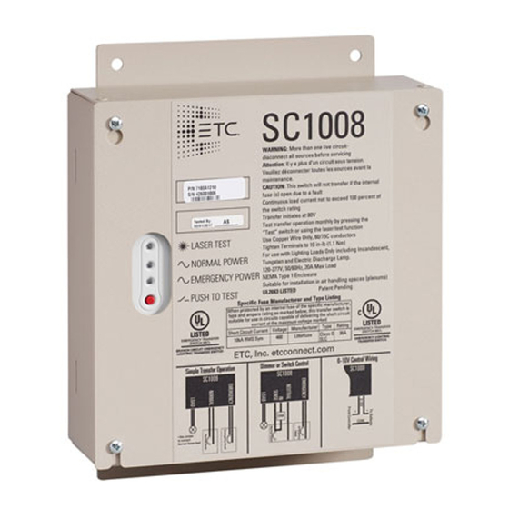
The SC1008 Branch Circuit Emergency Lighting Transfer Switch (BCELTS) transfers a single lighting
circuit from its normal power source to an emergency power source in the event of the loss of normal
power or an external trigger (e.g., fire alarm).
The SC1008 BCELTS includes the following features and functions:
a front panel accessible push–and–hold Test Switch
•
a front panel accessible Laser Test, enabling remote testing with the use of a laser pointer (or
•
similar)
front panel status indicators for Normal Power (green) and Emergency Power (red)
•
a fire alarm dry contact input, which can be set for normally open or normally closed operation
•
an auxiliary relay for 0–10V or Digital Addressable Lighting Interface (DALI) control signals
•
Compliance
The SC1008 meets or exceeds the following regulatory standards:
UL Listed to UL 1008 for Branch Circuit Emergency Transfer Switch Equipment
•
cUL Listed to CSA C22.2 Emergency Transfer Switch Equipment
•
UL Listed to UL 2043 for plenum rated products
•
Complies with ANSI/NFPA 110, Standard for Emergency and Standby Power Systems
•
Satisfies requirements of the National Electrical Code (NFPA 70):
•
Article 700 – Emergency Systems
-
Article 701 – Legally Required Standby Systems
-
Article 702 – Optional Standby Systems
-
Section 518.3(C) – Assembly Occupancies
-
Section 520.7 – Theatres and Similar Locations
-
Section 540.11(C) – Motion Picture Projection Rooms
-
Corporate Headquarters Middleton, WI, USA +1 608 831 4116 London, UK +44 (0)20 8896 1000
Holzkirchen, DE +49 (80 24) 47 00-0 Rome, IT +39 (06) 32 111 683 Hong Kong +852 2799 1220 Paris, FR +33 1 4243 3535
Web
© 2020 ETC Trademark and patent
Product information and specifications subject to change. ETC intends this document to be provided in its entirety.
7180M2180 Rev D Released 2020-10
etcconnect.com
Support
support.etcconnect.com
info: etcconnect.com/ip
Contact
etcconnect.com/contactETC
Advertisement
Table of Contents

Subscribe to Our Youtube Channel
Related Manuals for ETC SC1008 Branch Circuit Emergency Lighting Transfer Switch


Summary of Contents for ETC SC1008 Branch Circuit Emergency Lighting Transfer Switch
- Page 1 Holzkirchen, DE +49 (80 24) 47 00-0 Rome, IT +39 (06) 32 111 683 Hong Kong +852 2799 1220 Paris, FR +33 1 4243 3535 etcconnect.com Support support.etcconnect.com Contact etcconnect.com/contactETC © 2020 ETC Trademark and patent info: etcconnect.com/ip Product information and specifications subject to change. ETC intends this document to be provided in its entirety. 7180M2180 Rev D Released 2020-10...
-
Page 2: Installation Requirements
ETC Installation Guide SC1008 BCELTS Installation Requirements Install the SC1008 in a location that is accessible by qualified personnel for testing of the transfer function using either a laser pointer (or similar) or the onboard test switch. The SC1008 installs to a flat surface, has four conduit entry locations, and includes a universal mounting plate with four mounting holes. -
Page 3: Installation
ETC Installation Guide SC1008 BCELTS Fire Alarm Input The Fire Alarm Input allows power transfer to the emergency power source (if emergency power is present) when triggered by an external system. Note: This transfer is activated even when normal power is still present. -
Page 4: Wire Terminations
ETC Installation Guide SC1008 BCELTS 3. Four knockouts are provided on the right side of the enclosure. Install conduit fittings (provided by others) to the knockout locations. Wire Terminations Simple Transfer The SC1008 can accommodate installations that require a of normal and emergency... -
Page 5: Earth Ground
ETC Installation Guide SC1008 BCELTS Earth Ground Wire and Terminal Specifications on page 4 for specification of wire, strip length, and terminal torque ratings, and then prepare and terminate your earth ground wire to the lug provided in the enclosure. - Page 6 ETC Installation Guide SC1008 BCELTS Dimmed or Switched Load The SC1008 has the ability to separate the sensing of normal power from the load itself; this allows you to have a light switch or dimmer controlling the load when normal power is available, but to have the load transfer to emergency power in the event of normal power loss.
- Page 7 SC1008 BCELTS ETC Control Panel The SC1008 can also handle loads from ETC dimming and relay panels. In some cases, unlike the example on the previous page, the sense hot line cannot be separated prior to the dimmer or relay.
- Page 8 All low–voltage Class 2 wiring must be separated from all Class 1 wiring. Follow local codes and installation restrictions. ETC recommends limiting the distance run for the 0 – 10 V control wiring from the controller to the last ballast (driver) to 300 ft (90 m), based on 18 AWG wire.
-
Page 9: Operation And Test
ETC Installation Guide SC1008 BCELTS Final Installation and Power Up 1. Check that each termination point is secure. 2. Check that the fire alarm contact input switches are set for correct switch operation, either normally open or normally closed. 3. Clear all debris from the inside of the enclosure. -
Page 10: Test Button
In–line fuses are present for the normal power input and the emergency power input. Replace fuses only with Class G SLC 30 A fuses (order ETC part number F392). 1. Disconnect both power supply sources and lock/tag out appropriately. -
Page 11: Troubleshooting
ETC Installation Guide SC1008 BCELTS Troubleshooting When both of the SC1008 LEDs are blinking, the relays need to be manually reset to a known state. WARNING: RISK OF DEATH BY ELECTRIC SHOCK! Failure to disconnect all power to the panel before working inside could result in serious injury or death.
Need help?
Do you have a question about the SC1008 Branch Circuit Emergency Lighting Transfer Switch and is the answer not in the manual?
Questions and answers