Table of Contents
Advertisement
Quick Links
Installation Guide
MBI
M
-B
I
ultI
utton
nterface
S
S
wItch
tatIonS
This install guide covers the Echoflex Solutions Multi-Button Interface switch station,
models and descriptions below.
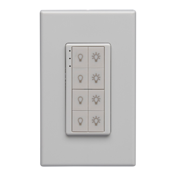
MBI-2*x - Two button - Multi-Button Interface switch station
MBI-4*x - Four button - Multi-Button Interface switch station
MBI-8*x - Eight button - Multi-Button Interface switch station
The character * indicates frequency U= 902MHz, Y= 868 MHz. The character x is
replaced with a color indicator ( W = White, G = Gray, C=Cream, B = Black).
Product Overview
The switch stations communicate wirelessly with Echoflex lighting controllers to control
the internal relay and/or output dimming level. Common switch stations applications
include basic ON/OFF lighting or dimming.
A finger press upon the ON or OFF button transmits the switch event along with a
tactile feel, an audible click and (for the ON button) a LED indication of the event.
Each pair of buttons can be linked to different controllers for multiple circuit control
from one wall station.
The MBI also features Range Confirmation® which provides visual feedback of the
strength of the signal received by the controller, thereby assisting in finding the optimal
placement of the MBI.
The MBI uses 2 buttons for On/OFF operation. The ON button has a light bulb icon
with "light rays" to indicate ON. The OFF button has a light bulb icon without rays,
indicating OFF. The buttons provide both switching and dimming functionality. A quick
press of the button provides switching, a press and hold will dim lights up (ON button)
and down (OFF button) when linked to an Echoflex dimming controller. A double tap
of an ON button when linked to a Echoflex dimming controller will dim the light to full
ON (single tap ON will turn on the lights to the previously set level).
Preparing to Install
Careful consideration should be made when locating the controllers and stations
based on the construction materials in the space and possibility of tenant's furniture
disrupting the transmissions. The station should be installed in the same space as the
controller device controlling the light fixtures or circuits.
The MBI switch stations can be damaged by screw guns over torquing the mounting
screws. Use hand tools when installing.
The MBI switch stations need to be mounted to a firm surface. They can be flush
mounted with the screws and wall anchors (not supplied). Alternately, the station can
be mounted on a mud ring using the provided back support plate.
To mount over line voltage device boxes, please order our UL approved barrier - see
Accessories for order info.
Advertisement
Table of Contents

Subscribe to Our Youtube Channel
Related Manuals for ETC Echoflex MBI-2 Series


Summary of Contents for ETC Echoflex MBI-2 Series
- Page 1 Installation Guide ultI utton nterface wItch tatIonS This install guide covers the Echoflex Solutions Multi-Button Interface switch station, models and descriptions below. MBI-2*x - Two button - Multi-Button Interface switch station MBI-4*x - Four button - Multi-Button Interface switch station MBI-8*x - Eight button - Multi-Button Interface switch station The character * indicates frequency U= 902MHz, Y= 868 MHz.
- Page 2 Installation 1. The MBI comes with a screw-less faceplate. It is designed to stay in place with no rattle and requires some force when mounting or removing. Remove the face plate with a flat blade screw driver, by prying the slot that is located on the center of the bottom edge of the faceplate.
- Page 3 When a button is pressed and a single Red LED blinks, it is an indication that the RPS telegram was transmitted but the battery voltage is low (less than 2.2V). When the Red LED blinks 3 times on a button press the RPS Note: telegram was not transmitted and the battery is critically low (less than 2.0 V)
- Page 4 Reserved for future use This test mode does nothing, returns to normal operation if selected. DEBUG: Test Button Pad This test mode blinks the LEDs when button presses are detected. No transmissions occur during transmissions. Button test mode will timeout after 180s and reboot the unit.
Need help?
Do you have a question about the Echoflex MBI-2 Series and is the answer not in the manual?
Questions and answers