Advertisement
Quick Links
ETC Installation Guide
SmartSwitch to Echo Relay Panel Feedthrough Retrofit Kit
Overview
An existing SmartSwitch can be converted to house the Power Control Processor Mk2 used in Echo
Relay Panel Feedthrough. This processor allows additional functionality such as DALI control,
contact input control, 0-10V control, and Ethernet network connectivity. This guide details the
installation of this retrofit kit into the 24- or 48-position SmartSwitch.
Adding a retrofit kit to a SmartSwitch Relay Panel changes the panel model. With the retrofit kit
installed, the panel becomes an Echo Relay Panel Feedthrough (ERP24-FT or ERP48-FT).
SmartSwitch 24
WARNING:
to the panel before working inside could result in serious injury or death.
AVERTISSEMENT :
panneau sans avoir déconnecté le courant peut entrainer des blessures graves,
voire mortelles.
De-energize main feed to the panel and follow appropriate Lockout/Tagout
procedures as mandated by NFPA 70E or local jurisdiction requirements. It is
important to note that electrical equipment such as breaker panels can present an
arc flash hazard if improperly serviced. This is due to the high amounts of short-
circuit current available on the electrical supply to this equipment. Any work must
comply with OSHA Safe Working Practices or local jurisdiction requirements.
Corporate Headquarters n Middleton, WI, USA | +1 608 831 4116
Global Offices n London, UK | Rome, IT | Holzkirchen, DE | Paris, FR | Hong Kong | Dubai, UAE | Singapore
New York, NY | Orlando, FL | Los Angeles, CA | Austin, TX | © 2023 Electronic Theatre Controls, Inc.
Web
Trademark and patent info:
Product information and specifications subject to change. ETC intends this document to be provided in its entirety.
7023M2120 Rev E Released 2023-07
SmartSwitch 48
RISK OF DEATH BY ELECTRIC SHOCK! Failure to disconnect all power
RISQUE D'ÉLECTROCUTION! Travailler à l'intérieur du
etcconnect.com
| Support
support.etcconnect.com
etcconnect.com/ip
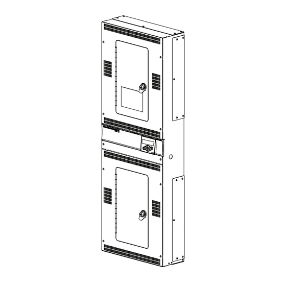
Echo Relay Panel
Feedthrough 24
(ERP24-FT)
| Contact
etcconnect.com/contactETC
| Third-party license agreement
info: etcconnect.com/licenses
Echo Relay Panel
Feedthrough 48
(ERP48-FT)
Advertisement

Related Manuals for ETC SmartSwitch


Summary of Contents for ETC SmartSwitch
- Page 1 24- or 48-position SmartSwitch. Adding a retrofit kit to a SmartSwitch Relay Panel changes the panel model. With the retrofit kit installed, the panel becomes an Echo Relay Panel Feedthrough (ERP24-FT or ERP48-FT).
-
Page 2: Required Tools
Interface) with mounting panel Door and vented door panel Upper relay control card ETC part number 7123B5635 ETC part number 7123B5735 (only used in 48- Lower relay control card position panel) red and blue, 4 for 24-position panel and 8 for 48-... - Page 3 Remove the Door and Front Panel Using the Phillips screwdriver, remove the four M5 screws holding the (top) front panel onto the SmartSwitch. The screws are labeled "A" in the illustration to the right. • Set the screws aside; they will be used to install the new door.
- Page 4 ETC Installation Guide SmartSwitch to ERP-FT Retrofit Kit Disconnect the Wiring SmartSwitch 48 1. Fold out the tabs holding the ribbon cable in place in both the relay interior and the top edge of the user interface. 2. Gently pull the ribbon cable from both headers. This cable is no longer needed and can be discarded.
- Page 5 1. Using the Phillips screwdriver, remove the two M5 screws securing the I/O panel below the Smartswitch User Interface. Open the panel by folding it down. 2. Remove the ground wire from the spade on the I/O panel (A, below).
- Page 6 SmartSwitch to ERP-FT Retrofit Kit Remove the Relay Control Card The relay control card must be replaced as part of the retrofit. A SmartSwitch 24 has one relay control card; a SmartSwitch 48 has two relay control cards, an upper and a lower.
- Page 7 48-position panel contains two cards and uses 26 existing screws. • When upgrading a 48-position panel, identify the upper control card by the white part number sticker with ETC part number 7123B5635. The lower control card is ETC part number 7123B5735.
- Page 8 ETC Installation Guide SmartSwitch to ERP-FT Retrofit Kit Upper Termination Block and Control Card Connections Control power termination block Existing blue and white wires (to transformer) New pair of blue and white wires to power supply Existing blue and white wires to lower termination block (48-position panel only)
- Page 9 1. Locate the termination board provided with the retrofit kit. 2. Use three of the 8-32 x 3/8 inch screws that secured the original SmartSwitch User Interface to the panel to secure the termination board to the interior of the Relay Panel.
- Page 10 ETC Installation Guide SmartSwitch to ERP-FT Retrofit Kit Connect the Harnesses Locate all harnesses included with the retrofit kit. See Included in the Retrofit Kit on page 2 Connect the Termination Board Harness The termination board harness is factory-installed to the termination board at "PWR/COM". Press the white-and-black two-pin connector into the header on the upper relay control card at "CAN"...
- Page 11 The Category 5 surface-mount connector consists of two pieces: a base unit and a cap. The cap has colored markings on one end to indicate where to insert each of the cable’s color-coded wires. Follow the T568B wiring scheme, as illustrated on the cap sticker, for compatibility with ETC network wiring conventions.
- Page 12 ETC Installation Guide SmartSwitch to ERP-FT Retrofit Kit Connect the Patch Cable Connect the patch cable (ETC part (N4036) from the surface-mount connector to the back of the user interface. Surface-mount box and two-part Cat5 connector (included) Building network connection Network patch...
-
Page 13: Connect The Ground Wire
3. Push the other end of the ribbon cable firmly into the user interface header. 4. Clip one retaining clip onto each header to secure each end of the user interface ribbon cable. Two retaining clips are provided (ETC part number HW7519). Note: The locking door is not shown to show the upper connection details. -
Page 14: Option Cards
ETC Installation Guide SmartSwitch to ERP-FT Retrofit Kit Option Cards Install any required option cards. Installation instructions are available in the Echo Relay Panel Feedthrough Installation Manual which is available for free download at etcconnect.com. Primary/Secondary Switch (48-Position Panel Only) -
Page 15: Install The Door
ETC Installation Guide SmartSwitch to ERP-FT Retrofit Kit Example 3: Two Card Configurations (Different Card Types) If you are using two options cards of different types (e.g. one DALI card and one Contact Input card), the following configurations are possible:... -
Page 16: Power Up And Test
Power Control Processor Mk2. Compliance For complete product documentation, including compliance documentation, visit etcconnect.com/products. FCC Compliance SmartSwitch to Unison Echo Retrofit Kit (For any FCC matters): Electronic Theatre Controls, Inc. 3031 Pleasant View Road Middleton, WI 53562 +1 (608) 831-4116 etcconnect.com...
Need help?
Do you have a question about the SmartSwitch and is the answer not in the manual?
Questions and answers