Advertisement
Quick Links
Advertisement

Subscribe to Our Youtube Channel
Related Manuals for Lasita Maja Exeter 2


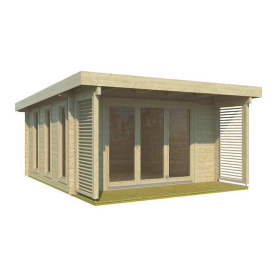
Summary of Contents for Lasita Maja Exeter 2
- Page 1 Exeter 2 Art.No. 7012302 Pystytyskuvat...
- Page 16 3 DOOR BIFOLD DOOR SET...
- Page 17 Hardware Cover cap for stay bearing x 2 6 x 140 mm Screw x 10 Plastic cover x 1 TX 30 3,5 x 40 mm Screw x 54 TX 15 CB rosette inside x 1 Cover cap x 1 RH + x 1 LH PZ 2 M5 x 65 mm Bolt x 2 Plastic push x 6...
-
Page 18: Parts List
Parts list BOTTOM... - Page 19 Door frame assembling q Lay the 4 pcs of frame parts on the floor on top of cardboard or a similar protective material to prevent damage to the parts. TX 30 Tools not supplied! Step 3 6 x 140 mm Screw x 10 Step 1 Step 4 Step 2...
- Page 20 Door frame installation and sideboard fixing TX 15 Tools not supplied! 3,5 x 40 mm Screw x 36 Step 2 Step 1 View from inside 90 v v v v Step 4 Step 3 Step 5 Perform same steps at exterior side...
- Page 21 Door sash no. 1 installation See the page 13 q adjustment of the Turn-Only hinge q adjustment at the rebate corner hinge q adjusting the pivot rest View from inside Step 1 Step 3 Step 2 PUSH UP...
- Page 22 Door sash no. 2 installation See the page 13 q adjusting the fold and slide hinge q see additional document "Installation, operating and maintenance instructions" View from outside Step 1 Step 2 PUSH UP...
- Page 23 Door sash no. 2 installation continued See the page 13 q adjusting the bogie and guide roll q see additional document "Installation, operating and maintenance instructions" View from inside Step 3 remove the cap Step 4 q remove the cap q install after adjustment...
- Page 24 Door sash no. 3 installation See the page 13 q engaging and disengaging the stay q adjusting the stay q adjustment at the rebate corner hinge q adjusting the pivot rest View from inside Step 1 Step 3 Step 2 PUSH UP...
- Page 25 Door handles and lock set installation PZ 2 Tools not supplied! View from inside Step 1 90 v v v v Step 2 View from outside Step 3 outside inside M5 x 65 mm M5 x 50 mm outside outside 180 v v v v inside 90 v v v v...
- Page 26 Cover caps installation View from inside Step 1 Step 2 (RH) (LH)
-
Page 27: Hardware Adjustment
Hardware adjustment TX 15 SW 4 Tools not supplied! Adjustment of the Turn-Only hinge Engaging and disengaging the stay Setting 1 mm ± TX 15 Adjusting the stay Setting + 3,5 mm / -3 mm engage TX 15 disengage Setting + 3,5 mm / -3 mm TX 15 Setting ±1 mm TX 15... - Page 28 Cover caps installation See the page 13 q fixing / removing the sash-hinge cover View from outside Step 1 install cover caps after fine adjustment Step 2...
- Page 29 Operation of bifold doors q First close doors 1 and 2, by turning the inside handle 90 degrees downwards so the doors then lock. q Close door 3 by turning handle 90 degrees downwards, for locking turn the key clockwise. Turn the handle 180 degrees to tilt-open door 3.
- Page 30 Installation, operating and maintenance instructions Installing the Fold&Slide sashes As a prerequisite for installing the Fold&Slide sashes, the Fold&Slide sash with frame hinges on the frame side must already be installed and correctly adjusted (for NOTE more information see the corresponding profi le-specifi c installation drawing for Turn-Only or Tilt&Turn hardware).
- Page 31 Installation, operating and maintenance instructions Push the upper pivot-rest of the Fold&Slide sash to be installed onto the guide roll ( ). Tighten the locknut on the guide roll with the open-end spanner (size to prevent the Fold&Slide sash from slipping out ( ). Depending on the size of the sashes, the NOTE upper pivot-rest can be inserted more...
- Page 32 Installation, operating and maintenance instructions Adjusting the Fold&Slide hardware Adjusting the bogie and guide roll The gap between the threshold and frame rebate and the gasket pressure of a Fold&Slide sash can be adjusted at the bogie and guide roll. Please proceed as follows: Move the Fold&Slide sash that is already installed carefully into the closed position.
- Page 33 Installation, operating and maintenance instructions Adjusting the sash hinges The vertical position of the Fold&Slide sashes relative to one another and the size of the shadow gap between the sashes can be adjusted at the hinges. Distance between screws , mm Neutral position ±...
- Page 34 Installation, operating and maintenance instructions Adjusting the shadow gap via the set screw To adjust the shadow gap between the Fold&Slide sashes, proceed as follows: Slightly loosen the four screws so that the hinge and sash can move relative to one another. Adjust the shadow gap by turning the set screw Tighten the two screws again.
- Page 35 Installation, operating and maintenance instructions Checking the setting of the hinges NOTE Each time you adjust the hinges, check afterwards that they are uniformly aligned! Please proceed as follows: Make sure that the test dimension shown in the figure below is identical at all three hinges of the sash.
- Page 36 Installation, operating and maintenance instructions Adjusting the gasket pressure You can increase or reduce the gasket pressure using a Torx wrench T , as shown below. Adjusting the gasket pressure at the upper locking point on the locking side (at the sash). Adjusting the gasket pressure at other locking points on the underside of the sash.
- Page 37 Installation, operating and maintenance instructions Installing the hinge cover Open the Fold&Slide system so the sashes are at roughly ° to one another. This allows the set screws of the hinges to be accessed from the side opposite to the hinges. Push the large cover from the hinge side completely onto the hinge.
Need help?
Do you have a question about the Exeter 2 and is the answer not in the manual?
Questions and answers