Advertisement
Quick Links
Advertisement

Related Manuals for De Agostini Model Space C57


Summary of Contents for De Agostini Model Space C57
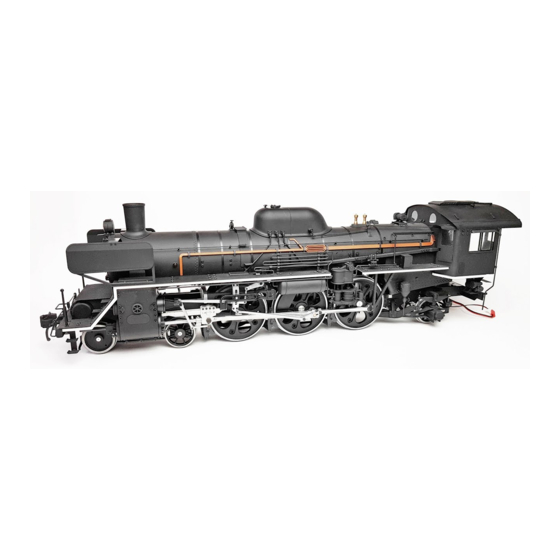
- Page 1 Build the Steam Locomotive Pack 02...
- Page 2 Editorial and design by Continuo Creative, 39-41 North Road, London N7 9DP. Published in the UK by De Agostini UK Ltd, Battersea Studios 2, 82 Silverthorne Road, London SW8 3HE. Published in the USA by De Agostini Publishing USA, Inc., 915 Broadway, Suite 609, New York, NY 10010.
- Page 3 Step by step: Stage The front deck Where your parts fit Front deck Front deck side Your parts The front deck base fits onto the projecting tab at the bottom of the smokebox. Front deck base Tools Front deck upper plate Front left deck side Phillips screwdriver Front right deck side...
- Page 4 Remove the deck base and apply some Once the deck multi-purpose adhesive to the tab. is in its best position, fully tighten the screws into place. You can apply instant adhesive to Before the glue dries, move the ends of the deck to the left and right, the screws to trying to get it as close to the...
- Page 5 Step by step: Stage The feedwater Where your parts fit system Feedwater heater Feedwater heater holder Your parts Narrow Wide The feedwater heater body has a narrow end and a wide end, as indicated above. Glue end B into the wide end of Feedwater heater end B goes in the wide the feedwater heater with multi- end and feedwater heater end A fits into...
- Page 6 Place the two bands Align the holes at the sides of the holder with the of the feedwater corresponding holes in the deck. Tighten a 2 × heater holder over the 2mm screw into the lowest of the three holes on feedwater heater.
- Page 7 Step by step: Stage The release lever Where your parts fit Release lever Front end beam Your parts This picture shows the difference between a release lever A, on the left, and a Place the four release levers onto the release lever release lever B, on the right.
- Page 8 Insert the pins of the lever into the corresponding holes in the front Apply some multi-purpose end beam. Then repeat for the other adhesive to the two pins three levers. on one of the levers. Apply some instant adhesive to the rear of the holes housing the pins of the levers, to make sure they are secured.
- Page 9 Step by step: Stage The inspection lids Where your parts fit Inspection lids Steps Your parts Apply a small amount of multi- purpose adhesive to the projecting parts of inspection lid A. Have two of the steps ready. Inspection lid A Tools Inspection lid B Steps ×...
- Page 10 Place the front deck upper plate (Stage Align the holes 5) onto the front deck. at the rear of the front beam with those in the brackets. Front deck base Front deck upper plate Insert the two hanging brackets into the rectangular holes in the underside of the front deck.
- Page 11 Step by step: Stage The front deck parts Where your parts fit Steps Grab bars Your parts Air hose Fix the steps to the frame with instant adhesive, and remove any excess glue. Insert the triangular projections of the steps into the holes in step frame A, identifiable by the position of the top projection (circled).
- Page 12 Glue the second grab bar into the hole on the right-hand side of the Push the projection in and then align the front deck. holes. Align the projection on the top of steps B with the circled hole in the Glue one of the grab bars Apply instant underside of the deck.
- Page 13 Step by step: Stage The main underframe Where your parts fit The main underframe Your parts Left Right Place the left and right brake supports together to identify them. Left Right ● ❶ Left Right ● ❷ ● ❷ Right brake support Right Main underframe (left) Tools...
- Page 14 Fit the brake supports to the Position the main underframes and underframes with 2 × 3mm screws. the brace as shown in the photo. This is how the brake supports should appear when fitted to the Tighten a 2 × 5mm screw into each of underframes.
- Page 15 Step by step: Stage The main underframe Where your parts fit front Main underframe front Your parts Position the main underframe (Stage 10) as shown, together with the main underframe front, smoke chamber support and truck support. Main underframe front Tools Smoke chamber support 17 screws 2 ×...
- Page 16 Turn the underframe assembly over and place the truck support between the sides, below the smoke chamber support. Tighten a 2 × 4mm screw into each of the four aligned holes in the left underframe. Position the smoke chamber support between the sections Tighten a 2 ×...
- Page 17 Step by step: Stage The cylinder plates Where your parts fit Cylinder plates Cylinder covers Your parts Left Right Rear Do not apply adhesive around this hole Apply multi-purpose adhesive to the rear of one of the cylinder covers. Then place it onto one arm of the cylinder rear plate, as shown, Tighten a 2 ×...
- Page 18 Fit the second cylinder The cylinder front plate is divided cover to the cylinder into two parts. The front faces of rear plate in the the plates are flat. same way as the first. Remove any excess glue from around the Insert the left cylinder front covers before they dry.
Need help?
Do you have a question about the Model Space C57 and is the answer not in the manual?
Questions and answers