Advertisement
Quick Links
Advertisement

Subscribe to Our Youtube Channel
Related Manuals for De Agostini Model Space C57


Summary of Contents for De Agostini Model Space C57
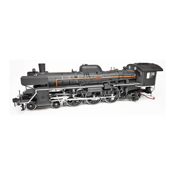
- Page 1 Build the Steam Locomotive Pack 04...
- Page 2 Editorial and design by Continuo Creative, 39-41 North Road, London N7 9DP. Published in the UK by De Agostini UK Ltd, Battersea Studios 2, 82 Silverthorne Road, London SW8 3HE. Published in the USA by De Agostini Publishing USA, Inc.121 E. Calhoun Street, Woodstock, IL 60098.
- Page 3 Step by step: Stage The leaf springs Where your parts fit Leaf springs Your parts First wheels Second wheels Third wheels Right Flat surface on the outside Tools Leaf springs × 6 Left Links (medium) × 8 Links (long) × 2 Phillips screwdriver Links (short) ×...
- Page 4 Insert a 4.5mm bush Nuts into the front hole of the rear equalising bars. Then, take the second wheel leaf spring and place over the Place the links over the ends of Leaf spring underframe, so the the springs and pass a screw bottom of the links up through the aligned holes.
- Page 5 Step by step: Stage The second wheels Where your parts fit Axle box The second driving wheels Your parts Assemble axle boxes A and B as shown Take one of the axle boxes and slide above. Complete the four sets. it up into the gap in the underframe, positioning the frame in the grooves Tools...
- Page 6 Turn the Secure with masking tape underframe over and lower the axle boxes back into place, as shown. Once they are pushed all the way in, you can Place the assembled axle boxes remove the over the axles of the wheels, masking tape.
- Page 7 Step by step: Stage The third wheels Where your parts fit Rear side rod Axle box Third wheels Your parts Assemble the axle boxes over the axle of the third Tools Bushes (large) × 2 wheels and temporarily secure with masking tape. Rod pins ×...
- Page 8 Left side rod Small bush Coupling rod A (Stage 3) Screw Check the connecting rods for any Secure the leaf spring to the flash. Remove any you find with a file. Axle box A long part of the axle box with a 2 ×...
- Page 9 Step by step: Stage The connecting rods Where your parts fit Connecting rod Eccentric rod Your parts Prepare the crossheads Crosshead A Right Left from Stage 16. Arrange them as shown here. Crosshead B Tools Screws (2 × 7mm) × 3 Stepped screws (2 ×...
- Page 10 Place crosshead A onto crosshead B, inserting the pin into the hole in the Place a bush onto connecting rod. the crankpin. Crankpin Insert the piston rod Take crosshead B and slide it Place the hole at over the motion bar, then insert the rear of the left the piston rod into the hole in connecting rod over...
- Page 11 Step by step: Stage The valve gear Where your parts fit The valve gear Your parts Projection Right Eccentric rods Set screws (2 × 3.6mm) (Stage 24) Expansion link central plates (Stage 24) Front Tools Radius rods Radius rods × 2 Hanging links ×...
- Page 12 Right Fit a hanging link at the end of the left radius rod and secure with a 2 × 3.6mm Expansion link outer Front Hanging link set screw (circled). plate (Stage 24) Expansion links Screws Right Set screw Left Hanging Screws Place the outer and inner links...
- Page 13 Step by step: Stage The motion plates Where your parts fit Motion plate Reverse shaft Your parts The reverse shaft has a recess at each end. Recess Tools Left motion plate Right motion plate Phillips screwdriver Reverse shaft Hold the shaft over the Flat-blade screwdriver Reverse link left (Precision screwdriver)
- Page 14 Eccentric rod Insert the piston valve Prepare the two spindle into the hole types of stepped in the piston valve screws shown in tail guide. Then, put the photo. the projection on the Fit the left motion plate to the side Hanging Link expansion link inner of the motion frame, placing the...
- Page 15 Step by step: Stage The leading truck 1 Where your parts fit Leading truck frame Your parts Lay out the parts of the Right leading truck in the orientation shown. Tools Truck frames × 2 Left Front bracket Centre beam Wrench Rear bracket Socket wrench (3mm)
- Page 16 Place the rear bracket at one end of the truck frame assembly. Align the holes in the centre Half-tighten a 2 × 6mm hex head Align the holes in the second truck Place the bracket beam with those in the screw in each of the aligned holes frame with the holes on the other side between the...
- Page 17 Step by step: Stage The leading truck 2 Where your parts fit Links Your parts The four links are all the same size and shape. Tools Leading truck mount Here you can see the Links × 4 difference between the Side stays ×...
- Page 18 Tighten a 2 × 3.8mm stepped screw into the aligned holes. Align a hole at the end of one of the links with the circled hole in the Hold the truck mount over the hole in Align the holes in the leading truck mount.
Need help?
Do you have a question about the Model Space C57 and is the answer not in the manual?
Questions and answers