Advertisement
Quick Links
Advertisement

Related Manuals for De Agostini Model Space C57


Summary of Contents for De Agostini Model Space C57
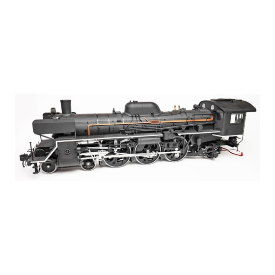
- Page 1 Build the Steam Locomotive Pack 05...
- Page 2 Editorial and design by Continuo Creative, 39-41 North Road, London N7 9DP. Published in the UK by De Agostini UK Ltd, Battersea Studios 2, 82 Silverthorne Road, London SW8 3HE. Published in the USA by De Agostini Publishing USA, Inc.,121 E. Calhoun Street, Woodstock, IL 60098.
- Page 3 Step by step: Stage The leading truck 3 Where your parts fit Equalisers Your parts Pass the threaded part of the link through the hole in the leaf spring, and tighten a nut onto it. Tools Equaliser (outer) × 2 Equaliser (inner) ×...
- Page 4 Inner Larger hole without thread Outer Threaded Place the equalisers on either side of the leaf spring. Tighten a hex head screw through the Make a second set. aligned holes of the outer equaliser, the links The holes in the outer and Place one of the leaf springs between an and the inner equaliser.
- Page 5 Step by step: Stage The leading truck 4 Where your parts fit Wheels Your parts As well as the two leading wheels from this stage, you will also need the leading truck, as well as the side stays, washers, Side stays centre pin and 2 ×...
- Page 6 2 × 4mm screws Place the leading Tighten a 2 × Side stay truck upside- 4mm screw down and lower (Stage 28) the first leading into each of wheels into the the holes. U-shaped area just behind the guard irons. Fit another side stay to the other side of the Fit the second truck with four more 2 ×...
- Page 7 Step by step: Stage The headlamp Where your parts fit Smokebox door handle Headlamp Your parts Position the handle so that there is a 1mm gap between it and the door. Tools Insert the handle into the two holes on the Headlamp smokebox door.
- Page 8 Insert the post at the bottom of the headlamp into the hole at the top of the smokebox (circled). Epoxy adhesive Apply a small amount of epoxy adhesive to the base of the headlamp Prepare the LED cable by removing (circled, above).
- Page 9 Step by step: Stage The smokebox Where your parts fit Smokebox door handle Handrail door lock Your parts Locate the two ridges on either side of Apply some epoxy adhesive to the space the inside of the smokebox door (circled). between the ridges.
- Page 10 Insert the end of the smokebox handle into the hole in the lever. Epoxy adhesive Adjust the position of the Turn the lever lock to match the one Pass the end of the handle into Apply some epoxy adhesive to onto the handle shown above.
- Page 11 Step by step: Stage The boiler 1 Where your parts fit Boiler bottom Your parts Place the boiler joints in front of you, as shown. Identify the outer and inner sides. Outside Inside Hold a boiler joint up against the lower boiler half, aligning the circled holes of both parts.
- Page 12 Secure the boiler joint to the lower boiler half with seven 2 × 3mm screws. These seven holes should still be visible. Complete Fix the second boiler joint to the other side of the lower boiler half with seven 2 × 3mm screws. The lower boiler half should now look like this.
- Page 13 Step by step: Stage The boiler 2 Where your parts fit Boiler top Safety valve Your parts Insert a handrail bracket into Locate the six holes on the left and right one of the holes. of the boiler upper half. Prepare six handrail brackets and six nuts.
- Page 14 Prepare two handrail brackets which fit into the two circled holes in the smokebox, and two nuts which go with the brackets. Align the holes of the handrail brackets before the adhesive dries. Epoxy adhesive Apply some synthetic rubber adhesive to the Fit another two Apply epoxy adhesive to the underside of threaded part of the...
- Page 15 Place the boiler joint Hole into the front of the boiler, aligning the holes at the sides. Tighten a 2 × 3mm screw into the two circled holes. Pass the end of the headlamp Apply synthetic rubber cable through the hole in the top of the superheater.
- Page 16 Step by step: Stage The boiler 3 Where your parts fit Boiler upper rear Your parts Front Higher at the rear Higher at the front Tools Boiler (tapered section) Safety valve cover Safety valve base Phillips screwdriver Safety valves × 2 Screws (2 ×...
- Page 17 Place the safety Place the valve cover over valve base on the top of the base, resting the inside of the on the boiler. boiler section, aligning the circled holes. Screw the two safety valves into the holes in the cover and base. Fully tighten the two screws.
- Page 18 Step by step: Stage The firebox 1 Where your parts fit Control valve lever Firebox (left) Your parts Align the holes of the tapered section of the boiler and the control valve lever. Tools Fusible plugs × 4 Control valve lever Handrail brackets ×...
- Page 19 Repeat this process for the remaining three plugs. The four holes are the locations for the The two circled holes in the firebox Apply a drop of synthetic rubber fusible plugs. Apply synthetic rubber half are the locations for the handrail adhesive to the end of the bracket, adhesive around the hole on the right on brackets.
Need help?
Do you have a question about the Model Space C57 and is the answer not in the manual?
Questions and answers