Table of Contents
Advertisement
Quick Links
Advertisement
Table of Contents

Related Manuals for 3M ScaleGard HP


Summary of Contents for 3M ScaleGard HP
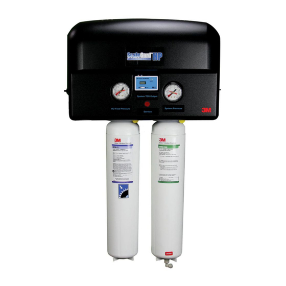
- Page 1 Water Filtration Products ™ Installation and Operation Instructions for ScaleGard HP Reverse Osmosis System (Original Instructions) Installer: Please leave this manual with owner/operator. Owner/Operator: Please retain for operation and future instructions.
-
Page 2: Table Of Contents
Table of Contents Safety Information ........................................3 Caution Statements ........................................4 Parts List ..........................................5 Feedwater Requirements ......................................6 Other Requirements ........................................6 Equipment Set-Up and Installation ....................................7 System Start-Up ........................................10 Routine Maintenance ......................................15, 16 Troubleshooting Guide ......................................17 Product Replacement Parts ...................................... 18 Limited Warranty ...................................... -
Page 3: Safety Information
• DO NOT put this system into service before the RO tank is fl ushed as specifi ed in the installation instructions. Wear eye and face protection during installation. • To request an MSDS relating to this product call 203-238-8965 or visit the web at http://solutions.3m.com). For emergencies, call 800-364-3577 or 651- 737-6501 (24 hours). -
Page 4: Caution Statements
NOTICE NOTICE To reduce the risk associated with property damage due to water leakage or fl ooding: • Read and follow Use Instructions before installation and use of this system. • Change the disposable fi lter cartridge at the recommended interval; the disposable pre-fi lter cartridge and post-fi lter cartridge MUST be replaced every 24 months or sooner. -
Page 5: Parts List
The following parts comprise the ScaleGard HP Reverse Osmosis System. Please unpack the contents from the product box and check to verify that all of the parts listed below are included. Should any parts be missing, please contact 3M Purifi cation Inc. at 1-866-990-9785. Description... -
Page 6: Feedwater Requirements
IMPORTANT NOTES IMPORTANT NOTES ™ • Be sure to confi rm that the feedwater falls within the limits shown below. If unsure of the feedwater quality, check with your 3M Water Filtration Products distributor. Inlet water pressure ......30-125 psi (207-862 kPa) Feed TDS .......... -
Page 7: Equipment Set-Up And Installation
An additional 10" will be needed on both sides of the ScaleGard HP system to allow for the future installation of the SGHP Pre-EXP or the SGHP RO-EXP manifolds. 3. The pressure tank should be installed within 15 ft (4.6 m) of the ScaleGard HP reverse osmosis base unit and 0.5” or larger tubing diameter is required to complete installation. - Page 8 Wall Mounting the ScaleGard HP Base Unit (Mounting Template included with unit) 1. Draw a level line on the wall where the bracket is to be mounted. Hold bracket key holes on level line and mark locations for screws. 2. Install mounting screws (not included) into each of the initial key holes as shown in fi gure 2. Be sure to leave 1/8” to 1/4” (0.3 to 0.6 cm) space between the bottom of the screw head and the wall so that the bracket can be hung.
- Page 9 Plumbing Connections 1. Install feed water line to marked “Inlet” 1/2” NPT inlet connection. 2. Install RO water line from marked “Tank Outlet” to pressure tank (Sold Separately). Assemble and install pressure tank fi ttings per instructions provided with tank. 3.
-
Page 10: System Start-Up
System Start Up Required (Sold Separately) 1. Open unit inlet shutoff valve (See Figure 1, page 7) Approximate Part Number Pressure Volume Time to Fill 2. Turn ON the feedwater supply by plugging system into electrical outlet. 5598407 10 gallons (38 liters) 0.3 hours 3. - Page 11 Blending Valve Adjustment Instructions: IMPORTANT NOTES: • Typical TDS (Total Dissolved Solids) values for coffee are 80-200 ppm (parts per million) and occasionally lower for espresso, depending upon taste preference. Typical TDS valves for steam and combi ovens are less than 50ppm. •...
- Page 12 Figure 6 — Unit Flow Chart Reset Button OUTPUT (FRONT) MODULE LEVER NUT BLUE Pressure Switch 1/3 HP 1/3 HP 60psi on - 40 psi off 1 phase 1 phase BROWN Pump Motor Reset Button WIRE Flow Switch .07gpm off TERMINAL BLOCK (BOTTOM) (BOTTOM)
- Page 13 ScaleGard™ HP PLC (Programable Logic Controller) Program Version 9.8 Sequence of Operation Plug unit in, both the Power and Run LED’s are Green A. If Tank Switch is > 60 psi (414 kPa, 4.14 bar) for 110-120VAC systems or 70 psi (483 kPa, 4.83 bar) for 220-240VAC systems, the unit is off on full tank Unit will cycle on when tank switch senses <...
- Page 14 4. Remove the prefi lter cartridge from the left cartridge head on the manifold. (See diagram) 5. Install bypass plug (3M part # 6217402) into the left hand cartridge head on the manifold. (Note: Operating pressure can't be set/adjusted with used pre-fi lter cartridges) 6.
-
Page 15: Routine Maintenance
Contact a plumbing professional if you are uncertain how to check your water pressure. IMPORTANT NOTE: The RO membrane cartridges have green labels and will only fi t into the head on the right side of the manifold (head has a green 3M label). Shut-Off procedure: RO membrane cartridge will need to be changed at least every twenty four (24) months. - Page 16 Routine Maintenance Cartridge Change-out Instructions (Pre-Filter and RO Membrane Cartridge) RO Membrane Cartridge (green label) Replacement Cont.: 4. Remove sanitary cap from new RO membrane cartridge. Ensure o-rings are seated into their grooves and lubricate with water. Remove plug from new RO membrane cartridge. Install with a quarter turn to the right until RO membrane cartridge comes to a complete stop. NOTE: RO membrane cartridges are keyed to fi t in proper location only.
-
Page 17: Troubleshooting Guide
Troubleshooting Guide Technical Support - 1-866-990-9785 Problem Possible Cause Solution Notes Undersized tank for store demand Install additional storage tank capacity Contact Dealer Install RO add-on head and cartridge RO production is to low for store Contact Dealer Upgrade from HFRO 500 to HFRO 700 demand Cartridge Unit Runs Low or Out of Water... -
Page 18: Product Replacement Parts
Replacement Parts Part Number Description 96-410501 Pressure Reducer/Regulator (Contact Dealer) 60-9052 Inlet ball valve (Contact Dealer) 22-518801 Pre-programmed PLC for 5629101 and 6239301 (Contact Dealer) 25-212401 Relay Output Module for 5629101 and 6239301 22-518802 Pre-programmed PLC for 6239302, 629303, 6239304 (Contact Dealer) 22-115401 Relay Output Module for 6239302, 6239303, and 6239304 8500557... - Page 19 Notes...
- Page 20 Many factors beyond 3M Purifi cation Inc.'s (3M’s) control and uniquely within user’s knowledge and control can affect the use and performance of a 3M product in a particular application. User is solely responsible for evaluating the 3M product and determining whether it is fi t for a particular purpose and suitable for user’s method of application.
Need help?
Do you have a question about the ScaleGard HP and is the answer not in the manual?
Questions and answers