Advertisement
Quick Links
DO
GUIDE
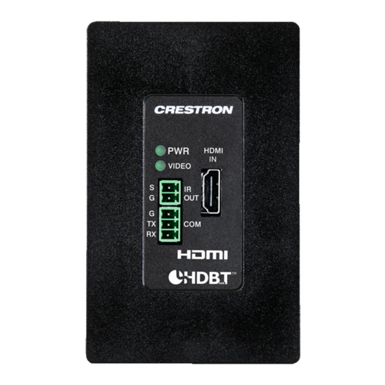
DM-TX-4K-100-C-1G
Wall Plate 4K DigitalMedia 8G+
DO
Make Connections to the Rear Panel
Make connections to the rear panel of the Crestron
unit into an electrical box. If the unit is to be mounted under a table or onto a flat surface or rack
rail, make connections to the rear panel after the unit is mounted. (For mounting instructions,
refer to the "DO Install the Device" section in this guide.)
Make connections to the rear panel as follows:
DM OUT: Connect to the DM 8G+
®
input of a DigitalMedia™ switcher, DigitalMedia 8G+
receiver, or other DigitalMedia device or to an HDBaseT
NOTE:
The DM OUT port is a PoDM (Power over DM) and HDBaseT
PD (Powered Device) port. To receive PoDM or HDBaseT PoE, the DM-TX-4K-100-C-1G requires
a connection to a DigitalMedia switcher or other equipment that has a PoDM or HDBaseT PoE
PSE (Power Sourcing Equipment) port. Any wiring that is connected to a PoDM or HDBaseT PoE
PSE port is for intrabuilding use only and should not be connected to a line that runs outside of
the building in which the PSE is located.
24VDC 0.75A: Connect to the included power pack using the included 2-pin interface
connector.
NOTE:
Connection to the power pack is not required when PoDM or HDBaseT PoE is used to
power the device.
G: Connect to earth ground (building steel).
Refer to illustrations and for sample rear panel connections.
Connection to DigitalMedia Switcher Using PoDM
(External Power Pack Not Required)
Ground
DM-MD8X8
Transmitter 100
®
DM-TX-4K-100-C-1G before mounting the
®
device.
®
®
PoE (Power over Ethernet)
Connection to DigitalMedia Receiver
(External Power Pack Required)
Ground
DM
IN
RES
ET
I OUT
0 -
C
UP
HDM
1 0
SET
- 4
K -
ER
M C
RO
LL
D M
- R
NT
CO
RO
OM
24
V
A MAX
GND
COM
DM
0.75
RX
TX
RTS
DB
T
TM
CTS
A SE
S
1
IR
G
S
2
G
LAN
DM-RMC-4K-100-C
DO
Check the Box
QTY PRODUCT
1
Bracket (for Interface Module)
2
Connector, 2-Pin
1
Connector, 3-Pin
1
Power Pack, 24 Vdc 0.75 A, 100-240 Vac
2
Screw, 6-32 x 3/4", Truss Head, Combo
2
Screw, 6-32 x 1/4", Pan Head, SEMS
DO
Install the Device
The DM-TX-4K-100-C-1G can be mounted into an electrical box, under a table, or onto a flat
surface or rack rail.
®
Mounting into an Electrical Box
The DM-TX-4K-100-C-1G mounts into a 1-gang electrical box (not included). A minimum
mounting depth of 3-1/2 inches (89 mm) is required.
Using a Phillips head screwdriver, attach the DM-TX-4K-100-C-1G to the electrical box using
the two included 6-32 x 3/4-inch truss combo head screws. Then, attach a decorator-style
faceplate (not included) to the front panel of the DM-TX-4K-100-C-1G using two screws (not
included). Refer to illustration .
Mounting into an Electrical Box
Power
pack
COLOR
PART NUM.
Black
2016054
2003574
2003575
2045866
2009211
Black
2007218
Advertisement

Subscribe to Our Youtube Channel
Related Manuals for Crestron DM-TX-4K-100-C-1G


Summary of Contents for Crestron DM-TX-4K-100-C-1G
- Page 1 Install the Device refer to the “DO Install the Device” section in this guide.) The DM-TX-4K-100-C-1G can be mounted into an electrical box, under a table, or onto a flat Make connections to the rear panel as follows: surface or rack rail.
- Page 2 NOTE: This equipment has been tested and found to comply with the limits for a Class B digital device, pursuant to part 15 of the Other trademarks, registered trademarks, and trade names may be used in this document to refer to either the entities claiming the marks and names or their products. Crestron disclaims any FCC Rules.
Need help?
Do you have a question about the DM-TX-4K-100-C-1G and is the answer not in the manual?
Questions and answers