National Instruments UMI-7774 User Manual
Universal motion interface
Hide thumbs
Also See for UMI-7774:
- User manual and specifications (42 pages) ,
- User manual and specifications (42 pages) ,
- User manual and specifications (42 pages)

Related Manuals for National Instruments UMI-7774


Summary of Contents for National Instruments UMI-7774
- Page 1 Motion Control National Instruments Universal Motion Interface (UMI)-7774/7772 User Manual National Instruments UMI-7774/7772 User Manual June 2004 Edition Part Number 373359B-01...
- Page 2 Thailand 662 992 7519, United Kingdom 44 0 1635 523545 For further support information, refer to the Technical Support and Professional Services appendix. To comment on the documentation, send email to techpubs@ni.com. © 2003–2004 National Instruments Corporation. All rights reserved.
- Page 3 The reader should consult National Instruments if errors are suspected. In no event shall National Instruments be liable for any damages arising out of or related to this document or the information contained in it.
- Page 4 These classes are known as Class A (for use in industrial-commercial locations only) or Class B (for use in residential or commercial locations). All National Instruments (NI) products are FCC Class A products. Depending on where it is operated, this Class A product could be subject to restrictions in the FCC rules. (In Canada, the Department of Communications (DOC), of Industry Canada, regulates wireless interference in much the same way.) Digital...
-
Page 5: Table Of Contents
Mounting the UMI-7774/7772..................2-6 Mounting the UMI-7774/7772 on a DIN Rail..........2-7 Mounting the UMI-7774/7772 on a Panel............2-9 Mounting the UMI-7774/7772 in a Standard 19 in. Rack.......2-12 Chapter 3 Connecting the UMI-7774/7772 to Drives and Other Devices Connecting the UMI-7774/7772 to National Instruments Motion Controllers .....3-2 Connecting the UMI-7774/7772 to Optional General-Purpose Digital I/O Devices..3-3... - Page 6 Analog Input ....................3-24 Trigger/Breakpoint..................3-25 Trigger ....................3-25 Breakpoint ..................3-26 General-Purpose Digital I/O ................3-27 Connecting Switches to UMI-7774/7772 Sinking Inputs....3-29 Inductive Loads Connected to UMI-7774/7772 ....... 3-30 Servo Drive Modes......................3-31 National Instruments Motion Advisors ................. 3-32 Appendix A...
-
Page 7: About This Manual
About This Manual The National Instruments Universal Motion Interface (UMI)-7774/7772 User Manual provides information about the UMI-7774/7772 functionality and includes instructions for getting started, specifications, connection requirements, and safety information. Conventions The following conventions appear in this manual: » The » symbol leads you through nested menu items and dialog box options to a final action. -
Page 8: Introduction
For consistency, the remainder of this user manual refers only to drives. All references to drives also apply to amplifiers. You can use the UMI-7774/7772 with a wide variety of drives designed for many types of motors or actuators and power ranges. This flexibility allows you to use the UMI-7774/7772 in systems where you must use a third-party drive. -
Page 9: Features
Chapter 1 Introduction Features The UMI-7774/7772 is designed for use with National Instruments 73xx series motion controllers. This section provides an overview of the UMI-7774/7772 functionality. T I O I N S V is IN H 2 4 V IB IT ±... - Page 10 Capability to interface with low-cost third-party brushless motor drives that do not provide sinusoidal commutation • Access to eight digital inputs and eight digital outputs • Panel, DIN rail, or rack mountable © National Instruments Corporation National Instruments UMI-7774/7772 User Manual...
-
Page 11: Installation
However, if you use the same power supply for both connections, there will be no isolation between the I/O and the main power. Note For a current list of the third-party drives that the UMI-7774/7772 supports, visit the National Instruments Motion Control Web site at ni.com/motion ©... -
Page 12: Optional Equipment
Chapter 2 Installation Optional Equipment National Instruments offers a variety of products for use with the UMI-7774/7772, including the following: • Mounting accessories. Refer to the Mounting the UMI-7774/7772 section for information about specific equipment for each available mounting package. -
Page 13: Safety Information
Safety Information Caution The following paragraphs contain important safety information you must follow when installing and operating the UMI-7774/7772 and all devices connecting to the UMI-7774/7772. Do not operate the device in a manner not specified in the documentation. Misuse of the device can result in a hazard. You can compromise the safety protection built into the device. - Page 14 Working voltage is the highest rms value of an AC or DC voltage that can occur across any particular insulation. MAINS is defined as a hazardous live electrical supply system that powers equipment. Suitably rated measuring circuits may be connected to the MAINS for measuring purposes. National Instruments UMI-7774/7772 User Manual ni.com...
-
Page 15: Unpacking The Umi-7774/7772
The UMI-7774/7772 ships in an antistatic package to prevent electrostatic discharge from damaging device components. After removing the UMI-7774/7772 from the package, inspect it for loose components or any other signs of damage. Contact National Instruments if the device appears damaged in any way. -
Page 16: Mounting The Umi-7774/7772
Installation Mounting the UMI-7774/7772 You can mount the UMI-7774/7772 on a 35 mm DIN rail, on a panel, or in a standard 19 in. rack. The following sections include instructions for all three mounting methods. Before using any of these mounting methods, record the serial number from the back of the UMI-7774/7772. -
Page 17: Mounting The Umi-7774/7772 On A Din Rail
778710-01) from National Instruments. Complete the following steps to mount the UMI-7774/7772 on a DIN rail. To prevent damage to the UMI-7774/7772, do not use screws longer than .25 in. Caution to fasten the DIN rail clip to the UMI-7774/7772. - Page 18 Insert one edge of the DIN rail into the deeper opening of the DIN rail clip, as shown in Figure 2-4. Press down firmly on the UMI-7774/7772 to compress the spring until the clip locks in place on the DIN rail.
-
Page 19: Mounting The Umi-7774/7772 On A Panel
Chapter 2 Installation Mounting the UMI-7774/7772 on a Panel You must use a panel-mount kit to mount the UMI-7774/7772 on a panel. You can order the appropriate kit (part number 778709-01 or 778711-01) from National Instruments. Complete the following steps to install the panel-mount kit. - Page 20 T I O I N S Figure 2-6. Fastening the Vertical Panel-Mount Brackets to the UMI-7774/7772 Attach the panel-mount accessory to a panel using 8-32 or M4 screws. The external dimensions for the UMI-7772 are the same as the dimensions for the Note UMI-7774, shown in Figure 2-7 and Figure 2-8.
- Page 21 LIMIT LED FAULT ENABLE LIMIT LED FAULT ENABLE LIMIT LED FAULT ENABLE LIMIT LED FAULT ENABLE Figure 2-7. UMI-7774/7772 Front View with Horizontal Panel Mount Dimensions FAULT HOME FAULT HOME FAULT HOME FAULT HOME LIMIT LED FAULT ENABLE LIMIT LED...
-
Page 22: Mounting The Umi-7774/7772 In A Standard 19 In. Rack
Installation Mounting the UMI-7774/7772 in a Standard 19 in. Rack To mount the UMI-7774/7772 in an EIA-standard 19 in. rack, you must use the rack-mount kit (part number 778712-01) from National Instruments. Complete the following steps to install the rack-mount kit. -
Page 23: Connecting The Umi-7774/7772 To Drives And Other Devices
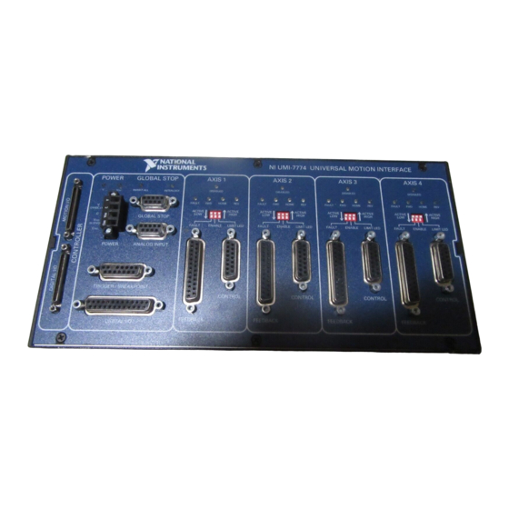
This chapter describes how to wire National Instruments motion controllers, third-party drives, sensors, and field I/O to the UMI-7774/7772. This chapter also describes the polarity settings and LED indicators on the UMI-7774/7772. Figure 3-1 and Figure 3-2 show the UMI-7774 and UMI-7772 front panels. FAULT HOME FAULT... -
Page 24: Connecting The Umi-7774/7772 To National Instruments Motion Controllers
Connecting the UMI-7774/7772 to National Instruments Motion Controllers To connect the UMI-7774/7772 to a National Instruments motion controller, connect one end of the SHC68-C68-S cable to the 68-pin motion I/O connector on the motion controller and the other end to the 68-pin motion I/O connector on the UMI-7774/7772. -
Page 25: Connecting The Umi-7774/7772 To Optional General-Purpose Digital I/O Devices
5 SHC68-C68-S Cable 3 UMI-7774/7772 Motion I/O Connector 6 NI 73xx Digital I/O Connector Figure 3-3. UMI-7774/7772 Connected to an NI 73xx Series Motion Controller Connecting the UMI-7774/7772 to Optional General-Purpose Digital I/O Devices To access 16 (eight inputs and eight outputs) of the 32 digital I/O signals... -
Page 26: Voltage Considerations For The Umi-7774/7772
Chapter 3 Connecting the UMI-7774/7772 to Drives and Other Devices Voltage Considerations for the UMI-7774/7772 Do not connect the UMI-7774/7772 isolated power to a source greater than 30 V. Caution Doing so may cause damage to UMI-7774/7772 components. To cause current to flow through the input, the voltage applied to the following types of inputs should be greater than 3.5 V and less than 30 V. - Page 27 5–30 VDC supply to the V terminal and the negative lead to the terminal on the UMI-7774/7772. If you do not use the isolation feature on the UMI-7774/7772, you must connect the V terminal to the V terminal and the C terminal to the C terminal.
-
Page 28: Connector Descriptions
The UMI-7774/7772 requires a 24 VDC power supply to operate. The UMI-7774/7772 has a 4-position terminal block for wiring 24 VDC power and 5 to 30 VDC isolated power to the UMI-7774/7772. The isolated power is used in the optical isolation output circuitry for the drive enable outputs and digital output signals. - Page 29 HIGH LIMIT LED FAULT ENABLE CONTROL FEEDBACK Figure 3-5. UMI-7774/7772 Per Axis Control and Feedback Connectors, LED Status Indicators, and Polarity Switches (Axis 1 Shown as Example) Table 3-2. Per Axis Control Connector Pin Assignment Signal Optically Isolated Analog Output...
-
Page 30: Analog Output
Fault – Iso Common Analog Output The UMI-7774/7772 analog output signals are used as command outputs to servo drives or as general-purpose voltage outputs. To help keep digital noise separate from the analog outputs, Pin 9 provides a separate analog output ground connection. -
Page 31: Fault
Chapter 3 Connecting the UMI-7774/7772 to Drives and Other Devices Fault The Fault signal is an optically isolated digital input. If the Fault input signal is asserted, the DISABLED LED is lit and the Enable output signal is deactivated. You can wire the Fault input to either a current sourcing or sinking output from a drive or other device. - Page 32 Chapter 3 Connecting the UMI-7774/7772 to Drives and Other Devices Viso Fault + Current Limiter (Sinking) Output Device Fault – Ciso V– UMI-7774/7772 Figure 3-7. Example of Wiring a Sinking Output Device to the Fault Input Viso High-Side Switch Fault + Current Limiter Fault –...
-
Page 33: Enable Output
Chapter 3 Connecting the UMI-7774/7772 to Drives and Other Devices Viso Fault + Current Limiter Fault – Low-Side Switch Ciso UMI-7774/7772 Figure 3-9. Example of Wiring a Low-Side Switch to the Fault Input Enable Output The Enable output signal is an optically isolated digital output used to enable the drive for the axis. - Page 34 Chapter 3 Connecting the UMI-7774/7772 to Drives and Other Devices You must configure the National Instruments motion controller Inhibit Out signals Note as active-low for proper operation of the inhibit logic on the UMI-7774/7772. Controller UMI-7774/7772 Axis 1 Axis Enable...
-
Page 35: Fault Input And Disabled Status Indicators
Refer to Figure 3-5 for the locations of these LEDs. Sinusoidal Commutation Configuration The control connectors for axes 1 and 2 of the UMI-7774/7772 have additional analog output signal connections to accommodate brushless servo drives that do not provide onboard sinusoidal commutation. These signal connections are shown in Table 3-3 and Table 3-4. - Page 36 Sensors Motor Figure 3-12. Sinusoidal Commutation Wiring Diagram You must connect the digital I/O cable from your National Instruments motion controller to the UMI-7774/7772 to promote connectivity with the Hall effect sensors. The Hall effect sensor connections are shown on Pins 5, 6, and 7 in Table 3-5.
- Page 37 Note These drives can be more expensive, but each drive requires only one analog output signal. When you set up the UMI-7774/7772 for sinusoidal commutation, you connect the axis 1 feedback connector to the set of Hall effect sensors for one brushless motor and the axis 2 feedback connector to the set of Hall effect sensors for another brushless motor.
-
Page 38: Feedback Connector For Each Axis
Iso Common Feedback Connector for Each Axis Each axis connected to the UMI-7774/7772 has a 25-pin D-SUB feedback connector to which you can wire incremental encoders, limits, and home sensors. The feedback connectors for axes 1 and 2 have additional connections for Hall effect sensors for brushless motors. - Page 39 Chapter 3 Connecting the UMI-7774/7772 to Drives and Other Devices Table 3-5. Per Axis Feedback Connector Pin Assignment Signal Optically Isolated Encoder Phase A Encoder Phase B Encoder Index +5 V (Output) Hall Sensor A Hall Sensor B Hall Sensor C...
-
Page 40: Encoder
Chapter 3 Connecting the UMI-7774/7772 to Drives and Other Devices Encoder The UMI-7774/7772 works only with encoders that have differential line or complementary driver outputs. Refer to Figure 3-13 for an illustration of the encoder input interface circuit. The UMI-7774/7772 supports differential inputs for Phase A, Phase B, and Index signals. - Page 41 When connecting the encoder wiring to the UMI-7774/7772, use shielded wire of at least 24 AWG. National Instruments recommends you use cables with twisted pairs and an overall shield for improved noise immunity and signal integrity. Figure 3-15 shows twisted pairs in a shielded cable.
-
Page 42: Limit And Home Inputs
The home sensor or switch can be located at any reference position within the range of travel. The limits and home inputs are sinking inputs on the UMI-7774/7772 and are optically isolated. A sinking input is an input terminal that can sink current by providing a path to a supply common or ground. -
Page 43: Limit And Home Status Indicators
Configuring the limit and home status LEDs on the UMI-7774/7772 does not Note configure the limit and home inputs themselves as active-high or active-low. You must configure the limit and home inputs separately on the National Instruments motion controller using MAX or NI-Motion driver software. -
Page 44: Hall Effect Sensors For Sinusoidal Commutation Configuration
Connecting the UMI-7774/7772 to Drives and Other Devices Hall Effect Sensors for Sinusoidal Commutation Configuration The feedback connectors for axes 1 and 2 of the UMI-7774/7772 have additional signal connections for digital Hall effect sensors to accommodate brushless servo drives without onboard sinusoidal commutation. -
Page 45: Global Stop
Figure 3-17. UMI-7774/7772 Pin Locations for Global Stop, Analog Input, Trigger/Breakpoint, and Digital I/O Connectors Global Stop The UMI-7774/7772 has a single 9-pin D-SUB connector for global stop wiring. This connector includes the Inhibit All input and the Shutdown input signals. Both signals are optically isolated sinking inputs. -
Page 46: Shutdown
Analog Input The UMI-7774/7772 has a single 9-pin D-SUB connector that provides access to the four analog input channels on the motion controller. The analog inputs are pass-through signals on the UMI-7774/7772. Refer to... -
Page 47: Trigger/Breakpoint
None of the analog inputs are optically isolated. Note Trigger/Breakpoint The UMI-7774/7772 has a single 15-pin D-SUB connector you can use for trigger input and breakpoint output wiring. This connector provides access to four trigger inputs and four breakpoint outputs. -
Page 48: Breakpoint
Iso Common Refer to Figure 3-1 to locate the Trigger/Breakpoint connector on the UMI-7774/7772. Refer to Figure 3-17 for the pin locations of the trigger/breakpoint connector and to Table 3-8 for the corresponding signals for each pin. Refer to the appropriate National Instruments motion controller documentation for information about trigger inputs and breakpoint outputs. -
Page 49: General-Purpose Digital I/O
The 8 bits from the first port on the motion controller (Port 1: bits 0–7) become sinking inputs on the UMI-7774/7772, and the 8 bits from the second port of the motion controller (Port 2: bits 0–7) become sourcing outputs on the UMI-7774/7772. - Page 50 Chapter 3 Connecting the UMI-7774/7772 to Drives and Other Devices Table 3-9. Digital I/O Connector Pin Assignment (Continued) Signal Optically Isolated Digital Input 5 Digital Input 7 Iso Common Iso Common Iso Common Digital Output 1 Digital Output 3 Digital Output 5...
-
Page 51: Connecting Switches To Umi-7774/7772 Sinking Inputs
Connecting Switches to UMI-7774/7772 Sinking Inputs Figure 3-19 shows an example of connecting a physical switch to a general purpose Digital Input on the UMI-7774/7772. You can make the same type of connection for the following UMI-7774/7772 sinking inputs: •... -
Page 52: Inductive Loads Connected To Umi-7774/7772
Digital Input Ciso UMI-7774/7772 Figure 3-19. UMI-7774-7772 Optically Isolated Sinking Input Interface Circuit and Connection to High-Side Switch Inductive Loads Connected to UMI-7774/7772 When an inductive load, such as a relay or solenoid, is connected to an output, a large counter-electromotive force may occur at switching time because of the energy stored in the inductive load. -
Page 53: Servo Drive Modes
Figure 3-20. Use of External Flyback Diode for Inductive Loads Servo Drive Modes National Instruments recommends that when you use the UMI-7774/7772 with a servo motor drive, you use the torque (current) mode option on the drive instead of the velocity mode to simplify the system setup and tuning. -
Page 54: National Instruments Motion Advisors
Chapter 3 Connecting the UMI-7774/7772 to Drives and Other Devices National Instruments Motion Advisors You can use National Instruments Motion Advisors to find National Instruments products and third-party drives that will work for your application. Visit to access the National ni.com/motion/advisors... -
Page 55: Appendix A Specifications
Specifications The following specifications apply only to the UMI-7774/7772. Consider the specifications for the National Instruments motion controller you are using to obtain a complete system specification for the UMI-7774/7772. Refer to the controller specifications to determine overall system specifications. - Page 56 Output voltage range ......5 to 30 V Output current ..........60 mA, maximum 24 V ..........150 mA, maximum 30 V ..........160 mA, maximum Maximum pulse rate .......10 kHz Minimum pulse generated ......100 µs National Instruments UMI-7774/7772 User Manual ni.com...
- Page 57 Short circuit and overload protection..Yes Step/Direction/Breakpoint Outputs Compatibility ......... Signal pass-through Analog Inputs Compatibility ......... Signal pass-through Analog Outputs Compatibility ......... Signal pass-through Host Bus Voltage Interlock Voltage ........... 4.2 VDC © National Instruments Corporation National Instruments UMI-7774/7772 User Manual...
- Page 58 Input voltage range .........24 V ± 10%, .20 Amps power source........5 to 30 VDC, 1.75 Amps Environmental Conditions The UMI-7774/7772 is intended for indoor use only. Operating temperature ......0 to 55 °C Storage temperature ........–30 to 80 °C Humidity ..........10 to 90% RH, noncondensing Maximum altitude........2,000 m...
- Page 59 Specifications Safety The UMI-7774/7772 is designed to meet the requirements of the following standards of safety: • IEC 61010-1, EN 61010-1 • UL 3111-1, UL 61010B-1 • CAN/CSA C22.2 No. 1010.1 For UL and other safety certifications, refer to the product label or to Note ni.com...
- Page 60 Technical Support and Professional Services Visit the following sections of the National Instruments Web site at for technical support and professional services: ni.com • Support—Online technical support resources at ni.com/support include the following: – Self-Help Resources—For immediate answers and solutions,...
- Page 61 You also can visit the Worldwide Offices section of to access the branch ni.com/niglobal office Web sites, which provide up-to-date contact information, support phone numbers, email addresses, and current events. National Instruments UMI-7774/7772 User Manual ni.com...
- Page 62 3-21 documentation conventions used in manual, vii NI resources, B-1 related documentation, vii Inhibit All input, 3-24 drivers (NI resources), B-1 installation, 2-1 instrument drivers (NI resources), B-1 © National Instruments Corporation National Instruments UMI-7774/7772 User Manual...
- Page 63 2-2 overview, 1-1 unpacking, 2-5 using twisted pair cable, 2-2 panel-mounting, 2-9 pass-through signaling, 3-20 power input terminal block, 3-6 Web resources, B-1 power status indicators, 3-6 programming examples (NI resources), B-1 National Instruments UMI-7774/7772 User Manual ni.com...
Need help?
Do you have a question about the UMI-7774 and is the answer not in the manual?
Questions and answers