National Instruments UMI-7774 User Manual And Specifications
Hide thumbs
Also See for UMI-7774:
- User manual (63 pages) ,
- User manual and specifications (42 pages) ,
- User manual and specifications (42 pages)
Table of Contents
Advertisement
Quick Links
Advertisement
Table of Contents

Subscribe to Our Youtube Channel
Related Manuals for National Instruments UMI-7774


Summary of Contents for National Instruments UMI-7774
- Page 1 Artisan Technology Group is your source for quality new and certified-used/pre-owned equipment SERVICE CENTER REPAIRS WE BUY USED EQUIPMENT • FAST SHIPPING AND DELIVERY Experienced engineers and technicians on staff Sell your excess, underutilized, and idle used equipment at our full-service, in-house repair center We also offer credit for buy-backs and trade-ins •...
-
Page 2: Table Of Contents
Mounting the UMI-7774/72......................... 9 Mounting the UMI-7774/72 on a DIN Rail ................. 10 Mounting the UMI-7774/72 on a Panel..................11 Mounting the UMI-7774/72 in a Standard 19 in. Rack ............... 14 Connector Descriptions........................14 Power Input Terminal Block......................14 Connecting Power To the UMI-7774/72 ................15 Power Status Indicators ....................... -
Page 3: Introduction
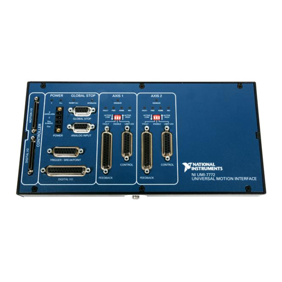
For consistency, the remainder of this user manual refers only to drives. All references to drives also apply to amplifiers. You can use the UMI-7774/72 with a wide variety of drives designed for many types of motors or actuators and power ranges. This flexibility allows you to use the UMI-7774/72 in systems where you must use a third-party drive. - Page 4 Also, the UMI-7774/72 features a host bus monitor power interlock that automatically disables the drive if the host computer is shut down or the motion input/output interface cable is disconnected. Figure 1 shows the UMI-7774.
-
Page 5: Safety Information
Although some signal lines on the UMI-7774/72 have optical isolation to reduce noise effects and ground loops, the UMI-7774/72 does not include safety isolation features. Also, there is no isolation between signals, connectors, or axes on the UMI-7774/72 unless otherwise noted. -
Page 6: Electromagnetic Compatibility Information
, search by model number or product line, ni.com/certification and click the appropriate link in the Certification column. © National Instruments Corporation NI UMI-7774/72 User Guide and Specifications Artisan Technology Group - Quality Instrumentation ... Guaranteed | (888) 88-SOURCE | www.artisantg.com... -
Page 7: Related Documentation
• Drive documentation Installation This section describes the required and optional items for getting started with the UMI-7774/72. This section also explains how to unpack, configure, and install the UMI-7774/72. Required Materials The following items are necessary for installing and getting started with the UMI-7774/72: ❑... -
Page 8: Optional Equipment
Unpacking and Installing the UMI-7774/72 The following steps provide a high-level overview for connecting the UMI-7774/72 with NI motion controllers, drives, and other I/O. Refer to Figure 1 for the UMI-7774/72 connector, LED, and switch locations. Note The UMI-7774/72 ships in an antistatic package to prevent electrostatic discharge from damaging device components. - Page 9 Connect the UMI-7774/72 to the NI 73xx motion controller by connecting one end of the SHC68-C68-S cable to the 68-pin motion I/O connector on the motion controller and the other end to the 68-pin motion I/O connector on the UMI-7774/72. Refer to Figure 2 for a connection diagram.
-
Page 10: Noise Considerations
UMI-7774/72. Mounting the UMI-7774/72 You can mount the UMI-7774/72 on a 35 mm DIN rail, on a panel, or in a standard 19 in. rack. The following sections include instructions for all three mounting methods. Before using any of these mounting methods, record the serial number from the back of the UMI-7774/72. -
Page 11: Mounting The Umi-7774/72 On A Din Rail
Figure 5. UMI-7774, Side View with Dimensions Mounting the UMI-7774/72 on a DIN Rail The UMI-7774/72 has one clip for mounting on a standard 35 mm DIN rail. You can order the DIN rail mounting kit (part number 778710-01) from National Instruments. Complete the following steps to mount the UMI-7774/72 on a DIN rail. -
Page 12: Mounting The Umi-7774/72 On A Panel
Insert one edge of the DIN rail into the deeper opening of the DIN rail clip, as shown in Figure 7. Press down firmly on the UMI-7774/72 to compress the spring until the clip locks in place on the DIN rail. - Page 13 Fasten the two brackets of the panel-mount kit to the back of the UMI-7774/72 using a number 2 Phillips screwdriver and the 8-32 .25 in. countersink screws shipped with the panel-mount kit. These screws have a nylon coating to prevent them from loosening.
- Page 14 LIMIT LED FAULT ENABLE LIMIT LED FAULT ENABLE LIMIT LED FAULT ENABLE LIMIT LED FAULT ENABLE Figure 10. UMI-7774/72 Front View with Horizontal Panel Mount Dimensions 6 in. FAULT HOME FAULT HOME FAULT HOME FAULT HOME (152 mm) LIMIT LED...
-
Page 15: Mounting The Umi-7774/72 In A Standard 19 In. Rack
The UMI-7774/72 requires a 24 VDC power supply to operate. The UMI-7774/72 has a 4-position terminal block for wiring 24 VDC power and 5 to 30 VDC isolated power to the UMI-7774/72. The isolated power is used in the optical isolation output circuitry for the drive enable outputs and digital output signals. -
Page 16: Connecting Power To The Umi-7774/72
UMI-7774/72 as an output power source for external devices. Refer to Figure 1 to locate the power input terminal block on the UMI-7774/72. Figure 13 shows the 4-position power connector. Table 1 shows the power connector terminal block pinout. -
Page 17: Power Status Indicators
LEDs. Control Connector for Each Axis Each axis connected to the UMI-7774/72 has a 15-pin D-SUB control connector to which you wire drive command and drive enable signals. Figure 14 shows the pin locations of the control connector for each axis. -
Page 18: Analog Output
Step (CW) and Dir (CCW) The UMI-7774/72 Step (CW) and Dir (CCW) signals are used as command outputs to a stepper drive. Some stepper drives require clockwise direction (CW) and counterclockwise direction (CCW) commands rather than Step and Dir commands. -
Page 19: Fault
Current Limiter V– Fault – Ciso UMI-7774/72 Figure 15. Example of Wiring a Sourcing Output Device to the Fault Input NI UMI-7774/72 User Guide and Specifications ni.com Artisan Technology Group - Quality Instrumentation ... Guaranteed | (888) 88-SOURCE | www.artisantg.com... - Page 20 Current Limiter Fault – Ciso UMI-7774/72 Figure 17. Example of Wiring a High-Side Switch to the Fault Input © National Instruments Corporation NI UMI-7774/72 User Guide and Specifications Artisan Technology Group - Quality Instrumentation ... Guaranteed | (888) 88-SOURCE | www.artisantg.com...
-
Page 21: Enable Output
It monitors the +5 V pin from the motion controller to verify that the motion controller is powered on and properly connected to the UMI-7774/72. NI UMI-7774/72 User Guide and Specifications ni.com... - Page 22 You must configure the NI 73xx motion controller Inhibit Out signals as active low for proper operation of the inhibit logic on the UMI-7774/72. This is the default setting for these signals. Figure 19 shows a simplifed connection diagram for the Enable, Fault, and Global Stop signals.
-
Page 23: Feedback Connector For Each Axis
Figure 20. UMI-7774/72 Optically Isolated Digital Output Circuit and Connection to an External Device Feedback Connector for Each Axis Each axis connected to the UMI-7774/72 has a 25-pin D-SUB feedback connector to which you can wire incremental encoders, limits, and home sensors. Figure 14 shows the pin locations of the feedback connector for each axis. - Page 24 Provides 1 A maximum output current, shared between Control connector pin 3, Feedback connector pins 4 and 8, and Trigger/Breakpoint connector pin 3. © National Instruments Corporation NI UMI-7774/72 User Guide and Specifications Artisan Technology Group - Quality Instrumentation ... Guaranteed | (888) 88-SOURCE | www.artisantg.com...
-
Page 25: Encoder
The UMI-7774/72 works only with encoders that have differential line or complementary driver outputs. Refer to Figure 21 for an illustration of the encoder input interface circuit. The UMI-7774/72 supports differential inputs for Phase A, Phase B, and Index signals. -
Page 26: Limit And Home Inputs
When connecting the encoder signals to the UMI-7774/72, use shielded wire of at least 24 AWG. National Instruments recommends you use cables with twisted pairs and an overall shield for improved noise immunity and signal integrity. - Page 27 V– Ciso UMI-7774/72 Figure 24. UMI-7774/72 Optically Isolated Sinking Input Interface Circuit and Connection to Sourcing Output Sensor You can also connect the limit and home inputs to a high-side switch. Figure 25 shows an example of wiring the limit or home input to a high-side switch.
-
Page 28: Limit And Home Status Indicators
Limit and Home Status Indicators The UMI-7774/72 has yellow status LEDs for the forward limit, reverse limit, and home input signals. Refer to Figure 14 for the location of these LEDs. You can configure the limit and home status LEDs as active low or active high using the switch for the axis labeled LIMIT LED. -
Page 29: Global Stop
The analog inputs are pass-through signals on the UMI-7774/72. Refer to Figure 1 to help you locate the analog input connector on the UMI-7774/72. Figure 26 shows the pin locations for the Analog Input connector. Table 7 shows the corresponding signals for each pin. -
Page 30: Trigger/Breakpoint
All of the trigger inputs on the UMI-7774/72 are sinking inputs and are optically isolated. You can wire the trigger input to a sourcing output device such as a PNP sensor, as shown in Figure 24, or to a high-side switch as shown in Figure 28. -
Page 31: General-Purpose Digital I/O
The 8 bits from the first port on the motion controller (Port 1: bits 0–7) become sinking inputs on the UMI-7774/72, and the 8 bits from the second port of the motion controller (Port 2: bits 0–7) become sourcing outputs on the UMI-7774/72. Refer to Figure 26 for the pin locations of the Digital I/O NI UMI-7774/72 User Guide and Specifications ni.com... - Page 32 Table 9 for the corresponding signals for each pin. Refer to Figures 24 through 29 for information on how to wire the digital inputs and outputs on the UMI-7774/72. Table 9. Digital I/O Connector Pin Assignment Signal...
- Page 33 Output Load Ciso UMI-7774/72 Figure 27. UMI-7774/72 Optically Isolated Sourcing Digital Output Interface Circuit and Connection to an External Load NI UMI-7774/72 User Guide and Specifications ni.com Artisan Technology Group - Quality Instrumentation ... Guaranteed | (888) 88-SOURCE | www.artisantg.com...
-
Page 34: Connecting Switches To Umi-7774/72 Sinking Inputs
Use this protection method if you connect any of the Enable outputs or general-purpose digital outputs on the UMI-7774/72 to an inductive load. Refer to Figure 29 for an illustration of the interface circuit for a general-purpose digital output that is connected to an external device with a flyback diode. -
Page 35: Servo Drive Modes
When you use torque mode, you can set all of the control gains with the National Instruments motion controller software. Using torque mode on the drive also reduces noise and enables you to achieve high position repeatability in the motion system. -
Page 36: Encoder Interface
............150 mA, maximum 30 V ............160 mA, maximum Maximum pulse rate ..........10 kHz Minimum pulse generated ........100 µs © National Instruments Corporation NI UMI-7774/72 User Guide and Specifications Artisan Technology Group - Quality Instrumentation ... Guaranteed | (888) 88-SOURCE | www.artisantg.com... -
Page 37: General Purpose Digital Outputs
Storage temperature ..........–30 to 80 °C Humidity ..............10 to 90% RH, noncondensing Pollution Degree (IEC 60664) .......2 Maximum altitude..........2,000 m Indoor use only. NI UMI-7774/72 User Guide and Specifications ni.com Artisan Technology Group - Quality Instrumentation ... Guaranteed | (888) 88-SOURCE | www.artisantg.com... -
Page 38: Shock And Vibration
This product meets the essential requirements of applicable European Directives, as follows: • 2006/95/EC; Low-Voltage Directive (safety) • 2004/108/EC; Electromagnetic Compatibility Directive (EMC) © National Instruments Corporation NI UMI-7774/72 User Guide and Specifications Artisan Technology Group - Quality Instrumentation ... Guaranteed | (888) 88-SOURCE | www.artisantg.com... -
Page 39: Online Product Certification
At the end of the product life cycle, all products must be sent to a WEEE recycling center. For more information about WEEE recycling centers, National Instruments WEEE initiatives, and compliance with WEEE Directive 2002/96/EC on Waste and Electronic Equipment, visit ni.com/environment/weee... -
Page 40: Umi-7774/72 Pinouts
UMI-7774/72 Pinouts The Figure 30 shows the pin assignments for all UMI-7774/72 connectors. Refer to Figure 1 for the UMI-7774/72 connector locations. Shutdown Inhibit All (OUT) If you are not using the isolation feature, you must connect V to V and C to C Refer to the User Guide for more information. -
Page 41: Worldwide Support And Services
National Instruments corporate headquarters is located at 11500 North Mopac Expressway, Austin, Texas, 78759-3504. National Instruments also has offices located around the world to help address your support needs. For telephone support in the United States, create your service request at ni.com/... - Page 42 Artisan Technology Group is your source for quality new and certified-used/pre-owned equipment SERVICE CENTER REPAIRS WE BUY USED EQUIPMENT • FAST SHIPPING AND DELIVERY Experienced engineers and technicians on staff Sell your excess, underutilized, and idle used equipment at our full-service, in-house repair center We also offer credit for buy-backs and trade-ins •...
Need help?
Do you have a question about the UMI-7774 and is the answer not in the manual?
Questions and answers