Advertisement
Quick Links
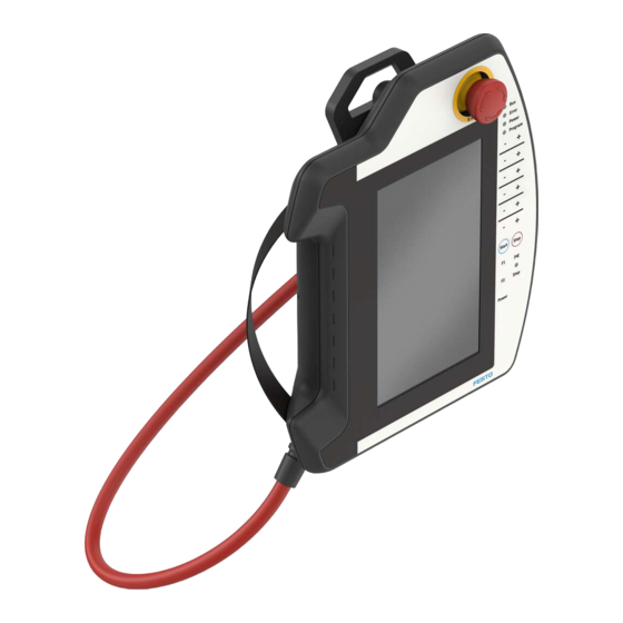
CDSA-D3-RV
Operator unit
Brief instruction | Safety manual
8135651
202008
[8135653]
Translation of the original instructions
© 2020 all rights reserved to Festo SE & Co. KG
Pilz
®
, TORX
®
are registered trademarks of the respective trademark owners in cer
tain countries.
1
About this document
1.1
Purpose of the document
This document describes the handheld terminal CDSAD3RV.
This document is the safetyrelevant part of the operating instructions in accord
ance with the Machinery Directive 2006/42/EG.
Complete operating instructions are available for the product.
1.2
Applicable documents
All available documents for the product è www.festo.com/sp.
Document
Interface housing CAMIC
Declaration of conformity
Tab. 1 Applicable documents
1.3
Product labelling
•
Observe the specifications on the product.
The product labelling enables identification of the product and shows the follow
ing information, for example:
Product labelling (sample)
1
Type code
2
Part number
3
Production date (month/year)
4
Technical data (voltage/current)
5
Ambient temperature
6
Manufacturer
7
Manufacturer's address
8
Country of origin
9
Plant number
10
UL inspection mark
11
KC identification
12
Serial number
13
CE conformity marking
Tab. 2 Product labelling (sample)
Festo SE & Co. KG
Ruiter Straße 82
73734 Esslingen
Germany
+49 711 3470
www.festo.com
8135651
Table of contents
Assembly instructions
Manufacturer's declaration of conformity with 2006/42
/ EC and other directives
1.4
Specified standards
EN ISO 13850:2015
EN ISO 10218:2011
EN 602041:2006+A1:2009+AC:2010
EN 6094758:2007
EN 611312:2007
Tab. 3 Specified standards
1.4.1
Quantitative safety specifications for the emergency stop device and
the 3-position enabling switch
Festo provides a B
value è 11.1 Handheld terminal CDSAD3RV.
10D
Other values are not provided by Festo, e.g. SIL, PL and category. Reason: Festo
supplies the switching element, but does not evaluate the element. The customer
must connect and monitor the emergency stop device and the 3position enabling
switch for the application. The customer receives SIL or category with PL by the
method in which the emergency stop function and the enabling control function
are implemented in the machine.
1.4.2
Abbreviations
Abbrevi-
English term
ation
B
–
10D
MTTF
Mean time to Failure Dan
D
gerous
DC
Diagnostic Coverage
PL
Performance Level
PFH
Probability of Failure per
D
Hour Dangerous
SIL
Safety Integrity Level
Tab. 4 Abbreviations
2
Safety
2.1
Safety instructions
–
Only use the product in original status without unauthorised modifications.
Only the conversions and modifications described in this and the additional
documents are permitted.
–
Only use the product if it is in perfect technical condition.
–
Observe further applicable documents.
–
Observe labelling on the product.
–
Installation, commissioning, maintenance and disassembly should only be
conducted by qualified personnel.
–
Observe the mounting and connection specifications.
–
Take into consideration the ambient conditions at the location of use.
–
Comply with specified critical limits.
–
The cable must not be crushed by objects.
–
Do not route the cable over sharp edges.
–
Select the cable length to ensure sufficient access to the danger zone.
–
When not in use, place and attach the product to the existing wall bracket.
–
The product must be stored in such a way that control elements cannot be
actuated or damaged.
–
Foreign matter or liquids must not penetrate the product.
–
Check the product if damage is suspected.
2.2
Intended use
The intended use of the handheld terminal CDSAD3RV extends from monitoring
and parameterisation to the operation of machines, e.g. Festo handling systems.
The devices for the safety engineering are an emergency stop device and a 3posi
tion enabling switch.
The handheld terminal must not be used for temporary connection.
Remove nonfunctional or disconnected devices from the area of the user in order
to avoid accidental actuation of the nonfunctional emergency stop device.
All safety engineering equipment is designed with 2 circuits and permits imple
mentation of category 4 PL e in accordance with EN ISO 138491, taking into
account the actuation cycles with reference to the B
devices.
2.3
Foreseeable misuse
The following areas of application are expressly excluded for the handheld termin
al CDSAD3RV:
–
Use in potentially explosive areas or areas where there is a risk of fire
–
Use in mining
–
Outdoor use
2.4
Training of qualified personnel
This document contains information for people with the following prerequisites:
Description
Number of cycles until dangerous failure of 10% of the
components (per channel)
Mean time to dangerous failure (per channel)
Diagnostic coverage
Discrete level that specifies the ability of safetyrelated
devices to execute a safety function under foreseeable
conditions.
Average probability of a dangerous failure per hour
Safety integrity level
values of the safety
10D
Advertisement

Related Manuals for Festo CDSA-D3-RV


Summary of Contents for Festo CDSA-D3-RV
- Page 1 Festo provides a B value è 11.1 Handheld terminal CDSAD3RV. www.festo.com Other values are not provided by Festo, e.g. SIL, PL and category. Reason: Festo supplies the switching element, but does not evaluate the element. The customer Brief instruction | Safety manual must connect and monitor the emergency stop device and the 3position enabling...
- Page 2 5 Strain relief and antikink device for Service connecting cable (supplied with 2 Touch pen holder connecting cable) Contact your regional Festo contact person if you have technical questions 3 3position enabling switch è www.festo.com. 6 USB port 4 Connection shaft cover...
- Page 3 Mode of operation The 3position enabling switch can be in one of three different switch positions: Switch setting Function 3-position Switch contact enabling switch Neutral position not actuated Off (opened) Enabling is actuated On (closed) Panic is pressed Off (opened) Tab.
- Page 4 Mount cable Foreseeable misuse of the 3-position enabling switch Unauthorised fixing of the 3position enabling switch in the enabling position with mechanical aids must be regarded as foreseeable misuse, which must be preven ted. The following measures, which cause the machine to come to rest in manual over ride, are recommended: •...
- Page 5 Housing made of ABS fault and application to Festo for analysis. Flammability UL94V0 – Check with your regional Festo contact person to clarify the conditions for the Fallproof suitability 1.5 (on industrial floor), then at least return shipment. degree of protection IP54 Disposal Tab.
- Page 6 Dimensions, weight Depth (incl. handle and emergency stop [mm] device) Weight Approx. 950 Tab. 14 Dimensions, weight 11.1.1 Accessories The product may only be operated with the accessories named in this chapter. 11.1.1.1 Wall bracket CAFM-D4-W The powdercoated black wall bracket is used for stationary operation or for stor ing the handheld terminal CDSAD3RV.
Need help?
Do you have a question about the CDSA-D3-RV and is the answer not in the manual?
Questions and answers