Table of Contents
Advertisement
Quick Links
Advertisement
Table of Contents

Related Manuals for Festo CDSA-D3-RV


Summary of Contents for Festo CDSA-D3-RV
- Page 1 CDSA-D3-RV Operator unit Operating instructions 8127392 8127392 2020-08 [8127394]...
- Page 2 Translation of the original instructions ® ® ® AZUL , Pilz , TORX are registered trademarks of the respective trademark owners in certain coun- tries. Festo — CDSA-D3-RV — 2020-08...
-
Page 3: Table Of Contents
Transport and storage....................22 Mounting and installation................... 22 Mounting the connecting cable..................23 Cable installation in the connection shaft..............26 Power supply........................ 27 Connecting the handheld terminal CDSA-D3-RV to a Festo controller......27 Configuration....................... 27 Diagnosis data......................28 Display.......................... 29 Licences.........................31 Network.........................31... - Page 4 13.2.1.4 CAMF-B-M25-G4 jumper plug................. 50 Appendix: Safety of machinery..................50 14.1 Risk assessment......................51 14.2 Principles for the integration of the handheld terminal CDSA-D3-RV......51 14.3 Technical documentation....................52 14.4 State of the art.......................52 14.5 Presumption of conformity with harmonised standards..........53 14.6...
- Page 5 Technical systems as sources of interference............59 15.1.4 Technical systems as interference sinks..............59 15.1.5 Coupling paths......................60 15.2 EMC measures for the handheld terminal CDSA-D3-RV..........60 15.2.1 Screen connections....................60 15.2.2 Shielding within the control cabinet................62 Appendix: Resistance to chemicals................62...
-
Page 6: About This Document
About this document About this document Purpose of the document This document describes the handheld terminal CDSA-D3-RV. Applicable documents All available documents for the product è www.festo.com/sp. Product labelling • Observe the specifications on the product. The product labelling enables identification of the product and shows the following information, for example:... -
Page 7: Specified Standards
Festo provides a B value è 13.2 Handheld terminal CDSA-D3-RV. Other values are not provided by Festo, e.g. SIL, PL and category. Reason: Festo supplies the switch- ing element, but does not evaluate the element. The customer must connect and monitor the emer- gency stop device and the 3-position enabling switch for the application. -
Page 8: Abbreviations
The product must be stored in such a way that control elements cannot be actuated or damaged. – Foreign matter or liquids must not penetrate the product. – Check the product if damage is suspected. – Never place the product on unstable surfaces. – Never place the product near heat sources. Festo — CDSA-D3-RV — 2020-08... -
Page 9: Intended Use
The connection shaft must only be opened when the supply voltage is switched off. Intended use The intended use of the handheld terminal CDSA-D3-RV extends from monitoring and parameterisa- tion to the operation of machines, e.g. Festo handling systems. The devices for the safety engineering are an emergency stop device and a 3-position enabling switch. -
Page 10: Ul/Csa Certification
File number E239998 Considered standards UL 508 CSA C22.2 No. 142 UL mark Tab. 7 UL/CSA certification information Additional Information – Accessories è www.festo.com/catalogue. Service Contact your regional Festo contact person if you have technical questions è www.festo.com. Festo — CDSA-D3-RV — 2020-08... -
Page 11: Product Overview
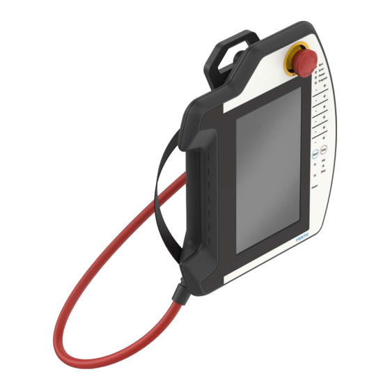
Configuration 5.1.1 Product design The handheld terminal CDSA-D3-RV is a portable operating and display device. The colour display can be used to perform graphical tasks. The touchscreen enables intuitive user guidance. The devices for the safety engineering are an emergency stop device and a 3-position enabling switch. -
Page 12: Display And Operating Components
4 Connection shaft cover Fig. 2 Rear view 5.1.2 Display and operating components Colour LC display The handheld terminal CDSA-D3-RV is equipped with a backlit colour LCD display with 7 "TFT in WSVGA resolution (600 x 1024 pixels). Festo — CDSA-D3-RV — 2020-08... - Page 13 • Do not press product too hard. The handheld terminal CDSA-D3-RV is equipped with a robotics keyboard with tactile feedback. The touch sensitive keyboard has 20 keys and 5 status LEDs. The handheld terminal CDSA-D3-RV is equipped with an analogue-resistive touchscreen. The touch- screen can be operated with one finger, with or without a glove or with a touch pen.
-
Page 14: Connecting Elements
1 Ethernet plug/communication interface 2 Pin header - main plug/supply and control cables Fig. 3 Connection shaft for handheld terminal CDSA-D3-RV Connection The following graphic shows the connection of the control cables (power supply, emergency stop and enabling circuits) and the data cables to the interface housing. -
Page 15: Emergency Stop Device
Product overview Fig. 4 Connection diagram: handheld terminal CDSA-D3-RV on interface housing CAMI-C A Crossover cable is required between the handheld terminal CDSA-D3-RV and the controller for point- to-point operation via the Ethernet interface. 5.1.3.2 Emergency stop device The handheld terminal CDSA-D3-RV has an emergency stop device. The emergency stop device is wired in 2 circuits and the contacts are designed as normally closed contacts. -
Page 16: 3-Position Enabling Switch
5.1.3.3 3-position enabling switch The handheld terminal CDSA-D3-RV has a 3-position enabling switch. An essential feature is the 2-cir- cuit design and the forced opening in accordance with EN 60947-1 and EN 60947-5-8 to the third switch position. - Page 17 Neutral position not actuated Off (opened) Enabling is actuated On (closed) Panic is pressed Off (opened) Tab. 8 Mode of operation of the 3-position enabling switch Normal actuation Fig. 5 Switching path diagram for normal actuation Festo — CDSA-D3-RV — 2020-08...
- Page 18 PilzPNOZ s6.1. The following connection example shows how the 3-position enabling switch of the handheld terminal CDSA-D3-RV achieves an enabling function up to category 4 PL e. The entire machine must be designed for this purpose.
- Page 19 (manual override). The 3-position enabling switch must not be in the enabling position. • The 3-position enabling switch must be released within a specified period and returned to the enabling position. The length of the period must be selected according to the job requirement. Festo — CDSA-D3-RV — 2020-08...
- Page 20 The graphic shows a suggested circuit for achieving the category 4 PL e for the enabling function with a monitoring device. The monitoring device and subsequent components must be included in the cal- culation of the entire safety function "Enable via 3-position enabling switch". Festo — CDSA-D3-RV — 2020-08...
-
Page 21: Ethernet
5.1.3.4 Ethernet The Ethernet interface is available as standard in the handheld terminal CDSA-D3-RV. The Ethernet interface is based on the default 10Base-T specification and is suitable for full-duplex operation. Oper- ation with 100 Mbit (100Base-T specification) is only possible with a suitable connecting cable. -
Page 22: Transport And Storage
1. Remove USB memory stick. 2. Press protective cap firmly down. Transport and storage – Maintain ambient conditions è 13.2 Handheld terminal CDSA-D3-RV. – Use the original packing for transport. Also use the original packaging for onward or return trans- port. -
Page 23: Mounting The Connecting Cable
Check that the cables are not pinched at any point. • Check that all screws are tight. Otherwise, the degree of protection cannot be guaranteed. This chapter describes how the connecting cable is mounted on the handheld terminal CDSA-D3-RV. Available connecting cables è 13.2 Handheld terminal CDSA-D3-RV. Required tool The following tools are required to mount the cables: –... - Page 24 1 TORX screw Fig. 9 Position of the TORX screws 1. Loosen the TORX screws on the cover plate with a size 10 TORX screwdriver. 2. Open cover. Do not damage the cables of the 3-position enabling switch. Festo — CDSA-D3-RV — 2020-08...
- Page 25 Fig. 11 Connecting cable 4. Insert the connecting cable through the passage provided into the handheld terminal CDSA-D3-RV. A grey nut is integrated in this passage for mounting the connecting cable. 5. Fix the grommet with a size 19 spanner (torque: 3 Nm).
-
Page 26: Cable Installation In The Connection Shaft
Information for opening the connection shaft • Place the handheld terminal CDSA-D3-RV with the display facing downwards on a flat, clean and soft base so that the handheld terminal CDSA-D3-RV or its operating elements are not damaged (e.g. ESD mat). -
Page 27: Power Supply
Connecting the handheld terminal CDSA-D3-RV to a Festo controller The handheld terminal CDSA-D3-RV must be connected to the Festo controller with remote target visu- alisation via an Ethernet interface to enable commissioning and series operation. The connection is usually made via an interface housing, an interface box or a connection box in which the signals (Eth- ernet, voltage, safety engineering) are divided. -
Page 28: Diagnosis Data
Configuration The device configuration can only be opened during run-up of the handheld terminal CDSA-D3-RV. If the handheld terminal CDSA-D3-RV is supplied with power, the run-up starts. 1. Start the handheld terminal CDSA-D3-RV. Ä After a short time, the message "Press any key to enter setup" appears for 2 seconds. -
Page 29: Display
Ä A TGZ file is saved in the root directory of the USB stick. 4. Remove USB sticks from the handheld terminal. 5. Send TGZ file to Festo. Display Press the "Display" button to open the display window. Display settings can be made in this window. - Page 30 Touch calibration Use a touch pen for calibration. Press the "Touch Calibration" button to start the touchscreen calibration. The following symbol is used for calibration: Festo — CDSA-D3-RV — 2020-08...
-
Page 31: Licences
IP address can be changed in this window. Fig. 19 Network menu Press the "Back" button to return to the main menu. The following values are preset by default in the delivery status of the handheld terminal CDSA-D3-RV: The device is set to DHCP. Ethernet 0 Press the "Ethernet 0"... -
Page 32: Version Info
To do this, select the corres- ponding segments. Fig. 20 Network settings (Ethernet 0) Identifier Address Address IP address of the handheld terminal CDSA-D3-RV Netmask Associated subnet mask Gateway Standard gateway DHCP Activation of "DHCP"... -
Page 33: Operation
For cyclical write operations (e.g. logging), use the temporary file system in the RAM or a remov- able storage medium The run-up or start-up process of the handheld terminal CDSA-D3-RV after insertion can be monitored on the screen and runs in the following sequence: 1. -
Page 34: Restore Backup, Install Software Or Firmware Update
BSS preparation To prepare the USB stick, the archive (e.g. ZIP file) supplied by Festo must be extracted and the "\boot" directory copied to the root directory of the USB stick. The USB stick must be at least 4 GB, must not be larger than 32 GB and must be formatted with FAT32. - Page 35 – Service USB stick for the BSS application – Backup/update files 1. Plug service USB stick into the handheld terminal CDSA-D3-RV. 2. Restart (disconnect and reconnect power supply). 3. Select menu option "Backup & Restore". 4. Select menu option "Restore".
-
Page 36: Update Software
Ä The "Update" directory and the "update.img" file are created in the root directory. 3. Remove the USB stick from the PC. 4. Plug USB stick into the handheld terminal CDSA-D3-RV while it is disconnected from the power supply. 5. Switch on the handheld terminal (default). -
Page 37: Malfunctions
Send handheld terminal CDSA-D3-RV to Festo. Message "System is up to date" The same software version is on the handheld CDSA-D3-RV and the USB stick. To overwrite the current software on the handheld terminal CDSA-D3-RV with the same version and thus reset all settings, the image file in the root directory of the USB stick can be renamed from "update.img"... -
Page 38: Standards
Low-voltage switching devices - Part 5-8: Control units and switch- ing elements - Three-position enabling switch EN 60947-1:2007 Low-voltage switching devices - Part 1: General specifications EN 60947-5-1:2004 Low-voltage switching devices - Part 5-1: Control units and switch- ing elements - Electromechanical control units Festo — CDSA-D3-RV — 2020-08... - Page 39 The following standards have also been taken into consideration for the American market: Standard Title UL certification for industrial control equipment UL 508 Industrial Control Equipment (NRAQ, NRAQ7) UL certification for robotics applications UL 1740 Industrial Robots and Robotic Equipment E216950 (TETZ2, TETZ8) Tab. 17 Standards Festo — CDSA-D3-RV — 2020-08...
-
Page 40: Regulations
Actuating forces – From switch position 1 to 2 Typically 3 N – From switch position 2 to 3 Typically 17 N Electrical isolation [V AC] 500 to all other networks Tab. 20 3-position enabling switch Festo — CDSA-D3-RV — 2020-08... - Page 41 Vibration resistance (in accordance with IEC 60068-2-6) – With 3.5 mm [Hz] £ < – With 1 g [Hz] £ < Shock resistance (in accordance with [g/ms] 15/11 EN 61131-2) Max. operating altitude (sea level) 2,000 Tab. 22 Ambient conditions Festo — CDSA-D3-RV — 2020-08...
-
Page 42: Accessories
Dimensions, weight Height [mm] Width [mm] Depth (incl. handle and emergency stop [mm] device) Weight Approx. 950 Tab. 26 Dimensions, weight 13.2.1 Accessories The product may only be operated with the accessories named in this chapter. Festo — CDSA-D3-RV — 2020-08... -
Page 43: Wall Bracket Cafm-D4-W
Technical data 13.2.1.1 Wall bracket CAFM-D4-W The powder-coated black wall bracket is used for stationary operation or for storing the handheld ter- minal CDSA-D3-RV. 1 Equipment carrier 2 Cable suspension Fig. 23 CAFM-D4-W Festo — CDSA-D3-RV — 2020-08... -
Page 44: Interface Housing Cami-C
Fig. 24 Front and side view of wall bracket CAFM-D4-W, (dimensions in mm) 13.2.1.2 Interface housing CAMI-C The interface housing CAMI-C is used to connect a handheld terminal CDSA-D3-RV to a controller with the connecting cable NEBC-R3Z12G20-KH-5-N-SBS-RSG17-ET-S1. Festo — CDSA-D3-RV — 2020-08... - Page 45 Technical data Views and basic dimensions Fig. 25 Views and basic dimensions (in mm) of the CAMI-C interface housing Festo — CDSA-D3-RV — 2020-08...
- Page 46 This chapter describes the connection of the control cables (power supply, emergency stop and enabling circuits) and the data cables to the interface housing è Fig.4. A crossover cable is required between the handheld terminal CDSA-D3-RV and the controller for point- to-point operation via the Ethernet interface.
- Page 47 Max. interruption duration of the supply [ms] £ voltage (CDSA-D3-RV, corresponding to EN 61131) Power consumption – Without CDSA-D3-RV None – With CDSA-D3-RV Tab. 21 Technical data, general è Starting current (CDSA-D3-RV) Technical data of the handheld terminal è Festo — CDSA-D3-RV — 2020-08...
-
Page 48: Connecting Cable Nebc-R3Z12G20-Kh-Xx-N-Sbs-Rsg17-Et-S1
76.1 Depth [mm] 76.1 Tab. 30 Dimensions, weight 13.2.1.3 Connecting cable NEBC-R3Z12G20-KH-xx-N-SBS-RSG17-ET-S1 The handheld terminal CDSA-D3-RV is available as standard with the following connecting cables: – NEBC-R3Z12G20-KH-5-N-SBS-RSG17-ET-S1: 5 m – NEBC-R3Z12G20-KH-10-N-SBS-RSG17-ET-S1: 10 m – NEBC-R3Z12G20-KH-15-N-SBS-RSG17-ET-S1: 15 m The connecting cable is resistant to water, cleaning agents (alcohols and detergents), oils, greases and lubricants è... - Page 49 2, neg. not used → – not used → – – not used → – TD+ (Ethernet) → – (Ethernet) → – – RD+ (Ethernet) → – (Ethernet) → – – Tab. 31 Pin allocation Festo — CDSA-D3-RV — 2020-08...
-
Page 50: Camf-B-M25-G4 Jumper Plug
Supplementary to this, conformity with the EU directives can be checked by independent, accredited certification bodies and this can be confirmed with an EC type examination certificate. For handheld terminals, in addition to the EMC Directive (EMC Directive 2014/30/EU), the Machinery Directive (MD 2006/42/EC) must also be applied. Festo — CDSA-D3-RV — 2020-08... -
Page 51: Risk Assessment
EN ISO 12100: 2010 "Safety of basic machinery concepts - General principles for design, risk assessment and risk reduction" 14.2 Principles for the integration of the handheld terminal CDSA-D3-RV Appendix I, chapter 1.1.2 of MD 2006/42/EC, MD, describes a clear procedure and sequence for the selection of protective measures: Eliminate or minimise the hazards This is done by the design of the machine. -
Page 52: Technical Documentation
(e.g. the objective of occupational safety, environmental protection, safety of third parties, eco- nomic efficiency: i.e. in general to achieve a generally high level based on the relevant aspects). The state of the art can evolve independently of the standards. Festo — CDSA-D3-RV — 2020-08... -
Page 53: Presumption Of Conformity With Harmonised Standards
However, the total PL required for the safety function is only achieved if the circuitry with the associated circuits has been implemented in accordance with the product description for the respect- ive PL, and the PL of all components contributing to the safety function has been taken into account. Festo — CDSA-D3-RV — 2020-08... -
Page 54: Use Of Handheld Terminals In Special Operating Modes
As can be seen from the following illustration, a machine is constantly in a dangerous state from the point of view of the emergency stop as long as it is not actuated. Festo — CDSA-D3-RV — 2020-08... -
Page 55: Control Elements For Stopping In An Emergency
(see also EN ISO 13850). Changing the ready status of an emergency stop switch is not permissible, as this can lead to incorrect actions and life-threaten- ing loss of time in panic situations. Festo — CDSA-D3-RV — 2020-08... -
Page 56: 14.10 Notes On The 3-Position Enabling Switch
A prerequisite for the application is that the hazard to be controlled is switched off in good time by a 3-position enabling switch before personal injury occurs. This may require additional safety measures, such as a safely reduced speed of drives. Festo — CDSA-D3-RV — 2020-08... -
Page 57: Appendix: Electromagnetic Compatibility
Appendix: Electromagnetic compatibility Directive 2014/30/EU of the European Union requires the member states to harmonise their legisla- tion on electromagnetic compatibility. In the following text, this directive is referred to briefly as EMC Directive. Festo — CDSA-D3-RV — 2020-08... -
Page 58: Electromagnetic Environment - Sources Of Interference, Interference Sinks And Coup
The applicable international product standard IEC 61131-2 (for Europe EN 61131-2) classifies the areas of application into zones. Depending on the applicable zone, higher or lower noise levels can be expected. All Festo control systems and also the products from the handheld CDSA-D3-RV are suitable for use in zone B. -
Page 59: Technical Systems As Sources Of Interference
Power transistors Transistor circuits Minimum Integrated circuits Tab. 33 Immunity to interference and interference sinks Control systems are unthinkable without integrated circuits and would therefore not be sufficiently immune from interference without suitable EMC measures. Festo — CDSA-D3-RV — 2020-08... -
Page 60: Coupling Paths
15.2.1 Screen connections The cable shield of the CDSA-D3-RV cable can be regarded as an extension of the CDSA-D3-RV shield housing (flat module) up to the shield housing of the communication device (e.g. PLC). From this it can be deduced that the shield connections of the cable shield to the device shields make a significant contribution to the immunity to interference of the handheld terminal CDSA-D3-RV . - Page 61 Malfunctions are no longer dissipated and thus have a direct effect on the internal cables. Festo — CDSA-D3-RV — 2020-08...
-
Page 62: Shielding Within The Control Cabinet
Appendix: Resistance to chemicals The following table provides an overview of the basic chemical resistance of the materials used in the handheld terminal CDSA-D3-RV. The list is not exhaustive. Some substances have high creep properties, which means that substances can penetrate the device and components. - Page 63 The resistance of the materials is subdivided into the following classifications in the following table: Classification Description Good resistance Conditional resistance – Poor resistance Tab. 35 Classification of resistance of materials Medium Acetone CAS no.: 000067-64-1 Concentration: – Ammonia CAS no.: 001336-21-6 Concentration: Festo — CDSA-D3-RV — 2020-08...
- Page 64 000064-17-5 Concentration: Hydraulic oil (petroleum- based) CAS no.: – Concentration: – Potash CAS no.: 001310-58-3 Concentration: Linseed oil CAS no: 008001-26-1 Concentration: – Cutting/grinding CAS no.: – Concentration: – Methanol CAS no.: 000067-56-1 Concentration: – Festo — CDSA-D3-RV — 2020-08...
- Page 65 CAS no.: – Concentration: – – Sodium hydrox- CAS no.: 001310-73-2 Concentration: Petroleum ether (white spirit) CAS no.: 008032-32-4 Concentration: – – – Hydrochloric acid CAS no.: 007647-01-0 Concentration: Lubricating grease CAS no.: – Concentration: – Festo — CDSA-D3-RV — 2020-08...
- Page 66 Concentration: Silicone oil CAS no.: – Concentration: – Spirit CAS no.: – Concentration: – – Turpentine CAS no.: – Concentration: – Tab. 36 Basic chemical resistance of the materials used in the handheld terminal CDSA-D3-RV Festo — CDSA-D3-RV — 2020-08...
- Page 68 Festo SE & Co. KG Ruiter Straße 82 73734 Esslingen Germany Phone: +49 711 347-0 Internet: www.festo.com © 2020 all rights reserved to Festo SE & Co. KG...
Need help?
Do you have a question about the CDSA-D3-RV and is the answer not in the manual?
Questions and answers