GEM 566 eSyStep Operating Instructions Manual
Hide thumbs
Also See for 566 eSyStep:
- Operating instructions manual (112 pages) ,
- Operating instructions manual (57 pages) ,
- Operating instructions manual (21 pages)

Related Manuals for GEM 566 eSyStep


Summary of Contents for GEM 566 eSyStep
- Page 1 GEMÜ 566 eSyStep Elektromotorisch betätigtes Regelventil Motorized control valve Betriebsanleitung Operating instructions Weitere Informationen Webcode: GW-566...
- Page 2 Alle Rechte, wie Urheberrechte oder gewerbliche Schutzrechte, werden ausdrücklich vorbehalten. All rights including copyrights or industrial property rights are expressly reserved. Dokument zum künftigen Nachschlagen aufbewahren. Keep the document for future reference. © GEMÜ Gebr. Müller Apparatebau GmbH & Co. KG 19.06.2023 GEMÜ 566 2 / 116...
-
Page 3: Table Of Contents
Begriffsbestimmungen ......... Warnhinweise ..........2 Sicherheitshinweise ..........3 Produktbeschreibung .......... Beschreibung ..........Typenschild ........... 4 GEMÜ CONEXO ............ 5 Bestimmungsgemäße Verwendung ..... 6 Bestelldaten elektromotorisch ......7 Technische Daten ..........8 Elektrischer Anschluss ........9 Abmessungen ............10 Herstellerangaben .......... -
Page 4: Allgemeines
LED-Zustände Symbol Bedeutung Explosionsgefahr! Leuchtet Blinkt Aggressive Chemikalien! 1.4 Begriffsbestimmungen Betriebsmedium Medium, das durch das GEMÜ Produkt fließt. Heiße Anlagenteile! 1.5 Warnhinweise Warnhinweise sind, soweit möglich, nach folgendem Schema gegliedert: SIGNALWORT Art und Quelle der Gefahr Mögliches gefahren- Mögliche Folgen bei Nichtbeachtung. -
Page 5: Sicherheitshinweise
Bei Betrieb: 9. Dokument am Einsatzort verfügbar halten. 10. Sicherheitshinweise beachten. 11. Das Produkt gemäß diesem Dokument bedienen. 12. Das Produkt entsprechend der Leistungsdaten betreiben. 13. Das Produkt ordnungsgemäß instand halten. 14. Wartungsarbeiten bzw. Reparaturen, die nicht in dem Do-... -
Page 6: Beschreibung
Körper mit integrierter Regelmechanik. Es stehen manu- elle, pneumatische und elektromotorische Antriebsarten zur 5 Bestimmungsgemäße Verwendung Verfügung. Das Ventil GEMÜ 566 wurde speziell für die Rege- GEFAHR lung von Kleinmengen entwickelt und erlaubt einen Durchfluss von 63 l/h bis zu 2500 l/h. -
Page 7: Bestelldaten Elektromotorisch
ASTM A 351 CF3M, Feinguss 6 Dichtwerkstoff 7 Spannung/Frequenz 24 V DC 8 Regelmodul Stellungsregler 9 Regelkurve Modifiziert gleichprozentig 10 Kv-Wert 63 l/h 11 Antriebsausführung Antriebsgröße 0 12 CONEXO integrierter RFID-Chip zur elektronischen Identifizierung und Rückver- folgbarkeit www.gemu-group.com 7 / 116 GEMÜ 566 eSyStep... -
Page 8: Technische Daten
Gleichprozentig (Anschluss-Code 1) / Linear (Anschluss-Code 1) Regelkurve Sitz Ø [mm] Kv-Wert DN 8 DN 10 DN 15 G, L G, L G, L 1000 G, L 1600 G, L 2500 G = Gleichprozentig, L = Linear GEMÜ 566 eSyStep 8 / 116 www.gemu-group.com... - Page 9 Stellgeschwindigkeit: max. 3 mm/s Hub: 5 mm Gewicht: DN 8 DN 10 DN 15 DN 15, Code 88 DN 20, Code 88 Gewichte in kg Mechanische Umweltbe- Klasse 4M8 nach EN 60721-3-4:1998 dingungen: www.gemu-group.com 9 / 116 GEMÜ 566 eSyStep...
- Page 10 0/4 - 20 mA; 0 - 10 V (Funktion über IO-Link wählbar) Eingangsart: passiv Eingangswiderstand: 250 Ω Genauigkeit / Linearität: ≤ ±0,3 % v. E. Temperaturdrift: ≤ ±0,1 % / 10°K Auflösung: 12 bit GEMÜ 566 eSyStep 10 / 116 www.gemu-group.com...
- Page 11 PDout 3Byte; PDin 3 Byte; OnRequestData 2 Byte Min. cycle time: 20 ms (eSyStep Stellungsregler, Code S0, S5, S6) Vendor-ID: Device-ID: 1906801 (eSyStep Stellungsregler Code S0, S5, S6), Product-ID: eSyStep Positioner (Code S0, S5, S6) www.gemu-group.com 11 / 116 GEMÜ 566 eSyStep...
-
Page 12: Elektrischer Anschluss
Hinweise: Das Anfahren der Fehlerposition ist nur bei vollständiger Spannungsversorgung möglich. Dieses Verhalten ist keine Sicherheitsstellung. Damit die Funktion bei Spannungsverlust sicherge- stellt ist, muss das Ventil mit einem Notstrommodul GEMÜ 1571 (siehe Zubehör) betrieben werden. Fehlerposition: Geschlossen, Offen oder Hold (Über IO-Link einstellbar). - Page 13 Auf / Zu / Error / Error+Warnung Analogeingang 4 – 20 mA / 0 – 20 mA / 0 – 4 – 20 mA 4 – 20 mA 10 V Analogausgang 4 – 20 mA / 0 – 20 mA / 0 – 4 – 20 mA 4 – 20 mA 10 V www.gemu-group.com 13 / 116 GEMÜ 566 eSyStep...
- Page 14 Nur bei Typ S0, S5, S6 Sollwert (X)+ Analoger Ausgang Werkseinstellung 4-20mA Sollwert (X)- Einstellbar 0-20mA / 0-10V Analoger Eingang 5-poliger M12-Einbaustecker Istwert (Y)+ A-kodiert Werkseinstellung 4-20mA Istwert (Y)- Einstellbar 0-20mA / 0-10V Schalter Verbraucher Signalrichtung Spannungsversorgung GEMÜ 566 eSyStep 14 / 116 www.gemu-group.com...
-
Page 15: Abmessungen
9 Abmessungen 9 Abmessungen 9.1 Einbau- und Antriebsmaße 9.1.1 Ventil mit Gewindemuffe, Code 1 32,0 59,4 81,0 133,5 197,7 282,2 117,7 Maße in mm www.gemu-group.com 15 / 116 GEMÜ 566 eSyStep... - Page 16 9,40 25,0 117,0 33,0 15,0 15,75 25,0 Maße in mm 1) Anschlussart Code 88: Clamp ASME BPE, Baulänge FTF EN 558 Reihe 7 2) Werkstoff Ventilkörper Code C1: ASTM A 351 CF3M, Feinguss GEMÜ 566 eSyStep 16 / 116 www.gemu-group.com...
- Page 17 9 Abmessungen 9.3 Ventilkörperbefestigung 8,10,15,20 Maße in mm www.gemu-group.com 17 / 116 GEMÜ 566 eSyStep...
-
Page 18: Herstellerangaben
„Technische Daten“). Schutzmaßnahmen gegen Überschreitung des maximal ● 4. Lösungsmittel, Chemikalien, Säuren, Kraftstoffe u. ä. nicht zulässigen Drucks durch eventuelle Druckstöße (Wasser- mit GEMÜ Produkten und deren Ersatzteilen in einem schläge) vorsehen. Raum lagern. VORSICHT 10.5 Benötigtes Werkzeug Verwendung als Trittstufe! 1. -
Page 19: Einbaulage
Klammer verbinden. 11.2 Einbaulage 5. Alle Sicherheits- und Schutzeinrichtungen wieder anbrin- gen bzw. in Funktion setzen. GEMÜ empfiehlt eine senkrecht stehende oder hängende Ein- baulage des Antriebs zur Optimierung der Standzeit. 11.3 Einbau mit Gewindemuffe Abb. 1: Gewindemuffe www.gemu-group.com 19 / 116 GEMÜ... -
Page 20: Spezifische Daten Io-Link (Pin 6)
Steckverbinder und die Stromaufnahme des Antriebs sind nicht konform zur IO-Link Spezifikation. 12.1 Betrieb an IO-Link 12.1.1 Betrieb an SPS als 24 V Gerät Der elektromotorische Antrieb GEMÜ eSyStep kann ohne Einschränkungen direkt an einer SPS-Steuerung betrieben werden. Technische Daten des Produkts und der SPS müssen eingehalten werden. Position... - Page 21 2. Pin 4 (CQ) des Masters mit Pin 6 des Produkts verbinden. Im IO-Link Betrieb kann Pin 6 nicht als Ausgangssignal von der SPS-Steuerung ausgewertet werden. Position Benennung eSyStep SPS mit Versorgungsspannung USB IO-Link Master USB-Schnittstelle Netzstecker Laptop www.gemu-group.com 21 / 116 GEMÜ 566 eSyStep...
- Page 22 Spannungsversorgungen verbunden ist. In dem Fall erfolgt der Anschluss des Masters wie bei gleicher Spannungs- versorgung ● Pin 4 (CQ) IO-Link Master mit Pin 6 des Produkts verbinden. Pin 3 (L-) IO-Link Master nicht anschließen. (L-) Position Benennung eSyStep B1 und B2 Versorgungsspannungen USB IO-Link Master GEMÜ 566 eSyStep 22 / 116 www.gemu-group.com...
-
Page 23: Prozessdaten
1 → Process valve in Closed position Operating mode 0 → Normal operation 1 → Initialization mode Valve position analog 8 … 23 Position of the valve in the range 0 … 1000 www.gemu-group.com 23 / 116 GEMÜ 566 eSyStep... -
Page 24: Parameterübersicht
„eSyStep Positio- ner“ 0x13 Product ID Produkt ID auslesen „eSyStep Positio- ner“ 0x15 Serial number Seriennummer aus- „XXXXXXXX/YYYY“ lesen 0x16 Hardware revision Hardware Version „Rev. XX/XX“ auslesen 0x17 Firmware revision Softwareversion „V X.X.X.X.“ auslesen GEMÜ 566 eSyStep 24 / 116 www.gemu-group.com... - Page 25 Logischen Digitalen 0 → Active high outputs Eingang 1 konfigu- 1 → Active low rieren R / W Input 2 Logischen Digitalen 0 → Active high Eingang 2 konfigu- 1 → Active low rieren www.gemu-group.com 25 / 116 GEMÜ 566 eSyStep...
- Page 26 Analog values Poti Analogwert Poten- 0 … 4095 tiometer Supply voltage Analogwert Versor- 0 … 4095 gungsspannung Temperature Analogwert Tempe- 0 … 4095 ratursensor Set value (W) Analogwert Soll- 0 … 4095 wertsignal GEMÜ 566 eSyStep 26 / 116 www.gemu-group.com...
- Page 27 U max Maximalen Span- 100 … 110 nungseingang fest- (10,0 … 11,0 V) legen 0xBA R / W Analog output Direction Wertrichtung Soll- 0 → Rise (steigend) wertausgang ein- 1 → Fall (fallend) stellen www.gemu-group.com 27 / 116 GEMÜ 566 eSyStep...
- Page 28 2 → 0 … 10 V R / W Minimalen Signal- 0 … Max ausgang festlegen (0,0 % … Max) R / W Maximalen Signal- 1000 Min … 1000 ausgang festlegen (Min … 100 %) GEMÜ 566 eSyStep 28 / 116 www.gemu-group.com...
-
Page 29: Parameter
R / W 1 Byte Data storage index Data Storage Cmd UIntegerT8 1 Byte State Property UIntegerT8 4 Byte Data Storage Size UIntegerT32 4 Byte Parameter Checks- UIntegerT32 41 Byte Index List OctetStringT www.gemu-group.com 29 / 116 GEMÜ 566 eSyStep... - Page 30 Parameter Type Values Index Rights 0x0D 8 Byte Profile ArrayT 0x8000 Characteristics 0x8002 0x8003 0x8100 Beschreibung Parameterwerte Indexname Parameter Werte Beschreibung Profile Characteristics 0x8000 Geräte-Identifikation Objekte 0x8002 Prozessdatenabbildung 0x8003 Diagnose 0x8100 Externe Identifikation GEMÜ 566 eSyStep 30 / 116 www.gemu-group.com...
- Page 31 12.4.8 Product name Mit dem Parameter Product name kann der Gerätename im ASCII Format ausgelesen werden. Index Sub- Off- Access Length Indexname Parameter Type Values Index Rights 0x12 18 Byte Product name StringT "eSyStep Positioner" www.gemu-group.com 31 / 116 GEMÜ 566 eSyStep...
- Page 32 Mit dem Parameter Application specific tag kann ein 32 Zeichen langer Text im Gerät gespeichert werden. Zum Beispiel Einbauort, Funktion, Einbau-Datum..Index Sub- Off- Access Length Indexname Parameter Type Values Index Rights 0x18 R / W 32 Byte Application StringT „**************** " specific tag GEMÜ 566 eSyStep 32 / 116 www.gemu-group.com...
- Page 33 Off- Access Length Indexname Parameter Type Values Index Rights 0x25 39 Byte Detailed Device Sta- ArrayT Siehe Kapitel 12.5 Events Beschreibung Parameterwerte Indexname Parameter Werte Beschreibung Detailed Device Status Siehe Kapitel 12.5 Events www.gemu-group.com 33 / 116 GEMÜ 566 eSyStep...
- Page 34 Mit dem Parameter Function digital inputs können Funktionen der digitalen Eingänge konfiguriert werden. Index Sub- Off- Access Length Indexname Parameter Type Default Values Rights 0x4B R / W 3 Bit Function digital in- Input 1 uint:8 puts R / W 3 Bit Input 2 uint:8 GEMÜ 566 eSyStep 34 / 116 www.gemu-group.com...
- Page 35 Bei aktivem Signal arbeitet das Gerät normal. Bei Weg- fall des Signals fährt das Gerät in Sicherheitsstellung. Die Si- cherheitsstellung wird mittels des Parameters Error Action (Index 0x4F (siehe 'Error Action')) definiert. (Init) Eingang kann als Initialisierungs-Eingang verwendet werden. www.gemu-group.com 35 / 116 GEMÜ 566 eSyStep...
- Page 36 (Output Error & Warning) Fehler und Warnungen ausgeben. (Input Init) Ein- / Ausgang als Initialisierungseingang konfigu- rieren. Type in- / output (Push-Pull) Ausgang als Push-Pull konfigurieren. (NPN) Ausgang als NPN konfigurieren. (PNP) Ausgang als PNP konfigurieren. GEMÜ 566 eSyStep 36 / 116 www.gemu-group.com...
- Page 37 (Active low) Eingang 2 invertiert. Input / output 1 (Active high) Ein- / Ausgang nicht invertiert. (Active low) Ein- / Ausgang invertiert. Output 2 (Active high) Ausgang nicht invertiert. (Active low) Ausgang invertiert. www.gemu-group.com 37 / 116 GEMÜ 566 eSyStep...
- Page 38 (Hold) Antrieb bleibt bei einem Fehler in der aktuellen Stel- lung stehen. (Open) Antrieb fährt bei einem Fehler in Stellung AUF. (Close) Antrieb fährt bei einem Fehler in Stellung ZU. Error time 1 … 1000 Zeitverzögerung zwischen Fehlererkennung und Fehlermel- dung festlegen. GEMÜ 566 eSyStep 38 / 116 www.gemu-group.com...
- Page 39 Betriebsmodus für Stellungsregler aktiviert. Betriebsmodus für AUF/ZU-Steuerung aktiviert. IO-Link process data (Disabled) Verwendung von IO-Link Prozessdaten (siehe Ka- pitel 12.2, Seite 23) ist deaktiviert. (Enabled) Verwendung von IO-Link Prozessdaten (siehe Kapi- tel 12.2, Seite 23) ist aktiviert. www.gemu-group.com 39 / 116 GEMÜ 566 eSyStep...
- Page 40 Beschreibung Parameterwerte Indexname Parameter Werte Beschreibung Initialized positions Open 0 … 4092 Analogwert Ventilstellung AUF Close 0 … 4092 Analogwert Ventilstellung ZU Stroke 0 … 4092 Analogwert Hub (Differenz zwischen AUF und ZU). GEMÜ 566 eSyStep 40 / 116 www.gemu-group.com...
- Page 41 Aktuellen Analogwert des Potentiometers auslesen. Supply voltage 0 … 4095 Aktuellen Analogwert der Versorgungsspannung auslesen. Temperature 0 … 4095 Aktuellen Analogwert des Temperatursensors auslesen. Set value (W) 0 … 4095 Aktuellen Analogwert des Sollwerts auslesen. www.gemu-group.com 41 / 116 GEMÜ 566 eSyStep...
- Page 42 Kraft des Ventils einstellen. Werkseitig je nach Ventiltyp vor- eingestellt. Force initialization 1 … 6 Kraft während der Initialisierung einstellen. Werksseitig je nach Ventiltyp voreingestellt. Krafteinstellungen Antriebsgröße Einstellparameter Kraft AG0 und AG1 Kleinste Kraft Maximale Kraft GEMÜ 566 eSyStep 42 / 116 www.gemu-group.com...
- Page 43 Parameter Werte Beschreibung Open / close tight Open tight 800 … 1000 Dichtschließfunktion Ventilposition AUF einstellen. (80,0 … 100,0 %) Close tight 0 … 200 Dichtschließfunktion Ventilposition ZU einstellen. (0 … 20,0 %) www.gemu-group.com 43 / 116 GEMÜ 566 eSyStep...
- Page 44 Min Pos … 1000 Hubbegrenzung des Regelbereichs in Ventilposition AUF ein- (Min Pos … stellen. 100,0 %) Min pos 0 … Max Pos Hubbegrenzung des Regelbereichs in Ventilposition ZU ein- (0,0 % … Max stellen. Pos) GEMÜ 566 eSyStep 44 / 116 www.gemu-group.com...
- Page 45 Wert überschritten, kommt die Meldung „Sollwert zu groß“. U max 100 … 110 Maximalen Wert des Spannungseingangs festlegen. Wird der (10,0 … 11,0 V) eingestellte Wert überschritten, kommt die Meldung „Sollwert zu hoch. www.gemu-group.com 45 / 116 GEMÜ 566 eSyStep...
-
Page 46: Events
Das Event tritt auf, wenn der Ventil ist blockiert (zum Bei- Ventil prüfen 0x8CE0 Motor blockiert ist. spiel Festkörper im Ventil ein- Ist das Ventil in Ordnung, Initia- geklemmt). lisierung durchführen Ventil korrodiert (fest geros- tet). GEMÜ 566 eSyStep 46 / 116 www.gemu-group.com... - Page 47 Ventilstellung gelesen wird, die tilposition. in Richtung „Open“ nie erreicht Fehler beim Tausch einer werden kann. Membrane (Hub des Ventils im falschen Bereich). Antrieb wurde falsch auf Ventil aufgebaut (Hub des Ventils im falschen Bereich). www.gemu-group.com 47 / 116 GEMÜ 566 eSyStep...
-
Page 48: Bedienung
ð LEDs OPEN und CLOSED blinken alternierend. 2. Ventil fährt automatisch in Stellung AUF. 3. Ventil fährt automatisch in Stellung ZU. 4. Initialisierungsmodus wird automatisch beendet. 5. Endlagen sind eingestellt. GEMÜ 566 eSyStep 48 / 116 www.gemu-group.com... -
Page 49: Fehlerbehebung
Betrieb Notstrom, Stellung AUF Betrieb Notstrom, Stellung ZU Betrieb Notstrom, Stellung unbekannt Sollwert zu klein Sollwert zu groß Abbruch IO-Link Kommunikation Wartung nötig, Stellung AUF Wartung nötig, Stellung ZU Wartung nötig, Stellung unbekannt www.gemu-group.com 49 / 116 GEMÜ 566 eSyStep... - Page 50 Befestigungsteile lose Befestigungsteile nachziehen und Ventilkörper undicht Ventilkörper / Antrieb beschädigt Ventilkörper / Antrieb austauschen Ventilkörper des GEMÜ Produkts undicht Ventilkörper des GEMÜ Produkts defekt Ventilkörper des GEMÜ Produkts auf Be- oder korrodiert schädigungen prüfen, ggf. Ventilkörper austauschen Körper des GEMÜ Produkts undicht Unsachgemäße Montage...
-
Page 51: Inspektion Und Wartung
2. Antrieb A auf Regelmechanik 4 setzen. 5. Anlage bzw. Anlagenteil drucklos schalten. 3. Unterlegscheiben 27 über Stiftschrauben 25 legen. 6. GEMÜ Produkte, die immer in derselben Position sind, vier- 4. Befestigungselemente handfest einschrauben und mit ge- mal pro Jahr betätigen. -
Page 52: Regelkegel Austauschen
8. Ventilspindel 21 und Regelkegel 3 mit montierter Trenn- membrane 2 nach unten herausziehen. 7. Sicherungsring 28 entfernen. ð Druckfeder 23 steht unter Spannung. 8. Ventilspindel 21 und Regelkegel 3 mit montierter Trenn- membrane 2 nach unten herausziehen. GEMÜ 566 eSyStep 52 / 116 www.gemu-group.com... -
Page 53: Trennmembrane Austauschen
Teile dabei nicht beschädigen. Danach Teile auf Be- fest montieren. schädigung prüfen. Wenn Teile beschädigt sind, diese 7. Innensechskantschrauben 6 über Kreuz festziehen. dann auswechseln. 15.5.2 Demontage mit Montagewerkzeug 1. Regelkegel demontieren (siehe Kapitel Demontage Regel- kegel). www.gemu-group.com 53 / 116 GEMÜ 566 eSyStep... - Page 54 Teile dabei nicht beschädigen. Danach Teile auf Be- 15.6 Reinigung des Produkts schädigung prüfen. Wenn Teile beschädigt sind, diese dann auswechseln. - Das Produkt mit feuchtem Tuch reinigen. - Das Produkt nicht mit Hochdruckreiniger reinigen. GEMÜ 566 eSyStep 54 / 116 www.gemu-group.com...
-
Page 55: Ausbau Aus Rohrleitung
Entsorgung. 1. Auf Restanhaftungen und Ausgasung von eindiffundierten 1. Das Produkt reinigen. Medien achten. 2. Rücksendeerklärung bei GEMÜ anfordern. 2. Alle Teile entsprechend den Entsorgungsvorschriften / 3. Rücksendeerklärung vollständig ausfüllen. Umweltschutzbedingungen entsorgen. 4. Das Produkt mit ausgefüllter Rücksendeerklärung an GEMÜ... -
Page 56: Konformitätserklärung Nach 2014/68/Eu (Druckgeräterichtlinie)
EN 1983, AD 2000 Hinweis für Produkte mit einer Nennweite ≤ DN 25: Die Produkte werden entwickelt und produziert nach GEMÜ eigenen Verfahrensanweisungen und Qualitätsstandards, welche die Forderungen der ISO 9001 und der ISO 14001 erfüllen. Die Produkte dürfen gemäß Artikel 4, Absatz 3 der Druckgeräterichtlinie 2014/68/EU keine CE-Kennzeichnung tragen. -
Page 57: Konformitätserklärung Nach 2014/30/Eu (Emv-Richtlinie)
20 Konformitätserklärung nach 2014/30/EU (EMV-Richtlinie) 20 Konformitätserklärung nach 2014/30/EU (EMV-Richtlinie) EU-Konformitätserklärung gemäß 2014/30/EU (EMV-Richtlinie) Wir, die Firma GEMÜ Gebr. Müller Apparatebau GmbH & Co. KG Fritz-Müller-Straße 6-8 D-74653 Ingelfingen-Criesbach erklären, dass das unten aufgeführte Produkt die Sicherheitsanforderungen der EMV-Richtlinie 2014/30/EU erfüllt. Benennung des Produktes: GEMÜ... - Page 58 Warning notes ..........2 Safety information ..........3 Product description ..........Description ............. Product label ..........4 GEMÜ CONEXO ............ 5 Correct use ............6 Order data - motorized valve ........ 7 Technical data ............. 8 Electrical connection ........... 9 Dimensions ............
-
Page 59: General Information
Lit (on) Flashing Hot plant components! 1.4 Definition of terms Working medium The medium that flows through the GEMÜ product. 1.5 Warning notes Wherever possible, warning notes are organised according to the following scheme: SIGNAL WORD Type and source of the danger... -
Page 60: Safety Information
Colour Function turer first. Standard Inversed Power/fault green green Operating indica- In cases of uncertainty: tion/ 15. Consult the nearest GEMÜ sales office. communication status Open orange green Process valve in OPEN position Error Error GEMÜ 566 eSyStep 60 / 116... -
Page 61: Description
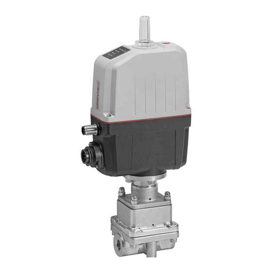
The CONEXO pen helps read out information stored in these 3.3 Description RFID chips. The CONEXO app or CONEXO portal is required to The GEMÜ 566 2/2-way straight seat control valve has a body view this information. with an integrated control mechanism. Manual, pneumatic and motorized actuator types are available. -
Page 62: Order Data - Motorized Valve
24 V DC 8 Control module Positioner 9 Control characteristic Modified equal-percentage 10 Kv value 63 l/h 11 Actuator version Actuator size 0 12 CONEXO Integrated RFID chip for electronic identification and traceability GEMÜ 566 eSyStep 62 / 116 www.gemu-group.com... -
Page 63: Technical Data
Control charac- Seat Ø [mm] Kv value DN 8 DN 10 DN 15 teristic G, L G, L G, L 1000 G, L 1600 G, L 2500 G = equal-percentage, L = linear www.gemu-group.com 63 / 116 GEMÜ 566 eSyStep... - Page 64 DN 10 DN 15 DN 15, code 88 DN 20, code 88 Weights in kg Mechanical environ- Class 4M8 acc. to EN 60721-3-4:1998 mental conditions: Vibration: 5g acc. to IEC 60068-2-6 Test Fc GEMÜ 566 eSyStep 64 / 116 www.gemu-group.com...
- Page 65 Input type: passive Input resistance: 250 Ω Accuracy/linearity: ≤ ±0.3% of full flow Temperature drift: ≤ ±0.1% / 10°K Resolution: 12 bit Reverse battery protec- Yes (up to ± 24 V DC) tion: www.gemu-group.com 65 / 116 GEMÜ 566 eSyStep...
- Page 66 PDout 3Byte; PDin 3 Byte; OnRequestData 2 Byte Min. cycle time: 20 ms (eSyStep positioner, code S0, S5, S6) Vendor-ID: Device-ID: 1906801 (eSyStep positioner, code S0, S5, S6), Product-ID: eSyStep Positioner (code S0, S5, S6) GEMÜ 566 eSyStep 66 / 116 www.gemu-group.com...
-
Page 67: Electrical Connection
Notes: Moving to the error position is only possible with full power supply. This behaviour is not a safety position. The valve must be operated with a GEMÜ 1571 emergency power supply module (see accessories) to ensure the function in case of voltage loss. - Page 68 Digital input 2 Off/Open/Closed/Safe/On/Ini- Safe/On tialization Digital input/output Open/Closed/Error/Error and Error Error warning/Initialization Digital output Open/Closed/Error/Error and Closed Closed warning Analogue input 4–20 mA/0–20 mA/0–10 V 4–20 mA 4–20 mA Analogue output 4–20 mA/0–20 mA/0–10 V 4–20 mA 4–20 mA GEMÜ 566 eSyStep 68 / 116 www.gemu-group.com...
- Page 69 Set value (X)- Adjustable 0-20mA / 0-10V Analogue input 5-pin M12 plug Actual value (Y)+ A-coded Default setting 4 -20mA Actual value (Y)- Adjustable 0-20mA / 0-10V Switch Consumer Signal direction Power supply www.gemu-group.com 69 / 116 GEMÜ 566 eSyStep...
-
Page 70: Dimensions
9 Dimensions 9 Dimensions 9.1 Installation and actuator dimensions 9.1.1 Valve with threaded sockets, code 1 32.0 59.4 81.0 133.5 197.7 282.2 117.7 Dimensions in mm GEMÜ 566 eSyStep 70 / 116 www.gemu-group.com... - Page 71 15.2 15.75 25.0 Dimensions in mm 1) Connection type Code 88: Clamp ASME BPE, face-to-face dimension FTF EN 558 series 7 2) Valve body material Code C1: ASTM A 351 CF3M, investment casting www.gemu-group.com 71 / 116 GEMÜ 566 eSyStep...
- Page 72 9 Dimensions 9.3 Valve body mounting 8,10,15,20 Dimensions in mm GEMÜ 566 eSyStep 72 / 116 www.gemu-group.com...
-
Page 73: Manufacturer's Information
Provide precautionary measures against exceeding the ● 4. Do not store solvents, chemicals, acids, fuels or similar maximum permitted pressures caused by pressure fluids in the same room as GEMÜ products and their spare surges (water hammer). parts. CAUTION 10.5 Tools required Use as step. -
Page 74: Installation Position
11.2 Installation position product and the pipe connection. 4. Connect the gasket between the body of the product and GEMÜ recommend installing the actuator vertically upright or the pipe connection using clamps. vertically down to optimise the service life. 5. Re-attach or reactivate all safety and protective devices. -
Page 75: Specific Data Io-Link (Pin 6)
12.1 Operation on IO-Link 12.1.1 Operation on PLC as a 24 V device The motorized actuator GEMÜ eSyStep can be operated directly in a PLC control unit without limitations. Technical data of the product and of PLC must be complied with. - Page 76 During IO-Link operation, pin 6 cannot be evaluated by the PLC control unit as an output signal. Item Name eSyStep PLC with supply voltage USB IO-Link Master USB interface Mains plug – laptop GEMÜ 566 eSyStep 76 / 116 www.gemu-group.com...
- Page 77 ● Connect pin 4 (CQ) IO-Link master with pin 6 of the product. Do not connect (pin 3) L- IO-Link master. (L-) Item Name eSyStep B1 and B2 Supply voltages USB IO-Link Master www.gemu-group.com 77 / 116 GEMÜ 566 eSyStep...
-
Page 78: Process Data
1 → Process valve in Closed position Operating mode 0 → Normal operation 1 → Initialization mode Valve position analog 8 … 23 Position of the valve in the range 0 … 1000 GEMÜ 566 eSyStep 78 / 116 www.gemu-group.com... -
Page 79: Parameter Overview
Read out product ID "eSyStep Posi- tioner" 0x15 Serial number Read out serial "XXXXXXXX/YYYY" number 0x16 Hardware revision Read out hardware "Rev. XX/XX" version 0x17 Firmware revision Read out software "V X.X.X.X." version www.gemu-group.com 79 / 116 GEMÜ 566 eSyStep... - Page 80 1 → Active low Input / output 1 Configure logical di- 0 → Active high gital input/output 1 → Active low Output 2 Configure logical di- 0 → Active high gital output 1 → Active low GEMÜ 566 eSyStep 80 / 116 www.gemu-group.com...
- Page 81 Operating times Open Operating time 0 to 255 OPEN (0 to 25.5s) Close Operating time 0 to 255 CLOSE (0 to 25.5s) 0x90 Drive sets Force Force, dependent on 1 … 6 valve used www.gemu-group.com 81 / 116 GEMÜ 566 eSyStep...
- Page 82 1 → 4 to 20 mA 2 → 0 to 10 V Min. Determine minimum 0 to Max signal output (0.0% to Max) Determine max- 1000 Min to 1000 imum signal output (Min to 100%) GEMÜ 566 eSyStep 82 / 116 www.gemu-group.com...
-
Page 83: Parameter
Index Rights 0x03 1 byte Data storage index Data Storage Cmd UIntegerT8 1 byte State Property UIntegerT8 4 bytes Data Storage Size UIntegerT32 4 bytes Parameter Check- UIntegerT32 41 bytes Index List OctetStringT www.gemu-group.com 83 / 116 GEMÜ 566 eSyStep... - Page 84 8 bytes Profile ArrayT 0x8000 Characteristics 0x8002 0x8003 0x8100 Description of parameter values Index name Parameter Values Description Profile Characteristics 0x8000 Device identification objects 0x8002 Process data mapping 0x8003 Diagnostics 0x8100 External identification GEMÜ 566 eSyStep 84 / 116 www.gemu-group.com...
- Page 85 The device name can be read out in ASCII format with the Product name parameter. Index Sub- Off- Access Length Index name Parameter Type Values Index Rights 0x12 18 byte Product name StringT "eSyStep Positioner" www.gemu-group.com 85 / 116 GEMÜ 566 eSyStep...
- Page 86 A text with 32 characters can be stored in the device with the Application specific tag parameter. For example, installation location, function, installation date, etc. Index Sub- Off- Access Length Index name Parameter Type Values Index Rights 0x18 32 bytes Application StringT „**************** " specific tag GEMÜ 566 eSyStep 86 / 116 www.gemu-group.com...
- Page 87 Index name Parameter Type Values Index Rights 0x25 39 byte Detailed Device ArrayT See chapter 12.5 Events Status Description of parameter values Index name Parameter Values Description Detailed Device Status See chapter 12.5 Events www.gemu-group.com 87 / 116 GEMÜ 566 eSyStep...
- Page 88 The functions of the digital inputs can be configured with the Function digital inputs parameter. Index Sub- Off- Access Length Index name Parameter Type Default Values Rights 0x4B 3 bits Function digital in- Input 1 uint:8 puts 3 bits Input 2 uint:8 GEMÜ 566 eSyStep 88 / 116 www.gemu-group.com...
- Page 89 If there is no signal, the device moves into the safety position. The safety position is defined by the parameter Error Action (index 0x4F (see "Error Action'"). (Init) Input can be used as an initialization input. www.gemu-group.com 89 / 116 GEMÜ 566 eSyStep...
- Page 90 (Output Error & Warning) Output error and warnings. (Input Init) Configure input/output as initialization input. Type in- / output (Push-Pull) Configure output as Push-Pull. (NPN) Configure output as NPN. (PNP) Configure output as PNP. GEMÜ 566 eSyStep 90 / 116 www.gemu-group.com...
- Page 91 (Active high) Input 2 not inversed. (Active low) Input 2 inversed. Input / output 1 (Active high) Input/output not inversed. (Active low) Input/output inversed. Output 2 (Active high) Output not inversed. (Active low) Output inversed. www.gemu-group.com 91 / 116 GEMÜ 566 eSyStep...
- Page 92 (Open) Actuator moves to the OPEN position in case of an error. (Close) Actuator moves to the CLOSED position in case of an error. Error time 1 … 1000 Determine delay time between error detection and error mes- sage. GEMÜ 566 eSyStep 92 / 116 www.gemu-group.com...
- Page 93 Operating mode for OPEN/CLOSE control activated. IO-Link process data (Disabled) Use of IO-Link process data (see “Process data“, page 78) is deactivated. (Enabled) Use of IO-Link process data (see “Process data“, page 78) is activated. www.gemu-group.com 93 / 116 GEMÜ 566 eSyStep...
- Page 94 Description Initialized positions Open 0 … 4092 Analog value valve position OPEN Close 0 … 4092 Analog value valve position CLOSED Stroke 0 … 4092 Analog value stroke (difference between OPEN and CLOSED). GEMÜ 566 eSyStep 94 / 116 www.gemu-group.com...
- Page 95 Read out current analog value of the supply voltage. Temperature 0 … 4095 Read out current analog value of the temperature sensor. Set value (W) 0 … 4095 Read out current analog value of the set value. www.gemu-group.com 95 / 116 GEMÜ 566 eSyStep...
- Page 96 Force initialization 1 … 6 Set the force during initialization. Preset at the factory de- pending on the valve type. Force settings Actuator size Setting parameter Force AG0 and AG1 Minimum force Maximum force GEMÜ 566 eSyStep 96 / 116 www.gemu-group.com...
- Page 97 Open / close tight Open tight 800 … 1000 Set the sealing function valve position OPEN. (80.0 … 100.0 %) Close tight 0 … 200 Set the sealing function valve position CLOSED. (0 … 20.0 %) www.gemu-group.com 97 / 116 GEMÜ 566 eSyStep...
- Page 98 Set the stroke limiter of the control range in valve position (Min Pos to OPEN. 100.0%) Min pos 0 to Max Pos Set the stroke limiter of the control range in valve position (0.0% to Max CLOSED. Pos) GEMÜ 566 eSyStep 98 / 116 www.gemu-group.com...
- Page 99 "Set value too high" is is- sued. U max 100 to 110 Determine maximum value of the voltage input. If the set (10.0 to 11.0 V) value is exceeded, the message "Set value too high" is is- sued. www.gemu-group.com 99 / 116 GEMÜ 566 eSyStep...
-
Page 100: Events
Motor Unable To Move The event occurs when the Valve is blocked (for example, Check valve 0x8CE0 motor is blocked. solid stuck in valve). Carry out initialization if valve Valve corroded (rusted in is OK place). GEMÜ 566 eSyStep 100 / 116 www.gemu-group.com... - Page 101 "Open" dir- Error when replacing a dia- ection. phragm (stroke of the valve in incorrect area). Actuator has been fitted on the valve incorrectly (stroke of the valve in the incorrect area). www.gemu-group.com 101 / 116 GEMÜ 566 eSyStep...
-
Page 102: Operation
ð OPEN and CLOSED LEDs flash alternately. 2. Valve automatically moves into the OPEN position. 3. Valve automatically moves into the CLOSED position. 4. Initialization mode is automatically ended. 5. The end positions are set. GEMÜ 566 eSyStep 102 / 116 www.gemu-group.com... -
Page 103: Troubleshooting
Emergency power operation, CLOSED position Emergency power operation, position unknown Set value too small Set value too high Abort IO-Link communication Maintenance required, OPEN position Maintenance required, CLOSED position Maintenance required, position unknown www.gemu-group.com 103 / 116 GEMÜ 566 eSyStep... - Page 104 Retighten mounting parts flange and valve body Valve body / actuator damaged Replace valve body/actuator Valve body of the GEMÜ product is leak- Valve body of the GEMÜ product is faulty Check valve body of the GEMÜ product or corroded...
-
Page 105: Inspection And Maintenance
5. Depressurize the plant or plant component. 1. Move the actuator A to the open position. 6. Actuate GEMÜ products which are always in the same po- 2. Place actuator A onto control mechanism 4. sition four times a year. -
Page 106: Replacing The Regulating Cone
7. Remove the circlip 28. ð Compression spring 23 is under tension. 8. Remove the valve spindle 21 and regulating cone 3 with the mounted isolating diaphragm 2 by withdrawing them downwards. GEMÜ 566 eSyStep 106 / 116 www.gemu-group.com... - Page 107 5. Place the control mechanism 4 onto the valve body 1. 6. Mount the washers 7 and hexagon socket screws 6, and tighten the screws by hand. 7. Fully tighten the hexagon socket screws 6 diagonally. www.gemu-group.com 107 / 116 GEMÜ 566 eSyStep...
-
Page 108: Replacing The Isolating Diaphragm
Afterwards, check parts for potential damage. If parts are damaged, replace them. 15.5.2 Disassembly with assembly tool 1. Remove the regulating cone (see chapter "Removing the regulating cone"). GEMÜ 566 eSyStep 108 / 116 www.gemu-group.com... -
Page 109: Removal From Piping
4. Mount the regulating cone (see chapter "Mounting the reg- ulating cone"). 15.6 Cleaning the product - Clean the product with a damp cloth. - Do not clean the product with a high pressure cleaning device. www.gemu-group.com 109 / 116 GEMÜ 566 eSyStep... -
Page 110: Returns
Returned goods can be processed only when this note is completed. If no return delivery note is included with the product, GEMÜ cannot process credits or repair work but will dispose of the goods at the operator's expense. -
Page 111: Declaration Of Conformity According To 2014/68/Eu (Pressure Equipment Directive)
EN 1983, AD 2000 Note for products with a nominal size ≤ DN 25: The products are developed and produced according to GEMÜ process instructions and quality standards which comply with the requirements of ISO 9001 and ISO 14001. According to Article 4, Paragraph 3 of the Pressure Equipment Directive 2014/68/EU these products must not be identified by a CE-label. -
Page 112: Declaration Of Conformity According To 2014/30/Eu (Emc Directive)
EU Declaration of Conformity in accordance with 2014/30/EU (EMC Directive) We, the company GEMÜ Gebr. Müller Apparatebau GmbH & Co. KG Fritz-Müller-Strasse 6–8 74653 Ingelfingen-Criesbach, Germany declare that the product listed below complies with the safety requirements of the EMC Directive 2014/30/EU. - Page 113 GEMÜ 566 113 / 116 www.gemu-group.com...
- Page 114 GEMÜ 566 114 / 116 www.gemu-group.com...
- Page 115 115 / 116 GEMÜ 566...
- Page 116 GEMÜ Gebr. Müller Apparatebau GmbH & Co. KG Fritz-Müller-Straße 6-8, 74653 Ingelfingen-Criesbach, Germany Änderungen vorbehalten Phone +49 (0) 7940 1230 · info@gemue.de Subject to alteration www.gemu-group.com 06.2023 | 88695936...
Need help?
Do you have a question about the 566 eSyStep and is the answer not in the manual?
Questions and answers