Table of Contents
Advertisement
Quick Links
Advertisement
Table of Contents

Related Manuals for HIMA HIMax X-MIO 7 01


Summary of Contents for HIMA HIMax X-MIO 7 01
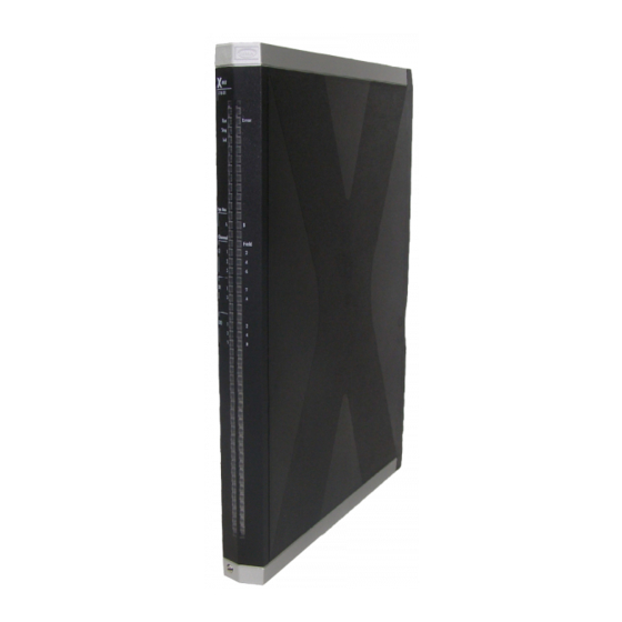
- Page 1 HIMax ® Overspeed Trip Module Manual X-MIO 7/6 01...
- Page 2 All HIMA products mentioned in this manual are protected by the HIMA trade-mark. Unless noted otherwise, this also applies to other manufacturers and their respective products referred to herein. All of the instructions and technical specifications in this manual have been written with great care and effective quality assurance measures have been implemented to ensure their validity.
-
Page 3: Table Of Contents
X-MIO 7/6 01 Table of Contents Table of Contents Introduction Structure and Use of the Manual Target Audience Formatting Conventions 1.3.1 Safety Notes 1.3.2 Operating Tips Safety Intended Use 2.1.1 Environmental Requirements 2.1.2 ESD Protective Measures Residual Risk Safety Precautions Emergency Information Product Description Safety Function... - Page 4 Table of Contents X-MIO 7/6 01 System Cable 3.7.1 System Cable X-CA 005 3.7.2 System Cable X-CA 008 3.7.3 Cable Plug Coding Start-up Mounting 4.1.1 Wiring Inputs Not in Use Mounting and Removing the Module 4.2.1 Mounting a Connector Board 4.2.2 Mounting and Removing the Module Line Monitoring (Short-Circuits and Open-Circuits)
- Page 5 X-MIO 7/6 01 Table of Contents Decommissioning Transport Disposal Appendix Glossary Index of Figures Index of Tables Index HI 801 305 E Rev. 5.00 Page 5 of 72...
-
Page 6: Wiring The Modules Via Connector Boards X-Cb 018 02 And X-Cb 018
Table of Contents X-MIO 7/6 01 Page 6 of 72 HI 801 305 E Rev. 5.00... -
Page 7: Introduction
HI 801 103 E Table 1: Additional Valid Manuals The latest manuals can be downloaded from the HIMA website at www.hima.com. The revision index on the footer can be used to compare the current version of existing manuals with the Internet edition. -
Page 8: Formatting Conventions
1 Introduction X-MIO 7/6 01 Formatting Conventions To ensure improved readability and comprehensibility, the following fonts are used in this document: To highlight important parts Bold: Names of buttons, menu functions and tabs that can be clicked and used in SILworX. System parameter and variables Italics: Literal user inputs... -
Page 9: Operating Tips
X-MIO 7/6 01 1 Introduction 1.3.2 Operating Tips Additional information is structured as presented in the following example: The text corresponding to the additional information is located here. Useful tips and tricks appear as follows: The tip text is located here. HI 801 305 E Rev. -
Page 10: Safety
2 Safety X-MIO 7/6 01 Safety All safety information, notes and instructions specified in this manual must be strictly observed. The product may only be used if all guidelines and safety instructions are adhered to. This product is operated in accordance with SELV or PELV. No imminent danger results from the module itself. -
Page 11: Residual Risk
X-MIO 7/6 01 2 Safety Residual Risk No imminent danger results from a HIMax module itself. Residual risk may result from: Faults in the engineering Faults in the user program Faults in the wiring Safety Precautions Observe all local safety requirements and use the protective equipment required on site. Emergency Information A HIMax controller is a part of the safety equipment of a system. -
Page 12: Product Description
Only sensors (pulse generators) either providing pulses or pulses with a static rotation sense may be connected to the measuring inputs. HIMA recommends using sensors of the same type to reduce divergence among the measured values to the greatest extent possible. -
Page 13: Safety Function
X-MIO 7/6 01 3 Product Description Safety Function The module monitors the rotation speed of a turbine, independently of the HIMax overall system and the user program. The module trips the turbine via the digital outputs . Depending on the measuring input, the module determines the rotation speed and direction of a sensor (pulse generator) with safety-related accuracy. -
Page 14: Type Label
3 Product Description X-MIO 7/6 01 Type Label The type label specifies the following important details: Product name Mark of conformity Bar code (2D or 1D code) Part number (Part-No.) Hardware revision index (HW Rev.) ... -
Page 15: Structure
X-MIO 7/6 01 3 Product Description Structure The chapter is structured as follows: Description of the inputs and outputs Block diagram Indicators (module) Specifications Connector boards System cable The safety-related 1oo2 processor system for the I/O module performs the following functions: ... -
Page 16: Reset Input
3 Product Description X-MIO 7/6 01 3.4.3 Reset Input The module is equipped with a digital reset input (DI 01). The reset input is used for the following purposes: To reset the module after the trip function was triggered. A rising edge at the reset input resets the trip function. -
Page 17: Block Diagram
X-MIO 7/6 01 3 Product Description 3.4.6 Block Diagram The following block diagram shows the structure of the overspeed trip module: Field Zone: Signaling Device Field Zone: Sensors on Measuring Input 1 Field Zone: Actuators, e.g., Solenoid Valves Interface Field Zone: Control Circuit Devices of Type 3 Safety-Related Processor System Field Zone: Reset System Busses... -
Page 18: Indicators
3 Product Description X-MIO 7/6 01 3.4.7 Indicators The following figure shows the LED indicators for the module. Figure 3: Indicators Page 18 of 72 HI 801 305 E Rev. 5.00... -
Page 19: Module Status Indicators
X-MIO 7/6 01 3 Product Description The LEDs indicate the operating state of the output module. The LEDs on the module are divided into three groups: Module status indicators (Run, Error, Stop, Init) System bus indicators (A, B) ... -
Page 20: System Bus Indicators
3 Product Description X-MIO 7/6 01 3.4.9 System Bus Indicators The system bus LEDs are labeled Sys Bus. Color Status Description Green Physical and logical connection to the system bus module in slot 1. Blinking1 No physical connection to the system bus module in slot 1. -
Page 21: Product Data
X-MIO 7/6 01 3 Product Description Product Data General Supply voltage 24 VDC, -15...+20 %, r ≤ 5 %, SELV, PELV Current input min. 0.5 A at 24 VDC without load max. 12 A at 24 VDC Operating temperature 0...+60 °C Storage temperature -40...+85 °C Humidity... -
Page 22: Table 9: Specifications For The Measuring Inputs
3 Product Description X-MIO 7/6 01 Inputs for measuring the frequency Number of measuring inputs 3 inputs respectively, CI01+...CI03+ with one common ground CI- (galvanically isolated from the system bus) Number of inputs, static rotation Control circuit devices of type 3 in accordance with direction signal EN 61131-2 DRI01+...DRI03+... -
Page 23: Table 11: Specifications For Digital Inputs
X-MIO 7/6 01 3 Product Description Digital inputs Number of inputs (number of channels) 3 + 1 reset input, unipolar reference pole L-, non-galvanically isolated from one another Type of input Current sinking logic, 24 V, type 3 in accordance with IEC 61131-2 Rated input voltage 0...24 V Input voltage operating range... -
Page 24: Table 13: Specifications For The Digital Outputs
3 Product Description X-MIO 7/6 01 Digital outputs Number of outputs (number of channels) 5, unipolar with ground L-, non-galvanically isolated Output voltage ≥ L+ minus internal voltage drop Voltage drop (with high level) 2.2 V at 2 A output current Nominal rated current (with high level) 1.6 A, range 0.01...2 A Total permissible current... -
Page 25: Connector Boards
X-MIO 7/6 01 3 Product Description Connector Boards A connector board connects the overspeed trip module to the field zone. Module and connector board form together a functional unit. Insert the connector board into the appropriate slot prior to mounting the module. The following connector boards are available for the overspeed trip module: Connector board Description... -
Page 26: Coding Of X-Cb 018 Connector Boards
3 Product Description X-MIO 7/6 01 Male Connector Recess Coding Wedge Prepared Male Connector Recess Guideway for Coding Wedge Figure 5: Coding Example Coded I/O modules can be plugged in to uncoded connector boards. Uncoded I/O modules cannot be plugged in to coded connector boards. 3.6.2 Coding of X-CB 018 Connector Boards Table 16: Position of Coding Wedges... -
Page 27: Connector Boards With Screw Terminals
X-MIO 7/6 01 3 Product Description 3.6.3 Connector Boards with Screw Terminals Redundant Triple redundant X-CB 018 02 X-CB 018 06 I/O Module Plug Connection to the Field Zone (Screw Terminal Connector Block) Figure 6: Connector Boards with Screw Terminals HI 801 305 E Rev. -
Page 28: Terminal Assignment For Connector Boards With Screw Terminals
3 Product Description X-MIO 7/6 01 3.6.4 Terminal Assignment for Connector Boards with Screw Terminals Designation Signal SCI01+ CI01+ DRI01+ CI01- Designation Signal SCI02+ CI02+ DRI02+ CI02- Designation Signal SCI03+ CI03+ DRI03+ CI03- Designation Signal Designation Signal SDI01+ SDI02+ DI01+ DI02+ DI01- DI02-... -
Page 29: Connector Boards With Cable Plug
X-MIO 7/6 01 3 Product Description 3.6.5 Connector Boards with Cable Plug Redundant Triple redundant X-CB 018 04 X-CB 018 07 I/O Module Plug Connection to the Field Zone Left Cable Plug X1 in Row 32 Connection to the Field Zone Left Cable Plug X1 in Row 1 Connection to the Field Zone Right Cable Plug X2 in Row 32... -
Page 30: Pin Assignment For Connector Boards With Cable Plug
X-MIO 7/6 01 3.6.6 Pin Assignment for Connector Boards with Cable Plug HIMA provides ready-made system cables for use with these connector boards, see Chapter 3.7. The cable plug and the connector boards are coded. Connector pin assignment! The following table describes the connector pin assignment for the system cable plug. -
Page 31: Cable Plug X2
X-MIO 7/6 01 3 Product Description 3.6.6.2 Cable Plug X2 Connect system cable X-CA 008 to cable plug X2. Pin assignment Signal Number Signal Number Signal Color Reserved Reserved Reserved Reserved DO1+ DO1- DO2+ DO2- DO3+ DO3- DO4+ DO4- DO5+ DO5- Table 20: Pin Assignment for the System Cable Plug X2 HI 801 305 E Rev. -
Page 32: System Cable
3 Product Description X-MIO 7/6 01 System Cable The following system cables are necessary for cable plugs X1 and X2: Cable plug System cable X1, left cable plug (Figure 7) X-CA 005 X2, right cable plug (Figure 7) X-CA 008 Table 21: Necessary System Cables 3.7.1 System Cable X-CA 005... -
Page 33: System Cable X-Ca 008
X-MIO 7/6 01 3 Product Description The system cable is available in the following standard length: System cable Description Length X-CA 005 01 8 Coded cable plugs on both sides X-CA 005 01 15 15 m X-CA 005 01 30 30 m Table 23: Available System Cables X-CA 005 01 3.7.2... -
Page 34: Cable Plug Coding
3 Product Description X-MIO 7/6 01 The system cable is available in the following standard length: System cable Description Length X-CA 008 01 8 Coded cable plugs on both sides X-CA 008 01 15 15 m X-CA 008 01 30 30 m Table 25: Available System Cables X-CA 008 01 3.7.3... -
Page 35: Start-Up
- If shielded cables are used, connect the shielding on the module side to the cable shield rail (use SK 20 shield connection terminal block or similar). - When using stranded wires, HIMA recommends fastening ferrules to the wire ends. The terminals must be suitable for fastening the cross-sections of the cables in use. -
Page 36: Mounting And Removing The Module
4 Start-up X-MIO 7/6 01 Mounting and Removing the Module When replacing an existing module or mounting a new one, follow the instructions given in this chapter. When removing the module, the connector board remains in the HIMax base plate. This saves additional wiring effort since all field terminals are connected via the connector board of the module. -
Page 37: Figure 11: Example Of How To Secure The Mono Connector Board With Captive Screws
X-MIO 7/6 01 4 Start-up Figure 11: Example of how to Secure the Mono Connector Board with Captive Screws These instructions also apply for redundant connector boards. The number of slots used varies in accordance with the connector board type. The number of captive screws depends on the connector board type. -
Page 38: Mounting And Removing The Module
4 Start-up X-MIO 7/6 01 4.2.2 Mounting and Removing the Module This chapter describes how to mount and remove the HIMax module. A module can be mounted and removed while the HIMax system is operating. NOTICE Damage to bus and power sockets due to module jamming! Failure to observe this can damage the controller. -
Page 39: Figure 12: Mounting And Removing A Module
X-MIO 7/6 01 4 Start-up Inserting and Removing a Module Securing and Releasing a Module Swiveling a Module in and out Figure 12: Mounting and Removing a Module If the HIMax system is operating, do not open the cover plate of the fan rack for more than a few minutes (<... -
Page 40: Line Monitoring (Short-Circuits And Open-Circuits)
4 Start-up X-MIO 7/6 01 Line Monitoring (Short-Circuits and Open-Circuits) The module monitors the sensors (pulse generators) connected to the measuring inputs for short-circuits (SC) and open-circuits (OC) by monitoring the currents of the sensor supplies. To this end, the parameters SC Limit [mA] and OC Limit [mA] must be configured in accordance with the sensors used. -
Page 41: Overspeed Trip Module Sampling
X-MIO 7/6 01 4 Start-up Overspeed Trip Module Sampling The following chapters describe how the input signals are sampled. The overspeed detection and following triggering of the trip function is independent of the overall HIMax system and the user program. X-MIO 7/6 01 CI 01 CI 02... -
Page 42: 2Oo3 Evaluation
4 Start-up X-MIO 7/6 01 4.4.1 2oo3 Evaluation For the 2oo3 evaluation, at least two of the three input signals must be sampled without errors. The following actions are performed if one of the input signals cannot be sampled without errors: ... -
Page 43: Trip Function
X-MIO 7/6 01 4 Start-up 4.4.4 Trip Function The trip function evaluates the external and internal trip signals. The internal trip signals are generated if the thresholds for the turbine rotation speed and acceleration are violated. The external trip signals are signals that are read at the digital inputs (DI 02...DI 04) and generated by external devices, e.g., machine monitoring systems. -
Page 44: Configuring The Overspeed Trip Module In Silworx
4 Start-up X-MIO 7/6 01 Configuring the Overspeed Trip Module in SILworX The module is configured in the Hardware Editor of the SILworX programming tool. Observe the following points when configuring the module: To diagnose the module and channels, both the system parameters and the measured value can be evaluated within the user program. -
Page 45: The Module Tab In The Detail View For The Redundancy Group
X-MIO 7/6 01 4 Start-up 4.5.1 The Module Tab in the Detail View for the Redundancy Group The Module tab contains the system parameters for the overspeed trip module: Name Description Enter these statuses and parameters directly in the Hardware Editor. Name Module name Spare Module... -
Page 46: The Module Tab In The Detail View For The Individual Modules
4 Start-up X-MIO 7/6 01 4.5.2 The Module Tab in the Detail View for the Individual Modules The Module tab contains the system parameters for the overspeed trip module: Name Description Enter these statuses and parameters directly in the Hardware Editor. Name Module name Name... - Page 47 X-MIO 7/6 01 4 Start-up Name Data Description type Module Status DWORD Status of the module Coding Description 0x00000001 Module fault 0x00000002 Temperature threshold 1 exceeded 0x00000004 Temperature threshold 2 exceeded 0x00000008 Incorrect temperature value 0x00000010 Voltage on L1+ is defective 0x00000020 Voltage on L2+ is defective 0x00000040...
-
Page 48: Table 27: Module Tab In The Hardware Editor
4 Start-up X-MIO 7/6 01 Name Data Description type Timestamp [µs] DWORD Microsecond fraction of the timestamp. Time point of the sampling performed by the processor system of the I/O module. Timestamp [s] DWORD Second fraction of the timestamp. Time point of the sampling performed by the processor system of the I/O module. -
Page 49: Tab: I/O Submodule Do 02
X-MIO 7/6 01 4 Start-up 4.5.3 Tab: I/O Submodule DO 02 The I/O Submodule DO 02 tab contains the following system parameters. Name Description Enter these statuses and parameters directly in the Hardware Editor. Name Module name Output Noise Blanking Allow output noise blanking performed by the output module (activated/deactivated). -
Page 50: Tab: I/O Submodule Di 02
4 Start-up X-MIO 7/6 01 4.5.5 Tab: I/O Submodule DI 02 The I/O Submodule DI 02 tab contains the following system parameters. Name Description Enter these statuses and parameters directly in the Hardware Editor. Name Module name Name Data Description type The following statuses and parameters can be assigned global variables and used in the user program. -
Page 51: Tab: I/O Submodule Di 02: Channels
X-MIO 7/6 01 4 Start-up 4.5.6 Tab: I/O Submodule DI 02: Channels The I/O Submodule DI 02: Channels tab contains the following system parameters for each input. Global variables can be assigned to the statuses and parameters with -> and used in the user program. -
Page 52: Tab: I/O Submodule Ct 03
4 Start-up X-MIO 7/6 01 4.5.7 Tab: I/O Submodule CT 03 The I/O Submodule CT 03 tab contains the following system parameters. Name Description Enter these statuses and parameters directly in the Hardware Editor. Name Module name Supply Used Activated: CI supply errors affect the ->... -
Page 53: Tab: I/O Submodule Ct 03: Channels
X-MIO 7/6 01 4 Start-up 4.5.8 Tab: I/O Submodule CT 03: Channels The I/O Submodule CT 03: Channels tab contains the following system parameters for each measuring input. Global variables can be assigned to the statuses and parameters with -> and used in the user program. -
Page 54: Submodule Status Do 02 [Dword]
4 Start-up X-MIO 7/6 01 4.5.9 Submodule Status DO 02 [DWORD] Coding of the Submodule Status Coding Description 0x00000001 Fault in hardware unit (submodule) 0x00000002 Reset of an I/O bus 0x00000004 Faults detected while configuring the hardware 0x00000080 Reset of CS monitoring (Chip Select monitoring) 0x00800000 Voltage monitoring of WD1: voltage error 0x01000000... -
Page 55: Submodule Status Ct 03 [Dword]
X-MIO 7/6 01 4 Start-up 4.5.11 Submodule Status CT 03 [DWORD] Coding of the Submodule Status Coding Description 0x00000001 Fault in hardware unit (submodule) 0x00000004 Faults detected while configuring the hardware 0x00010000 Internal error 0x00020000 Internal error 0x00040000 Internal error 0x00080000 Internal error 0x00200000... -
Page 56: Diagnostic Status [Dword]
4 Start-up X-MIO 7/6 01 4.5.12 Diagnostic Status [DWORD] Coding of the variable Diagnostic Status. Description Diagnostic values are indicated consecutively. Bit-coded temperature status 0 = normal Bit0 = 1 : Temperature threshold 1 has been exceeded Bit1 = 1 : Temperature threshold 2 has been exceeded Bit2 = 1 : Fault in temperature measurement Measured temperature (10 000 digits/ °C) Bit-coded voltage status... -
Page 57: Table 37: Diagnostic Information [Dword]
X-MIO 7/6 01 4 Start-up Description 1201...1204 Channel status of digital inputs 1...4, I/O unit: = 2 Coding Description 0x0001 Fault occurred in hardware unit (submodule). 0x0800 Channel fault, defective supply status 0x1000 Connection fault I/O bus A 0x2000 Connection fault I/O bus A 0x4000 Channel fault while testing the digital input circuit A 0x8000... -
Page 58: Variants
4 Start-up X-MIO 7/6 01 Variants This chapter describes the proper wiring of the module in safety-related applications. The connection variants specified here are permitted. The module is wired via connector boards. NOTE Damage to the module! Reverse polarity of the inputs and outputs damages the module and thus must be avoided under all circumstances. -
Page 59: Figure 14: Wiring X-Mio 7/6 01
X-MIO 7/6 01 4 Start-up 4.6.1 Wiring the Modules via Connector Boards X-CB 018 02 and X-CB 018 06 The following figure only depicts the wiring for one module. The inputs and outputs of the redundant modules are connected in parallel via the connector board to the sensors and actuators. -
Page 60: Wiring The Modules Via Fta Using System Cables
4 Start-up X-MIO 7/6 01 4.6.2 Wiring the Modules via FTA using System Cables The following figure only depicts the wiring for one module. The inputs and outputs of the redundant modules are connected in parallel via connector boards to the sensors and actuators. Warning Signal Device Input for Measuring the Rotation Speed Actuators DO 01...05 e.g., Solenoid Valves... -
Page 61: Operation
X-MIO 7/6 01 5 Operation Operation The module runs within a HIMax base plate and does not require any specific monitoring. Handling Direct handling of the module is not foreseen. The module is operated from within the PADT, e.g., for forcing the measuring inputs. For more details, refer to the SILworX documentation. -
Page 62: Maintenance
6.1.1 Loading the Operating System HIMA is continuously improving the operating system of the module. HIMA recommends to use system downtimes to load the current version of the operating system into the module. For detailed instructions on how to load the operating system, see the system manual and the online help. -
Page 63: Decommissioning
X-MIO 7/6 01 7 Decommissioning Decommissioning To decommission the module, remove it from the base plate. For more information, see Mounting and Removing the Module. HI 801 305 E Rev. 5.00 Page 63 of 72... -
Page 64: Transport
8 Transport X-MIO 7/6 01 Transport To avoid mechanical damage, HIMax components must be transported in packaging. Always store HIMax components in their original product packaging. This packaging also provides protection against electrostatic discharge. Note that the product packaging alone is not suitable for transport. -
Page 65: Disposal
9 Disposal Disposal Industrial customers are responsible for correctly disposing of decommissioned HIMax hardware. Upon request, a disposal agreement can be arranged with HIMA. All materials must be disposed of in an ecologically sound manner. HI 801 305 E Rev. 5.00... - Page 66 9 Disposal X-MIO 7/6 01 Page 66 of 72 HI 801 305 E Rev. 5.00...
-
Page 67: Appendix
X-MIO 7/6 01 Appendix Appendix Glossary Term Description Address Resolution Protocol: Network protocol for assigning the network addresses to hardware addresses Analog Input Connector Board Connector board for the HIMax module Communication module Cyclic Redundancy Check Digital Input Digital Output Electromagnetic Compatibility European Norm ElectroStatic Discharge... -
Page 68: Index Of Figures
Appendix X-MIO 7/6 01 Index of Figures Figure 1: Sample Type Label Figure 2: Block Diagram Figure 3: Indicators Figure 4: Views Figure 5: Coding Example Figure 6: Connector Boards with Screw Terminals Figure 7: Connector Boards with Cable Plug Figure 8: System Cable X-CA 005 01 n Figure 9:... -
Page 69: Index Of Tables
X-MIO 7/6 01 Appendix Index of Tables Table 1: Additional Valid Manuals Table 2: Environmental Requirements Table 3: Module Inputs and Outputs Table 4: Blinking Frequencies of LEDs Table 5: Module Status Indicators Table 6: System Bus Indicators Table 7: I/O Indicators Table 8: Product Data... -
Page 70: Index
Appendix X-MIO 7/6 01 Index connector board ..........25 module status indicators......19 with cable plug.........29 specficiations with screw terminals ........27 supply ............. 22 diagnosis specifications I/O indicators ...........20 inputs ............23 system bus indicators......20 supply ............. 23 digital outputs..........24 Page 70 of 72 HI 801 305 E Rev. - Page 72 HI 801 305 E © 2012 HIMA Paul Hildebrandt GmbH + Co KG HIMax and SILworX are registered trademark of: HIMA Paul Hildebrandt GmbH + Co KG Albert-Bassermann-Str. 28 68782 Brühl, Germany Phone +49 6202 709-0 +49 6202 709-107 HIMax-info@hima.com...
Need help?
Do you have a question about the HIMax X-MIO 7 01 and is the answer not in the manual?
Questions and answers