Vaisala CARBOCAP GM70 User Manual
Hand-held carbon dioxide meter
Hide thumbs
Also See for CARBOCAP GM70:
- User manual (68 pages) ,
- User manual (49 pages) ,
- User manual (60 pages)
Table of Contents
Advertisement
Quick Links
Advertisement
Table of Contents

Related Manuals for Vaisala CARBOCAP GM70


Summary of Contents for Vaisala CARBOCAP GM70
- Page 1 USER'S GUIDE ® Vaisala CARBOCAP Hand-Held Carbon Dioxide Meter GM70 M010139EN-D...
- Page 2 The contents are subject to change without prior notice. Please observe that this manual does not create any legally binding obligations for Vaisala towards the customer or end user. All legally binding commitments and agreements are included exclusively in the applicable supply contract or Conditions of...
-
Page 3: Table Of Contents
Trademarks ............. 9 License Agreement ..........9 Warranty ..............10 CHAPTER 2 PRODUCT OVERVIEW ............11 ® Introduction to Vaisala CARBOCAP Hand-Held Carbon Dioxide Meter GM70........ 11 Basic Features of the GM70....... 11 Interchangeable Probes ........12 Tool for Adjustments .......... 12 Parts Description.......... - Page 4 User's Guide_________________________________________________________ CHAPTER 4 MEASURING CARBON DIOXIDE...........19 Taking Measurements (Diffusion Sampling) ..19 Taking Measurements (Pump Aspirated Sampling)...............20 Measuring Other Parameters Simultaneously..22 CHAPTER 5 BUTTONS, DISPLAYS, AND MENUS ........23 Buttons and Navigation........23 Basic Display............24 Graphical Display..........25 Menus..............25 CHAPTER 6 SETTINGS ................27 Setting Actual Pressure Value and Unit....27 Setting Actual Temperature Value and Unit ..28 Display Settings ............29...
- Page 5 Transferring Recorded Data to PC ...... 44 Real-Time Monitoring with PC......44 CHAPTER 9 FIELD CHECKING OF FIXED TRANSMITTERS....45 Field Checking of the Vaisala GMD/W20 Series Transmitters (Diffusion Sampling) ...... 45 Field Checking of the Vaisala GMD/W20 Series Transmitters (Pump Aspirated Sampling) ..46 Field Checking of the GMT220 (Without a Display) ..........
- Page 6 User's Guide_________________________________________________________ Technical Support..........62 Return Instructions ..........62 Vaisala Service Centers........63 CHAPTER 13 TECHNICAL SPECIFICATIONS ..........65 GM70 Hand-Held Carbon Dioxide Meter .....65 General............65 Electromagnetic Compatibility ......65 GMP221/222 Probes..........66 GMH70 Handle, GM70PUMP.........67 MI70 Indicator ............67 Indicator General ..........67 Battery Pack ...........68 Accessories............68 Dimensions in mm (inch) ........69...
- Page 7 Measuring Ranges ..........66 Table 5 Accuracy Specifications.......... 66 Table 6 Other Specifications ..........66 Table 7 General Specifications..........67 Table 8 General Specifications..........67 Table 9 Battery Pack Specifications ........68 Table 10 Accessories Table ..........68 VAISALA __________________________________________________________ 5...
- Page 8 User's Guide_________________________________________________________ This page intentionally left blank. 6 ______________________________________________________ M010139EN-D...
-
Page 9: Chapter 1 General Information
Vaisala CARBOCAP Hand-Held Carbon Dioxide Meter GM70. Feedback Vaisala Customer Documentation Team welcomes your comments and suggestions on the quality and usefulness of this publication. If you find errors or have other suggestions for improvement, please indicate the chapter, section, and page number. -
Page 10: Safety
ESD Protection Electrostatic Discharge (ESD) can cause immediate or latent damage to electronic circuits. Vaisala products are adequately protected against ESD for their intended use. However, it is possible to damage the product by delivering electrostatic discharges when touching, removing, or inserting any objects inside the equipment housing. -
Page 11: Recycling
Microsoft Corporation in the United States and/or other countries. License Agreement All rights to any software are held by Vaisala or third parties. The customer is allowed to use the software only to the extent that is provided by the applicable supply contract or Software License Agreement. -
Page 12: Warranty
Products should Vaisala so require, be sent to the works supplied hereunder, which obligations of Vaisala or to such other place as Vaisala may liabilities are hereby expressly cancelled and indicate in writing, freight and insurance waived. Vaisala's liability... -
Page 13: Chapter 2 Product Overview
- Data logging possibility - Tool for checking the reading of fixed CO transmitters - Tool for adjusting Vaisala GM220 series probes - Possibility for an analog output (voltage signal 0...1 V) - Optional ready-to-use Windows software enabling easy way to handle measurement data... -
Page 14: Interchangeable Probes
User's Guide_________________________________________________________ Interchangeable Probes By selecting the right probe you can choose the measuring range that best fits for your application. The calibrated measuring ranges varies from 0...2000 ppm to 0... 20% concentrations of CO . Refer to Chapters 2 and 13 for more details. -
Page 15: Parts Description
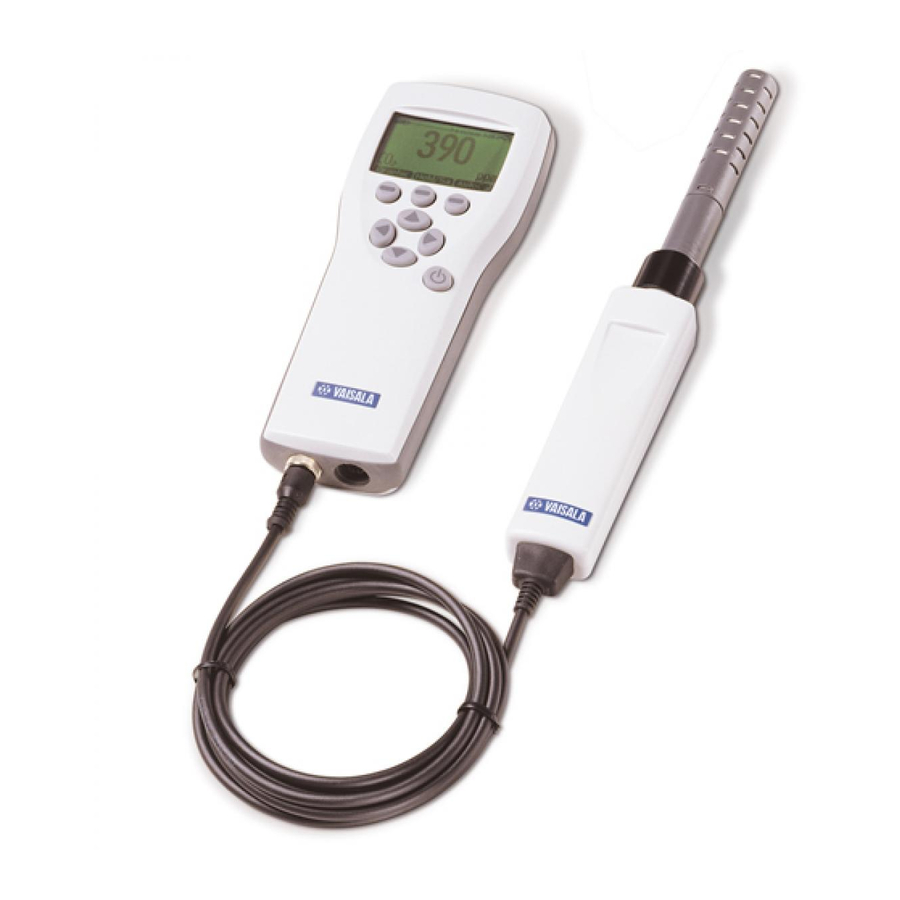
Chapter 2 _____________________________________________ Product Overview Parts Description 0505-221 Figure 1 GM70 Parts The following numbers refer to Figure 1 above: 1 = MI70 indicator VAISALA _________________________________________________________ 13... -
Page 16: Probes
User's Guide_________________________________________________________ 2 = Recharger connector 3 = Connector ports I and II for probes and cables 4 = Probe GMP221 or GMP222 5 = Probe fastener 6 = Handle GMH70 7 = Adjustment button 8 = Gas outlet 9 = ON/OFF switch 10 = Gas inlet 11 = Measuring chamber 12 = Probe GMP221 or GMP222... -
Page 17: Gm70Pump For Aspirated Sampling
GM70PUMP is designed for checking of fixed CO transmitters and for sampling from locations difficult to access. GM70PUMP is connected to a MI70 indicator which displays the measurement result. Pump system is powered through the MI70 indicator. VAISALA _________________________________________________________ 15... - Page 18 User's Guide_________________________________________________________ This page intentionally left blank. 16 _____________________________________________________ M010139EN-D...
-
Page 19: Preparations Before Use
- Duration of recharging depends on the charge level of the battery pack being 4 hours typical. The recommended first recharging time is 6 hours. The battery pack is full when the battery symbol stops to roll. Disconnect the recharger. VAISALA _________________________________________________________ 17... -
Page 20: Turning On And Setting Language, Date, And Time
User's Guide_________________________________________________________ Turning On and Setting Language, Date, and Time Connect the probe handle (or the connector from the GM70PUMP) to either of the connector ports of the indicator. Press the button. Select the language by using buttons. Confirm by pressing SELECT The default date presentation format is:... -
Page 21: Measuring Carbon Dioxide
Connect the probe cable to the MI70 indicator's connector port. Press button. POWER ON/OFF Wait for about 15 seconds to get the reading. For the most accurate readings wait for 15 minutes to reach the full operating state of the GM70. VAISALA _________________________________________________________ 19... -
Page 22: Taking Measurements (Pump Aspirated Sampling)
User's Guide_________________________________________________________ Install the probe to the measuring position. Avoid exhaling near the probe as this increases the CO concentration. The basic display opens, allow the reading to stabilize. CAUTION Handle the probe carefully. Strong impact or falling can damage the probe. If you need to disconnect the probe, first press POWER button to turn the indicator OFF. -
Page 23: Figure 2 Properly Connecting The Gm70Pump
When using the pump aspirated system it is recommended to power the system by using the recharger connected to a wall socket. NOTE The battery indicator of the MI70 display does NOT show the actual recharge level when the pump is in operation. VAISALA _________________________________________________________ 21... -
Page 24: Measuring Other Parameters Simultaneously
User's Guide_________________________________________________________ Measuring Other Parameters Simultaneously Connect Vaisala interchangeable dewpoint (DMP) or humidity (HMP) probe to the MI70 indicator's other connector port to have simultaneous humidity measurement. Connect the DMP70/HMP70 probe to the other connector port in the bottom of the indicator. -
Page 25: Buttons, Displays, And Menus
The following numbers refer to Figure 4 above: 1 = To open a menu view: - Press an arrow button - Press this shortcut button 2 = Shortcut buttons 3 = Arrow buttons 4 = Power ON/OFF VAISALA _________________________________________________________ 23... -
Page 26: Basic Display
User's Guide_________________________________________________________ Press down and hold the button (1) until POWER ON/OFF the indicator turns on/off. Press the buttons (2) to activate the function SHORTCUT above the button. Press any of the buttons (3) to open the path ARROW for the . -
Page 27: Graphical Display
If this MENU happens, start with item 1 again. Move in the menus by using buttons. Select the item with button. Press to return to the previous level. returns back to normal operation. EXIT VAISALA _________________________________________________________ 25... -
Page 28: Figure 6 Menus
User's Guide_________________________________________________________ 0505-226 Figure 6 Menus The following numbers refer to Figure 6 above: 1 = Main menu 2 = Display menu 3 = Functions menu 4 = Recording/Viewing menu 5 = Environment menu 6 = Settings menu 26 _____________________________________________________ M010139EN-D... -
Page 29: Chapter 6 Settings
UNIT Set the pressure value by using buttons. Press to save the value. Press to change the pressure unit. Default unit is UNIT hPa. Press to return to the basic display. EXIT 0505-227 Figure 7 Environment Menu VAISALA _________________________________________________________ 27... -
Page 30: Setting Actual Temperature Value And Unit
User's Guide_________________________________________________________ Setting Actual Temperature Value and Unit For achieving the most accurate measurements, the actual temperature value should be set to the GM70. The acceptable temperature range is -20...60ºC. Follow the instructions below: Open the , press MENU OPEN. Select with press... -
Page 31: Display Settings
EXIT Press , if you want to check the environment settings, otherwise press NOTE Measurement units (ppm and %) express the CO concentration by gas volume. 1% CO = 10 000 ppm CO VAISALA _________________________________________________________ 29... -
Page 32: Rounding
User's Guide_________________________________________________________ Rounding When using % units, you can select two or three decimal display by using the Rounding function. The default setting is rounding off (= three decimal display). Open the , press MENU OPEN. Select , press ►Display Select Rounding Press... -
Page 33: Graphic History
To zoom in on the curve, press the arrow button . To zoom out, press the button . To move the curve in horizontal directions, press the buttons Press to return to the basic display. BACK EXIT User Interface 0505-229 Figure 9 User Interface Settings Menus VAISALA _________________________________________________________ 31... -
Page 34: Selecting Language
User's Guide_________________________________________________________ Selecting Language You can select any of the following languages as a user interface language: English, German, French, Finnish, Spanish or Swedish. Open the , press MENU OPEN. Select , press ►Settings Select , press ►User interface Select , press Language Select the language you want, press... -
Page 35: Changing The Shortcut Keys
4. Press to return to the basic display. EXIT 0505-230 Figure 10 Changing the Shortcut Keys The following number refers to Figure 10 above: -shortcut key replaced by pressure setting Hold/Save shortcut key VAISALA _________________________________________________________ 33... -
Page 36: Key Click And Backlight On Key Press
User's Guide_________________________________________________________ Key Click and Backlight On Key Press Open the , press MENU OPEN. Select , press ►Settings Select , press ►User interface To turn the sound effect while pressing the buttons OFF or ON, select and press Key click ON/OFF To turn the backlight effect while pressing the buttons OFF or ON, select... -
Page 37: Device Information
The following numbers refer to Figure 11 above: 1 = Software version of the MI70 indicator 2 = Serial number of the MI70 indicator 3 = Software version of the probe 4 = Location of the last adjustment (alternatives: Vaisala, GM70, or GMK220) VAISALA _________________________________________________________ 35... -
Page 38: Reverting Factory Settings
User's Guide_________________________________________________________ Reverting Factory Settings Factory settings of the indicator only can be reverted to clear all changed settings and data memory of the indicator. Reverting factory settings of the indicator does not affect the probe calibration. Factory calibration of the probe cannot be reverted if adjustment is made (see Chapter 10 Calibrating and Adjusting the Probes on page 49). - Page 39 A note picture sign appears on the upper left corner of the basic display. When the alarm level is reached, you can stop alarming by pressing . To reactivate the alarm function, answer . To stop the alarm function completely, answer VAISALA _________________________________________________________ 37...
- Page 40 User's Guide_________________________________________________________ This page intentionally left blank. 38 _____________________________________________________ M010139EN-D...
-
Page 41: Analog Output Connection
Connect the analog output signal cable connector to the indicator base connector. Connect the screw terminal block as follows: Brown wire: common wire (-) Yellow-green wire: signal (+) Open the , press MENU OPEN. Select , press ►Functions VAISALA _________________________________________________________ 39... - Page 42 User's Guide_________________________________________________________ Select , press ►Analog output Select to set the value for the 0.0V output signal, 0.0 V press (If the analog output is ON, take it OFF). Set the low value by using the arrow buttons. Press to make the setting. Select to set the value for the 1.0V output signal, 1.0V...
-
Page 43: Chapter 8 Recording Data
, select MENU ►Recording/Viewing Select , press ►Record data To change interval, select , press Interval Select the measurement interval with the arrow buttons. The measurement intervals and the maximum recording times are shown in the following table. VAISALA _________________________________________________________ 41... - Page 44 User's Guide_________________________________________________________ Measurement interval Maximum recording duration (= memory full) 1 second 45 minutes 5 seconds 3 hours 15 seconds 11 hours 30 seconds 22 hours 1 minute 45 hours 5 minutes 9 days 15 minutes 28 days 30 minutes 56 days 1 hour 113 days...
-
Page 45: Stop Recording
Open the , press MENU OPEN. Select , press ►Recording/Viewing Select , press to see the amount of Memory status SHOW memory in use and the estimated free space. To return to the basic display, press EXIT VAISALA _________________________________________________________ 43... -
Page 46: Deleting All Recorded Files
Excel) for modification. Real-Time Monitoring with PC You can monitor the GM70 readings directly with a PC by using the MI70 Link program. The MI70 Link program can be ordered from Vaisala, see list of accessories on page 68. 44 _____________________________________________________ M010139EN-D... -
Page 47: Field Checking Of Fixed Transmitters
Chapter 9 ______________________________ Field Checking of Fixed Transmitters CHAPTER 9 FIELD CHECKING OF FIXED TRANSMITTERS Field Checking of the Vaisala GMD/W20 Series Transmitters (Diffusion Sampling) 0505-235 Figure 15 Location of the MI70 Connector Ports The following number refers to Figure 15 above:... -
Page 48: Field Checking Of The Vaisala Gmd/W20 Series Transmitters (Pump Aspirated Sampling)
Compare the readings. In case there is a need for an adjustment, send the transmitter to a Vaisala Service Center to be adjusted or make an adjustment by using a calibration software kit (19222GM). - Page 49 Turn on the MI70 indicator and the GM70PUMP. Compare the readings. In case there is need for an adjustment, send the transmitter to a Vaisala Service Center to be adjusted or make an adjustment by using a calibration software kit (19222GM).
-
Page 50: Field Checking Of The Gmt220 (Without A Display)
Compare the readings of the GM70 and the transmitter probe to be checked. If there is need for an adjustment, please contact Vaisala Service Center or adjust the probe according to the instructions in Chapter 10 Calibrating and Adjusting the Probes on page 49. -
Page 51: Calibrating And Adjusting The Probes
The length of the suitable calibration interval may vary depending on the conditions and frequency of use. Factory Calibration and Adjustment It is recommended to send the GM70 probe to Vaisala Service Centers for accurate calibration and adjustment, see contact information on page 63. -
Page 52: Calibration And Adjustment By The User
User's Guide_________________________________________________________ Calibration and Adjustment by the User The GM70 can be calibrated and fine control adjustment can be carried out by the user. Note that this adjustment does not correspond to the accurate factory adjustment. The user adjustment is recommended only if the reading error is less than 10% of the measuring range in the low-end and less than 20% of the measuring range in the high-end. -
Page 53: Adjustment With Reference Gases
For the adjustment procedure with gases, you need the probe to be adjusted, accurate reference gas(es), a pressure regulator, a flow meter, a field check adapter (can be ordered from Vaisala) and flexible tubing with 3 mm (1/8") inner diameter. Reference Gases To achieve reliable results reference gases shall be traceable to appropriate standards (for example NIST). -
Page 54: Two-Point Adjustment Procedure
User's Guide_________________________________________________________ Two-Point Adjustment Procedure CAUTION Please take special care regarding the following when carrying out the adjustment: - Check that you give the correct reference concentrations in the correct units. - Check that the reading has really stabilized before accepting the reading. - Page 55 The analyzed CO concentration of the reference gas is typically printed on the bottle. Take care that you give the correct value in correct units, as you cannot revert the earlier values after accepting the new values. Press VAISALA _________________________________________________________ 53...
-
Page 56: One-Point Adjustment Procedure
User's Guide_________________________________________________________ 16. Confirm the adjustment, press . By pressing you return to adjustment mode display. (If the difference between the two references is less than 20% of the measuring range of the probe, adjustment cannot be done). 17. Adjustment is complete. Press to return to BACK-EXIT the basic display. - Page 57 12. Confirm the adjustment, press . By pressing you return to adjustment mode display. 13. Adjustment is complete. Press to return to BACK-EXIT the basic display. 14. Shut off the gas flow. 15. Replace the screw onto the adjusting button. VAISALA _________________________________________________________ 55...
-
Page 58: Adjustment With Two Probes
User's Guide_________________________________________________________ Adjustment with Two Probes You need to have two probe handles and two probes: one calibrated probe and the probe to be adjusted. It is recommended to carry out the adjustment in a stable environment and near the concentration values in which the device is used. -
Page 59: Chapter 11 Error Messages
This message can be caused by a considerable high drifting error of the probe. Please, contact Vaisala or send the probe to Vaisala Service, see page 63. Value too high The reference concentration can be at the highest 110% of the maximum value of the probe's measuring range. - Page 60 Switch on power. Adapter error Switch off power and check that the probe is connected properly, see the instructions of Probe error. In case of continuous error, contact Vaisala or send the probe to Vaisala Service, see page 58 _____________________________________________________ M010139EN-D...
-
Page 61: Chapter 12 Maintenance
Turn the probe inside the handle until you feel that a step in the probe connector snaps into the groove of the probe handle connector and locks the probe. Tighten the probe fastener. Turn on the GM70. VAISALA _________________________________________________________ 59... -
Page 62: Changing The Probe Filter
1 = Unscrew the probe fastener (about 5 turns). 2 = Pull the probe out firmly. Changing the Probe Filter Spare filters for the probe can be ordered from Vaisala, see list of accessories on page 68. Remove the plastic grid by pulling it out. -
Page 63: Changing The Battery Pack
Chapter 12 ________________________________________________ Maintenance Changing the Battery Pack New rechargeable battery packs can be ordered from Vaisala. Change the battery pack as follows: Open the back plate of the indicator by opening the screw of the back plate. Remove the old battery pack. Detach the black connector by pulling up carefully from the wires. -
Page 64: Technical Support
User's Guide_________________________________________________________ Technical Support For technical questions, contact the Vaisala technical support: E-mail helpdesk@vaisala.com Phone (int.) +358 9 8949 2789 +358 9 8949 2790 Return Instructions If the product needs repair, please follow the instructions below to speed up the process and avoid extra costs. -
Page 65: Vaisala Service Centers
Please include the Problem Report in the same box. Send the box to: Vaisala Oyj Contact person / Division Vanha Nurmijärventie 21 FIN-01670 Vantaa Finland or to the addresses below: Vaisala Service Centers VAISALA _________________________________________________________ 63... - Page 66 User's Guide_________________________________________________________ This page intentionally left blank. 64 _____________________________________________________ M010139EN-D...
-
Page 67: Technical Specifications
General Specifications Property Description / Value Storage temperature -30...+70°C Storage humidity 0...100%RH non-condensing range Electromagnetic Compatibility Complies with the following standard: EN61326-1:1997+ Am1:1998 + Am2:2001, Electrical equipment for measurement, control and laboratory use - EMC requirements; Generic environment. VAISALA _________________________________________________________ 65... -
Page 68: Gmp221/222 Probes
User's Guide_________________________________________________________ GMP221/222 Probes Table 4 Measuring Ranges Probe Measuring Ranges GMP221 0...2%, 0...3%, 0...5%, 0...10%, 0...20% GMP222 0...2000 ppm, 0...3000 ppm, 0...5000 ppm, 0...7000 ppm, 0...10000 ppm Table 5 Accuracy Specifications Accuracy at 25°C against certified factory references (including repeatability and calibration uncertainty) Probe Accuracy GMP221... -
Page 69: Gmh70 Handle, Gm70Pump
Minimum load resistor 10 kohm to ground Data interface RS232C Data logging capacity 900...2700 real time data points Logging interval 1 s to 12 h Alarm Audible alarm function Housing classification IP54 Weight 400 g Housing material ABS/PC-blend VAISALA _________________________________________________________ 67... -
Page 70: Battery Pack
User's Guide_________________________________________________________ Battery Pack Table 9 Battery Pack Specifications Property Description / Value Operation times continuous use (one 8 h typical at +20°C probe) data logging use (one up to 30 days (1-hour measurement probe) interval) when pump is on 5 h typical Power consumption 10 W max... -
Page 71: Dimensions In Mm (Inch)
Chapter 13 _______________________________________ Technical Specifications Dimensions in mm (inch) 0505-240 Figure 20 Dimensions VAISALA _________________________________________________________ 69... - Page 74 www.vaisala.com...
Need help?
Do you have a question about the CARBOCAP GM70 and is the answer not in the manual?
Questions and answers