Table of Contents
Advertisement
Quick Links
Advertisement
Table of Contents

Related Manuals for Vaisala CARBOCAP GMP231


Summary of Contents for Vaisala CARBOCAP GMP231
- Page 1 USER'S GUIDE Vaisala CARBOCAP® Carbon Dioxide Probe GMP231...
- Page 3 CHAPTER 3 INSTALLATION.................... 20 Thermal Management ............20 Avoiding Condensation ............21 Probe Installation Depth ............21 Dimensions ................22 Recommended Installation ........... 23 Wiring ..................24 Power Supply................24 CHAPTER 4 VAISALA INDUSTRIAL PROTOCOL............25 Overview ................. 25 VAISALA_________________________________________________________________________ 1...
- Page 4 User's Guide _______________________________________________________________________ Physical Interface ..............25 Connecting with a Computer..........26 Installing the Driver for the USB Service Cable .....26 Terminal Application Settings.........27 Serial Commands ..............28 Showing Device Information ..........29 Show Probe Information ............29 Show Serial Number............30 Show Firmware Version ............30 Show Firmware Information ..........30 Show Probe Uptime.............30 Show Command List ............31...
- Page 5 Effect of Environmental Compensations ......74 Limits of Adjustment............75 Adjustment Types ............... 75 C Interface ..............76 Vaisala Industrial Protocol ..........76 MI70 Hand-Held Indicator ..........76 CHAPTER 7 OPERATING WITH MI70 INDICATOR ............77 Overview of MI70 Support ............. 77 Connecting GMP231 to MI70 Indicator.........
- Page 6 User's Guide _______________________________________________________________________ Analog Output Error State .............84 Technical Support ..............84 Product Returns..............84 CHAPTER 9 TECHNICAL DATA ..................85 Specifications .................85 Spare Parts and Accessories ..........87 4 ____________________________________________________________________ M211501EN-C...
-
Page 7: Table Of Contents
_________________________________________________________________________________ List of Figures Figure 1 GMP231 Installed Through a Chamber Wall (Example)..12 Figure 2 GMP231 Parts ................14 ® Figure 3 CARBOCAP Sensor of the GMP231........15 Figure 4 Measurement Inside the Incubator ........16 Figure 5 Probe Installation Depth ............21 Figure 6 Probe Dimensions without Silicone Plug........ - Page 8 User's Guide _______________________________________________________________________ List of Tables Table 1 Manual Revisions ............... 8 Table 2 Related Manuals................. 8 Table 3 Applicable Patents ..............10 Table 4 GMP231 Connector Pinout............24 Table 5 Cable DRW240977..............24 Table 6 Default Serial Interface Settings ..........25 Table 7 Basic Serial Commands ............28 Table 8 Advanced Serial Commands ............29...
- Page 9 - Chapter 3, Installation, provides you with information that is intended to help you install the GMP231. - Chapter 4, Vaisala Industrial Protocol, describes the Vaisala Industrial Protocol implementation of the GMP231. - Chapter 5, I2C Interface, describes the I2C interface implementation of the GMP231.
-
Page 10: Table 1 Manual Revisions
Previous version. Applicable from software version 1.1.0 onward. Added instructions for operation with the MI70 hand-held indicator. Updated description of I C interface and Vaisala Industrial Protocol. Updated description of environmental compensations. Updated instructions for calibration and adjustment. Updated technical specification. - Page 11 ESD Protection Electrostatic Discharge (ESD) can cause immediate or latent damage to electronic circuits. Vaisala products are adequately protected against ESD for their intended use. It is possible to damage the product, however, by delivering an electrostatic discharge when touching an exposed contact on the product.
-
Page 12: Table 3 Applicable Patents
All other trademarks are the property of their respective owners. Software License This product contains software developed by Vaisala. Use of the software is governed by license terms and conditions included in the applicable supply contract or, in the absence of separate license terms and conditions, by the General License Conditions of Vaisala Group. - Page 13 Chapter 1 _________________________________________________________ General Information Warranty Visit our Internet pages for standard warranty terms and conditions: www.vaisala.com/warranty. Please observe that any such warranty may not be valid in case of damage due to normal wear and tear, exceptional operating conditions, negligent handling or installation, or unauthorized modifications.
-
Page 14: Figure 1 Gmp231 Installed Through A Chamber Wall (Example)
PRODUCT OVERVIEW This chapter introduces the GMP231 probe and its features. Introduction to GMP231 The Vaisala CARBOCAP® Carbon Dioxide Probe GMP231 is designed for incubator manufacturers requiring accurate and reliable carbon dioxide measurements and sterilization durability at high temperatures. ®... - Page 15 See section Environmental Compensation on page 17. - Heating to avoid condensation on optical elements. - Analog output: one current output channel (0 ... 20 mA or 4 ... 20 mA). - Digital output: - RS-485 (non-isolated) with Vaisala Industrial Protocol. VAISALA________________________________________________________________________ 13...
-
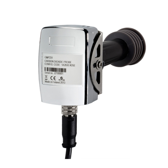
Page 16: Figure 2 Gmp231 Parts
User's Guide _______________________________________________________________________ GMP231 Parts 1403-153 Figure 2 GMP231 Parts 1 = Electronics housing. Contains the main component board, including the digital pressure sensor. 2 = Holes for M4 screws on both sides of the housing. Maximum screw depth 8 mm. Two screws included, type BN 10649 M4. -
Page 17: Figure 3 Carbocap Sensor Of The Gmp231
Chapter 2 ___________________________________________________________ Product Overview Operating Principle of CO Measurement ® The Vaisala CARBOCAP sensor that is used in the GMP231 is a silicon- based, non-dispersive infrared (NDIR) sensor for the measurement of gaseous carbon dioxide. It is especially designed to tolerate high temperatures in standby mode, up to 195 °C (383 °F). -
Page 18: Figure 4 Co 2 Measurement Inside The Incubator
User's Guide _______________________________________________________________________ 1403-161 Figure 4 Measurement Inside the Incubator 1 = Chamber wall. 2 = Chamber interior. 3 = Light source. 4 = Band pass filter. 5 = Ambient air (400 ... 1000 ppm CO 6 = Light absorbed by CO in the incubator gas. - Page 19 Chapter 2 ___________________________________________________________ Product Overview Environmental Compensation GMP231 improves the CO measurement accuracy by applying various environmental compensations. GMP231 compensates for the effects of: - Pressure - Temperature - Background gas oxygen (O ) content - Background gas relative humidity (%RH) Compensation parameters are configured on the order form when ordering the probe, and can later be updated using serial commands, MI70 Indicator, or I...
- Page 20 User's Guide _______________________________________________________________________ Background Gas Compensations Compensation for background gas parameters are based on setpoint values only, as GMP231 has no internal measurement for oxygen concentration or humidity. The default setpoint values are as follows: - Oxygen concentration: 19.7 %O - Relative humidity: 93 %RH.
- Page 21 Chapter 2 ___________________________________________________________ Product Overview Analog Output Overrange Behavior Analog output of the GMP231 has a defined behavior when the values measured by the probe are outside the scaled analog output range: - Output is allowed to go 10% over the scaled range. - Output is set to error state when measured value is more than 10% outside the scaled range.
- Page 22 - The installation tube must be sealed from the chamber side to limit heat conduction, and to prevent CO in the chamber from entering the probe. Vaisala recommends a 44 mm diameter installation tube together with Vaisala’s silicone plug. - If the chamber wall contains heating elements, or has a construction where hot air is circulated inside the wall, design the installation tube so that excessive heat is not conducted to the GMP231.
-
Page 23: Figure 5 Probe Installation Depth
Chapter 3 ________________________________________________________________ Installation Avoiding Condensation The sensor head of the GMP231 is heated during normal operation, which prevents condensation from forming inside the filter and on the optical surfaces. The heating is not on when GMP231 is in standby mode or unpowered. -
Page 24: Figure 6 Probe Dimensions Without Silicone Plug
User's Guide _______________________________________________________________________ Dimensions 118.5 Screw BN 10649 M4 x 8 mm Position only the filter (for 1 mm thick sheet metal inside the heated chamber attachment) 1403-108 Figure 6 Probe Dimensions without Silicone Plug 118.5 Recommended diameter for installation tube 44 mm Screw BN 10649 M4 x 8 mm Position only the filter (for 1 mm thick sheet metal... -
Page 25: Figure 10 Recommended Installation
Chapter 3 ________________________________________________________________ Installation Recommended Installation GMP231 is designed to be installed through a chamber wall, and attached to the chamber chassis using an attachment bracket and the two screw holes on the side of the probe. As the installation depth of the probe inside the chamber is critical (see section Probe Installation Depth on page 21), the mounting method must allow the probe to be positioned exactly. -
Page 26: Table 4 Gmp231 Connector Pinout
Power supply + Ground Shield Vaisala’s standard connection cable for the GMP231 (order code DRW240977) is a 90 cm long cable with female 8-pin M12 connector on one end, and open ended wires on the other. It supports all outputs from the GMP231, and connects the cable shield to the connector chassis. -
Page 27: Table 6 Default Serial Interface Settings
This chapter describes the Vaisala Industrial Protocol implementation of the GMP231. Overview RS-485 line of the GMP231 provides an implementation of the Vaisala Industrial Protocol that can be used for service and configuration use, or for interfacing with the incubator’s control system. The protocol is a plaintext protocol suitable for use both by human operators and automated systems. - Page 28 When connecting using a computer, use the Vaisala USB cable (Vaisala order code 221040) and a suitable terminal application: - If you have not used the Vaisala USB cable before, install the driver before attempting to use the cable. Refer to section Installing the Driver for the USB Service Cable below for detailed instructions.
-
Page 29: Figure 11 Putty Terminal Application
COM port is selected in the Serial or USB line to connect to field. If you are using the PuTTY terminal application supplied by Vaisala, you can press the USB Finder button to open the Vaisala USB Instrument Finder program. -
Page 30: Table 7 Basic Serial Commands
User's Guide _______________________________________________________________________ Serial Commands All commands can be issued either in uppercase or lowercase. In the command examples, the keyboard input by the user is in bold type. The notation <cr> refers to pressing the carriage return (Enter) key on your computer keyboard. -
Page 31: Table 8 Advanced Serial Commands
?? command even while in POLL mode. Do not use the ?? command if you have more than one probe on an RS-485 line. Example: Device : GMP231 Copyright : Copyright (c) Vaisala Oyj 2013. All rights reserved. SW Name : GMP231 SW version : 1.0.1.1537 Snum... - Page 32 User's Guide _______________________________________________________________________ Show Serial Number SNUM<cr> Example: snum Serial number : J1320082 Show Firmware Version VERS<cr> Example: vers GMP231 / 1.1.0.1537 Show Firmware Information SYSTEM<cr> Example: system Device Name : GMP231 SW Name : GMP231 SW version : 1.1.0.1537 Show Probe Uptime Use the TIME command to show how long the probe has been in operation, and what is the current uptime since last reset (in seconds).
- Page 33 Chapter 4 ____________________________________________________ Vaisala Industrial Protocol Show Command List Use the HELP command to show a list of the currently available serial commands. HELP<cr> Example (shows basic commands, advanced commands are not enabled): CLOSE ECHO ERRS FORM HELP INTV PASS...
- Page 34 User's Guide _______________________________________________________________________ Stop Measurement Output You can stop the measurement output by pressing the ESC key or with the S command. Set Output Interval Use the INTV command to change the output interval of the automatically repeating measurement messages. The measurement messages are repeated in the RUN mode, or after the R command has been given.
-
Page 35: Table 9 Form Command Parameters
Chapter 4 ____________________________________________________ Vaisala Industrial Protocol Set Measurement Output Format Use the serial line command FORM to change the measurement message sent by the probe. You can freely define the output message to include the desired parameters, formatting options, text strings, and additional fields. - Page 36 User's Guide _______________________________________________________________________ FORM Command Examples Example of default output (continuous output from RUN mode): CO2= 860 ppm CO2= 861 ppm CO2= 861 ppm Command to set output format as %CO form 3.1 "CO2=" CO2% " " U4 #r #n Output example: CO2= 5.1 %CO2...
- Page 37 Chapter 4 ____________________________________________________ Vaisala Industrial Protocol Changing Measurement Settings Set Compensation Modes You can change the mode of each environmental compensation type using a dedicated serial command. The commands are: - PCMODE for pressure compensation mode. - TCMODE for temperature compensation mode.
- Page 38 User's Guide _______________________________________________________________________ Change Compensation Setpoint Values Use the ENV command to show or set the setpoint values of the environmental compensation parameters. To change a value, give the parameter name and value as arguments to the ENV command. ENV [temp|pres|oxy|hum|xtemp|xpres|xoxy|xhum] [value]<cr> There are four compensation parameters.
- Page 39 Chapter 4 ____________________________________________________ Vaisala Industrial Protocol Example below sets temperature compensation to setpoint mode, and changes temperature setpoint value to 37.2 in RAM. pass 1300 tcmode on T COMP MODE : ON env xtemp 37.2 In eeprom: Temperature (C) : 37.00 Pressure (hPa) : 1013.20...
-
Page 40: Table 11 Selection Of Output Modes
User's Guide _______________________________________________________________________ Configuring Serial Line Operation Set Serial Line Operating Mode Use the SMODE command to set the start-up operating mode of the serial line. SMODE [mode]<cr> where mode = STOP, RUN, or POLL. Table 11 Selection of Output Modes Mode Measurement Output Available Commands... - Page 41 Chapter 4 ____________________________________________________ Vaisala Industrial Protocol Set Serial Line Settings Use the SERI command to set the serial line settings. The new settings will be taken into use when the probe is reset or powered up. SERI [b p d s]<cr>...
- Page 42 User's Guide _______________________________________________________________________ Set Serial Line Response Time With the SDELAY command you can set delay (response time) of the serial line, or view the currently set delay value. SDELAY [delay]<cr> where delay = Serial line delay, range 0 … 255 (milliseconds). Example (set delay to 50 milliseconds): sdelay 50 Serial delay...
- Page 43 Chapter 4 ____________________________________________________ Vaisala Industrial Protocol Calibration Commands NOTE Before calibrating GMP231 using serial line commands, read the instructions in section Calibration and Adjustment on page 73. Make sure that the environmental compensation settings of the GMP231 are properly set for your calibration environment; see section Changing Measurement Settings on page 35.
- Page 44 User's Guide _______________________________________________________________________ Example (show current user adjustment status – no adjustment done): pass 1300 cco2 1.Ref. point low 1.Meas. point low 2.Ref. point low 200000 2.Meas. point low 200000 Gain : 1.0000 Offset : 0.0000 Example (one-point adjustment in 5% concentration (50000 ppm)): pass 1300 cco2 –lo 50000 cco2 –save...
- Page 45 Chapter 4 ____________________________________________________ Vaisala Industrial Protocol Set Calibration Info Text Use the CTEXT command to view or set calibration information text. CTEXT [text]<cr> where text = Calibration information text string, max 19 characters. If you want to use spaces in the string, enclose the text in quotes.
- Page 46 User's Guide _______________________________________________________________________ Adjust Pressure Measurement Use the CP command to perform an offset correction to the internal pressure measurement. The correction is done by providing the correct pressure as an argument to the CP command. CP [pressure]<cr> CP [-reset]<cr> where pressure = Correct pressure in hectopascals (hPa).
- Page 47 Chapter 4 ____________________________________________________ Vaisala Industrial Protocol Configuring Analog Output Set Analog Output Scaling Use the ASEL command to show or set the scaling of the analog output. ASEL [channel] [parameter lowlimit highlimit]<cr> where channel = Analog output channel, only 1 can be selected.
- Page 48 User's Guide _______________________________________________________________________ Set Analog Output Clipping and Error Limit Use the AOVER command to define the behavior of the analog output when the measured value is outside the scaled output range. AOVER [channel clip% valid%]<cr> where channel = Analog output channel, only 1 can be selected. clip% = Output margin (%) at which the output is clipped.
- Page 49 Chapter 4 ____________________________________________________ Vaisala Industrial Protocol Test Analog Output You can test the operation of the analog output with the ATEST command by forcing the output to a given value. You can then measure the output with a calibrated multimeter. After testing the output, use the ATEST command again to exit the test mode.
- Page 50 User's Guide _______________________________________________________________________ Connecting to Probe in POLL Mode Use the OPEN command to connect to a probe that is in POLL mode. OPEN [address]<cr> where address = Probe address, range 0 ... 254. Example (target probe in POLL mode, with address 52): open 52 GMP231: 52 Opened for operator commands...
- Page 51 Chapter 4 ____________________________________________________ Vaisala Industrial Protocol Reset Probe Use the RESET command to reset the probe. RESET<cr> When the RESET command is given, the probe will restart as if it had just been powered on. Restore Factory Settings Use the FRESTORE command to restore the probe to its factory configuration.
-
Page 52: Figure 12 Hardware Schematic
User's Guide _______________________________________________________________________ CHAPTER 5 C INTERFACE This chapter describes the I C interface implementation of the GMP231. Overview GMP231 has an inter-integrated circuit (I C) interface for interfacing with the incubator’s control computer. GMP231 implements I C slave functionality, with the incubator’s computer acting as the master. The interface can be used to read measurement values and status information, set operation parameters, and make adjustments. -
Page 53: Table 12 Gmp231 I 2 C Address
Chapter 5 _______________________________________________________________ I2C Interface Communication Parameters GMP231 supports maximum 50 kHz clock speed. Protocol bits are sent most significant bit (MSB) first. Parameter bytes are sent using little endian order. Addressing GMP231 uses 7-bit addressing. The address consists of: - 4-bit device type identifier part (default “0001”... -
Page 54: Table 14 Invoke Message In Gmp231 I C Interface
User's Guide _______________________________________________________________________ Communication Flow Basic communication flow always includes I C write and read commands. First the master writes a command to the slave device, and then the master reads the results of that command from the slave. When the master reads data from the slave, there is an ACK/NACK-bit in the status byte that informs the master whether or not communication was success. -
Page 55: Table 15 Response Message In Gmp231 I
Chapter 5 _______________________________________________________________ I2C Interface Table 15 Response Message in GMP231 I C Interface Message Segment Length Content Start C start condition. C address 1 byte See Table 12 on page 51. Status 1 byte See section Status Byte on page 56. Command 1 byte Identifier of command that was used in... -
Page 56: Figure 13 Gmp231 State Machine
User's Guide _______________________________________________________________________ Response NACK Idle Valid Invoke Response ACK + data Bad Invoke Response NACK Bad Invoke Wait Response Valid Invoke 1403-146 Figure 13 GMP231 State Machine Examples of Communication Flow The basic data transfer communication flows are presented in the figures below. -
Page 57: Figure 15 Set_Parameter With Ack
Chapter 5 _______________________________________________________________ I2C Interface Set_Parameter,Pressure_ID,1013.25 I2C Write Set_Parameter,Pressure_ID,ACK I2C Read 1403-163 Figure 15 Set_Parameter with ACK Get_Parameter,CO2_ID I2C Write Get_Parameter, CO2_ID,nan,NACK I2C Read 1403-118 Figure 16 Get_Parameter with NACK Get_Parameter,CO2_ID I2C Write Get_Parameter, CO2_ID, 665, Alarm bit =1, ACK I2C Read Get_Parameter,Status_ID I2C Write... -
Page 58: Table 16 Timing
User's Guide _______________________________________________________________________ Timing The minimum time delay that the master must wait between the invoke and response messages depends on the operation. If the operation includes a write to the non-volatile memory, it takes more time than other operations. Table 16 Timing Operation... -
Page 59: Table 18 Status Word Content
Chapter 5 _______________________________________________________________ I2C Interface Status Word The status word is used to monitor the status of the GMP231 device. It can be read in the same way as any other slave parameter. The status word is used as a 32-bit long bit field, where each bit represents a state of some error or other essential status. -
Page 60: Table 19 Get_Interface_Version Invoke Message
User's Guide _______________________________________________________________________ Commands Get_Interface_Version Get_Interface_Version command (ID 80h) reads the interface version information. This command is recommended for verifying version compatibility before reading or writing parameters. Table 19 Get_Interface_Version Invoke Message Message Segment Length Content C address 1 byte C address (write) Command ID 1 byte... -
Page 61: Table 21 Get_Parameter Invoke Message
Chapter 5 _______________________________________________________________ I2C Interface Get_Parameter Get_Parameter command (ID 81h) reads parameter values. You can use it to read both measurement results and operational parameters. If the master tries to read more bytes than message size, the slave sends FFh bytes. -
Page 62: Table 23 Get_Parameter Invoke Message Example
User's Guide _______________________________________________________________________ Example: Read CO Measurement Result Table 23 Get_Parameter Invoke Message Example Message Bytes (hex) Content C address Get_parameter command Device address Frame length CO2 Parameter ID CRC high CRC lo Table 24 Get_Parameter Response Message Example Message Bytes (hex) Content C address Status byte (no errors, ACK) -
Page 63: Table 25 Set_Parameter Invoke Message
Chapter 5 _______________________________________________________________ I2C Interface Set_Parameter Set_Parameter command (ID 82h) writes parameter values to non- volatile memory. You can use it to set the operational parameters of the GMP231. Depending on the change, the functionality of the GMP231 may not change immediately. The length of the invoke message varies depending on the data length. -
Page 64: Table 28 Example Set_Parameter Invoke Message
User's Guide _______________________________________________________________________ Example: Set Compensation Temperature Table 28 Example Set_Parameter Invoke Message Message Bytes (hex) Content C address Set_parameter command Device address Frame length Parameter ID of compensation temperature Temperature 37C CRC high CRC lo Table 29 Example Set_Parameter Response Message Message Bytes (hex) Content C address... -
Page 65: Table 30 Get_Parameter_Info Invoke Message
Chapter 5 _______________________________________________________________ I2C Interface Get_Parameter_Info Get_Parameter_Info command (ID 83h) reads the properties of a single parameter from the GMP231. The command is useful for adapting to parameters that have been added in a new software version. If the requested parameter ID is not valid, data type Unknown Parameter ID is returned. -
Page 66: Table 34 Adjust Invoke Message
User's Guide _______________________________________________________________________ Adjust Adjust command (ID 84h) controls the user adjustment sequence of CO measurement. Table 34 Adjust Invoke Message Message Segment Length Content C address 1 byte C address (write) Command ID 1 byte Always 84h Device address 1 byte See Table 13 on page 51 Frame length... -
Page 67: Table 38 Adjustment Return Codes
Chapter 5 _______________________________________________________________ I2C Interface Table 38 Adjustment Return Codes Code Meaning Function not supported Sequence error Recorded-Reference difference too large 2-point adjustment: Points too close Given reference value is invalid Adjusting Measurement Before implementing an adjustment sequence using the Adjust command, NOTE read the general instructions for calibration and adjustment in section Calibration and Adjustment on page 73. -
Page 68: Table 39 Data Formats
User's Guide _______________________________________________________________________ Two Point Adjustment To perform a two point adjustment of CO measurement using I protocol, you must perform the following sequence: Using the Adjust command, start 2 point adjustment for CO Supply the low concentration CO reference gas to the sensor and wait for three minutes until the measurement has stabilized. -
Page 69: Table 40 Gmp231 Register Table
Chapter 5 _______________________________________________________________ I2C Interface Register Table Table 40 GMP231 Register Table Meaning Name Size Type Read/ Persistent Other (bytes) Write Factory information Device address ADDR Byte Default is 09h. Device serial number SNUM Example: A1234567 Sensor number SSNUM Example: B1234567 Component board CBNUM Example: C1234567... - Page 70 User's Guide _______________________________________________________________________ Meaning Name Size Type Read/ Persistent Other (bytes) Write Compensation settings Temperature TC_MODE Byte 0 = Compensation off compensation mode 1 = Use temperature setpoint value (default) 2 = Use Internal sensor temperature Compensation T_COMP Float Celsius temperature Measured temperature Float...
- Page 71 Chapter 5 _______________________________________________________________ I2C Interface Meaning Name Size Type Read/ Persistent Other (bytes) Write Other Persistent compensation values (used if volatile values are not given) Compensation T_COMP2 Float 37 °C (default) temperature Compensation pressure P_COMP2 Float 1013.25 hPa (default) Compensation Humidity RH_COMP2 Float 90 %RH (default)
- Page 72 User's Guide _______________________________________________________________________ CHAPTER 6 MAINTENANCE This chapter provides information that is needed in the basic maintenance of the GMP231. Cleaning When correctly installed, the GMP231 is minimally exposed to contaminants in the chamber. There is little reason to perform cleaning other than normal chamber sterilization, and changing the filter and/or silicone plug if they appear contaminated.
-
Page 73: Figure 18 Changing The Filter
Take a new clean filter and push it onto the sensor. If you are using the Vaisala silicone plug for sealing, push and rotate the filter slightly to make sure the filter reaches below the edge of the plug. -
Page 74: Figure 19 Changing The Silicone Plug
User's Guide _______________________________________________________________________ Changing the Silicone Plug Change the silicone plug if it shows visible signs of contamination. It is best to replace the filter also. Pull the white PTFE filter away from the sensor. Rotating the filter slightly makes it easier to detach Lift one edge of the plug and pull it away from the installation tube. -
Page 75: Figure 20 Inserting The Calibration Adapter Over The Filter
NOTE Performing an accurate calibration and adjustment takes some time and preparation. Instead of doing it yourself, you can also have a Vaisala service center calibrate and adjust your GMP231. For contact information, see section Product Returns on page 84. - Page 76 User's Guide _______________________________________________________________________ Using Ambient Air as Reference You can use ambient air to do a 1-point calibration with the background level as your reference. You will need a calibrated reference instrument to compare against, for example a GM70 hand-held meter with a calibrated GMP222 probe.
- Page 77 GMP231. If you want to integrate the functionality into the incubator’s control system, the I C interface and the Vaisala industrial protocol are recommended. If you want to compare the reading of the GMP231 to a reference instrument as adjust it accordingly, use an MI70 hand-held indicator and a reference probe.
- Page 78 - Get_Parameter on page 59 - Set_Parameter on page 61 Vaisala Industrial Protocol Vaisala industrial protocol supports one and two-point adjustment with the CCO2 command. You can also adjust the internal pressure and temperature measurements with a simple offset correction. Configuration of the environmental compensation settings can be done using serial line commands.
-
Page 79: Figure 21 Co 2 Reading On Mi70 Screen
Chapter 7 _________________________________________________ Operating with MI70 Indicator CHAPTER 7 OPERATING WITH MI70 INDICATOR Overview of MI70 Support GMP231 is compatible with instruments that utilize the MI70 Indicator, for example the GM70 Hand-Held Carbon Dioxide Meter. The MI70 indicator is a convenient service tool for viewing the measurement readings, adjusting the environmental compensation settings, and performing calibration and one-point adjustment. -
Page 80: Figure 22 Co 2 Reading With Tcomp And Pcomp On Mi70 Screen
User's Guide _______________________________________________________________________ Changing Environmental Compensation Settings with MI70 Indicator You can see the compensation values that are currently used by the GMP231 by selecting them as display quantities from Main menu > Display > Quantities and Units. The quantities are as follows: - Tcomp: currently active temperature compensation value. -
Page 81: Figure 24 Functions Menu
Chapter 7 _________________________________________________ Operating with MI70 Indicator Calibration and Adjustment with MI70 Indicator Before using the MI70 indicator for calibration and adjustment, read the NOTE instructions in section Calibration and Adjustment on page 73. Make sure that the environmental compensation settings of the GMP231 are properly set for your calibration environment;... -
Page 82: Figure 25 Comparing Readings In Mi70 Adjustment Mode
User's Guide _______________________________________________________________________ To proceed with the adjustment, select the CO (I) parameter in the Select Quantity screen. In the Select Quantity screen you can also view the currently used compensation values, and the Last adjustment date information. You can update the date and text using the CDATE and CTEXT commands on the serial line. -
Page 83: Figure 27 Functions Menu
Chapter 7 _________________________________________________ Operating with MI70 Indicator 1-Point Adjustment with a Reference Gas Connect the GMP231 to Port I of the MI70 indicator. Feed a calibration gas to the GMP231 using the calibration adapter accessory. If you are using ambient air as the calibration gas, you must have a reference meter in the same environment to verify the concentration. -
Page 84: Figure 29 Selecting The Adjustment Mode
User's Guide _______________________________________________________________________ 1403-126 Figure 29 Selecting the Adjustment Mode You will be prompted if you really want to adjust. Select Yes. You are now in the 1-point adjustment screen. Allow the measurement to stabilize and press Ready. Enter the CO concentration of the reference gas and press OK. -
Page 85: Table 41 Possible Problem Situations And Their Remedies
Chapter 8 ____________________________________________________________ Troubleshooting CHAPTER 8 TROUBLESHOOTING This chapter describes possible problems, their probable causes and remedies, and provides contact information for technical support. Problem Situations Table 41 Possible Problem Situations and Their Remedies Problem Possible Cause Remedy Analog output reading Analog output is in Remove the cause of the is unchanging and... - Page 86 User's Guide _______________________________________________________________________ Analog Output Error State GMP231 sets the analog output channel into a defined error level instead of the measured result in two situations: - Probe detects a measurement malfunction. This means an actual measurement problem, such as sensor damage or unsuitable environmental conditions.
-
Page 87: Table 42 Performance
Chapter 9 _____________________________________________________________ Technical Data CHAPTER 9 TECHNICAL DATA This chapter provides the technical data of the GMP231. Specifications Table 42 Performance Property Description / Value Measurement range 0 ... 20 %CO Accuracy at 37 °C, 1013 hPa Repeatability at 0 ... 8 %CO ±0.1 %CO Repeatability at 8 ... -
Page 88: Table 43 Operating Environment
Operating voltage When digital output in use 11…30 VDC When analog output in use 20…30 VDC Digital outputs C 5 V RS-485 (2-wire with Vaisala Industrial Protocol) Analog output 0 … Power consumption < 1 W (pulsed) Table 45 Mechanics... -
Page 89: Table 46 Spare Parts And Accessories For Gmp231
Chapter 9 _____________________________________________________________ Technical Data Spare Parts and Accessories Table 46 Spare Parts and Accessories for GMP231 Description Order Code M12 Connection Cable 0.9 m with open ends DRW240977SP M12 Connection Cable 0.6 m with Milli-Grid connector ASM210903SP Service cable for MI70 221801 USB PC connection cable 221040...
Need help?
Do you have a question about the CARBOCAP GMP231 and is the answer not in the manual?
Questions and answers