Vaisala CARBOCAP GMP252 User Manual
Carbon dioxide probe
Hide thumbs
Also See for CARBOCAP GMP252:
- User manual (126 pages) ,
- Quick manual (14 pages) ,
- Quick start manual (2 pages)
Table of Contents
Advertisement
Quick Links
Advertisement
Table of Contents

Related Manuals for Vaisala CARBOCAP GMP252


Summary of Contents for Vaisala CARBOCAP GMP252
- Page 1 M211897EN-E User Guide â Vaisala CARBOCAP Carbon Dioxide Probe GMP252...
- Page 2 English versions are This product contains software developed applicable, not the translations. by Vaisala or third parties. Use of the The contents of this document are subject software is governed by license terms and to change without prior notice.
-
Page 3: Table Of Contents
Vaisala Industrial Protocol overview............35 Serial interface settings................. 35 Physical interface....................35 Connecting with a computer.................35 4.4.1 Installing driver for the USB service cable........... 37 Accessing serial commands from Modbus or analog mode..... 38 Enabling Modbus mode from Vaisala Industrial Protocol......39... - Page 4 Calibration and adjustment commands............56 4.13 Environmental compensation commands..........60 4.14 Other commands....................65 Modbus......................66 Vaisala Insight PC software..............67 Connecting to Insight software..............67 Using probe with Indigo200 series transmitters......69 Introduction to Indigo200 transmitters............69 Connecting probes..................70 Analog output configuration overview............71 7.3.1...
- Page 5 Table of contents 10.2 Effect of environmental compensations............91 10.3 Limits of adjustment..................91 10.4 Adjustment types.................... 91 10.5 DRW244827SP calibration adapter............. 93 10.6 Overview of calibration with Indigo200 using Insight......94 10.6.1 Environmental compensation..............95 10.6.2 probe adjustment example............96 10.7 Performing manual adjustment with Indigo80 handheld indicator..97 10.8 Restoring factory adjustment with Indigo80 handheld indicator....98...
- Page 6 GMP252 User Guide M211897EN-E Warranty......................129 Technical support...................129 Recycling......................129...
- Page 7 List of figures List of figures Figure GMP252 probe parts..................14 Figure 2 ASM212011SP flow-through adapter............17 Figure 3 Probe cuvette with mirror and sensor chips..........18 Figure 4 measurement in the measurement cuvette........19 Figure 5 Example of analog output overrange behavior ........23 Figure 6 GMP252 dimensions..................25 Figure 7...
- Page 8 GMP252 User Guide M211897EN-E Figure 43 ASM212017SP spray shield dimensions............ 115 Figure 44 GMP252 spray shield cross section............116 Figure 45 DTR250 radiation shield dimensions (mm)..........117 Figure 46 DTR250A pole mounting kit dimensions (in mm [inch])....118...
- Page 9 List of tables List of tables Table Document versions (English)................11 Table 2 Related manuals....................12 Table 3 Analog output overrange clipping and error limits.........22 Table 4 M12 male connector..................33 Table 5 Default serial interface settings..............35 Table 6 Basic serial commands................... 40 Table 7 Advanced serial commands................41 Table 8...
- Page 10 GMP252 User Guide M211897EN-E Table 46 Default Modbus serial communication settings........74 Table 47 GMP252 measurement performance............109 Table 48 GMP252 operating environment..............110 Table 49 GMP252 inputs and outputs................111 Table 50 GMP252 mechanical specifications.............. 111 Table 51 GMP252 compliance..................112 Table 52 GMP252 spare parts and accessories............112 Table 53 Default Modbus serial communication settings........
-
Page 11: About This Document
• Removed section Patent notice. M211897EN-D March Previous version. 2018 • Added information about using the probe with Vaisala Insight PC software. • PuTTy terminal settings instructions updated. • Calibration uncertainty specification updated. • DTR250A radiation shield pole mounting kit added. -
Page 12: Related Manuals
M211897EN-E Document code Date Description M211897EN-C June • Added information about using the probe with Vaisala Indigo 2017 transmitters. • Added flow-through adapter accessory ASM212011SP, spray shield accessory ASM212017SP, and radiation shield accessory DTR250. • Modbus status register information updated. -
Page 13: Trademarks
Note highlights important information on using the product. Tip gives information for using the product more efficiently. 1.4 Trademarks Vaisalaâ and CARBOCAPâ are registered trademarks of Vaisala Oyj. Windowsâ is either a registered trademark or trademark of Microsoft Corporation in the United States and other countries. -
Page 14: Product Overview
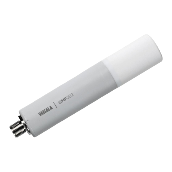
The probe is based on Vaisala’s patented 2nd generation CARBOCAPâ technology and equipped with Vaisala's Microglow infrared light source. The probe is easy to install with a plug-in/plug-out M12 connection. GMP252 is able to compensate for temperature, pressure and background gas. For temperature compensation purposes, the probe includes an internal temperature sensor that allows measurement compensation according to ambient temperature. -
Page 15: Basic Features And Options
‣ GMP252 specifications (page 109) 2.2.1 Connectivity to Vaisala Insight software The probe can be connected to Vaisala Insight software using a Vaisala USB cable (item code 242659) or Vaisala Indigo USB adapter (item code USB2). With the Insight software, you can: •... -
Page 16: Additional Features With Indigo Transmitters
• Digital output or 3 analog outputs (depending on the transmitter model) • 2 configurable relays • USB-C connection to Vaisala Insight PC software for easy configuration access Available features vary depending on the Indigo transmitter model. For more information on Indigo transmitters, see www.vaisala.com/indigo. -
Page 17: Filter Options
Chapter 2 – Product overview 2.2.3 Filter options Figure 2 ASM212011SP flow-through adapter The GMP252 flow-through adapter (item code ASM212011SP) has two gas ports for controlled gas feed (port outer diameter 4.6 mm, port hole inner diameter 2 mm, suitable for tubing with 4 mm inner diameter). -
Page 18: Operating Principle Of Co Measurement
GMP252 User Guide M211897EN-E 2.3 Operating principle of CO measurement The Vaisala CARBOCAPâ sensor used in the probe is a silicon-based, nondispersive infrared (NDIR) sensor for measurement of gaseous carbon dioxide in air-like gases. Figure 3 Probe cuvette with mirror and sensor chips... -
Page 19: Environmental Compensation
Chapter 2 – Product overview Figure 4 CO measurement in the measurement cuvette Gold-plated mirror Light absorbed by CO in the measured gas Hermetic window Fabry-Pérot interferometer Light source (Microglow) Hermetic window Thermopile detector 2.4 Environmental compensation When necessary, various environmental compensations can be applied to improve the CO measurement accuracy of the probe. -
Page 20: Temperature Compensation
Compensation parameters are configured on the order form when ordering the probe, and can later be updated using Vaisala Industrial Protocol or Modbus protocol. You can also turn off any of the compensations. In that case, the probe uses the default compensation value that is mathematically neutral for the probe’s internal compensation... -
Page 21: Pressure Compensation
2.4.2 Pressure compensation The probe does not have on-board pressure measurement. However, a pressure reading from an external source can be used as a setpoint value for compensation using Vaisala Industrial Protocol or Modbus. If pressure compensation is turned off, the probe uses the default compensation value of 1013 hPa. -
Page 22: Analog Output Overrange Behavior
GMP252 User Guide M211897EN-E More information ‣ Configuring filtering factor with Insight (page 76) ‣ Example of configuring filtering factor with Indigo80 handheld indicator (page 82) ‣ Configuration registers (page 121) 2.7 Analog output overrange behavior The analog output of the probe has a defined behavior when the values measured by the probe are outside the scaled analog output range. -
Page 23: Analog Output Overrange Example
Chapter 2 – Product overview 2.7.1 Analog output overrange example Consider a probe with 0 ... 5 V output, scaled to 0 ... 2000 ppmCO • When the measured CO rises above 2000 ppmCO , the output rises above 5 V. •... -
Page 24: Safety
2.8.1 ESD protection Electrostatic Discharge (ESD) can cause immediate or latent damage to electronic circuits. Vaisala products are adequately protected against ESD for their intended use. However, it is possible to damage the product by delivering electrostatic discharges when touching an exposed contact on the product. -
Page 25: Installation
The GMP252 probe itself does not require a shielded cable, but if the installation environment contains high levels of EMC noise, the disturbance may be transmitted to another connected device through an unshielded cable. Vaisala Online Store at store.vaisala.com offers a wide selection of shielded cables in different lengths. -
Page 26: Installation Accessories
GMP252 User Guide M211897EN-E 3.3 Installation accessories The probe can be installed through a surface using the optional flange accessory (Vaisala product code 243261SP), or attached for example to a wall with the optional clip accessory (two-clip set, Vaisala product code 243257SP). -
Page 27: 243261Sp Mounting Flange
Chapter 3 – Installation 3.3.1 243261SP mounting flange The optional flange accessory is used to install Ø 25 mm (0.98 in) probes through a wall or other surface. Figure 7 Probe with 243261SP mounting flange 4 Phillips head screws (included) Mounting flange (diameter 60 mm (2.36 in)) with four Ø 4.2 mm (Ø 0.17 in) screw holes Gasket ring Leaving part of the probe body and the cable outside the measurement environment can cause heat conduction that affects the temperature... -
Page 28: 243257Sp Mounting Clips
GMP252 User Guide M211897EN-E 3.3.2 243257SP mounting clips The optional mounting clips (set of two clips) are used to hold the probe in place for example on a wall or other surface. Each clip base attaches to the installation surface with one screw (screw hole Ø... -
Page 29: Asm212017Sp Spray Shield
7. Place the top part on the base and tighten the hex screws with a 4-mm Allen key. 3.3.4 ASM212017SP spray shield The optional spray shield (Vaisala item code ASM212017SP) allows washing the probe with a pressure washer without exposing the sensor to moisture (IPX9 rating). -
Page 30: Dtr250 Radiation Shield
More information ‣ ASM212017SP spray shield dimensions (page 115) 3.3.5 DTR250 radiation shield The optional DTR250 radiation shield (Vaisala item code: DTR250) protects the probe from solar radiation and precipitation in outdoor installations. Figure 11 GMP252 in DTR250 radiation shield Mounting plate ø... -
Page 31: Gmp252 Probe Handle Accessories
3.3.7 GMP252 probe handle accessories Overview GMP252 probe handle accessories enable convenient portable use of Vaisala CARBOCAPâ Carbon Dioxide Probe GMP252, especially when using the probe with Vaisala Indigo80 Handheld Indicator. Probe handle accessory GMP252HANDLESP comes with a magnetic hanger, which enables attaching the probe to a metallic surface during, for example, logging of GMP252 measurement data. -
Page 32: Figure 13 Fastening Magnetic Hanger To Gmp252 Probe Handle
• Avoid depositing dirt on the probe filter if you need to touch it during removal Fastening magnetic hanger to GMP252 probe handle A magnetic hanger is available as an optional accessory from Vaisala (item code ASM214318SP). • 2-mm Allen key •... -
Page 33: Power Supply
Chapter 3 – Installation GMP252 probe handle specifications and dimensions 30 [1.2] 200 [8] Filter Ø M12×1 mm [in] Figure 14 GMP252 probe handle dimensions 3.4 Power supply The supply voltage range of the probe is 12 ... 30 V DC with the digital output option. If the analog output is used, the supply voltage range is 12 ... - Page 34 GMP252 User Guide M211897EN-E Pin# Function Note Cable 223263SP wire colors – Blue RS-485 + Current: Black or current 0 … 20 mA or 4 ... 20 mA (default analog output output scaling) Output control Connecting pin #5 to GND (pin #3) forces the probe Gray to analog output mode.
-
Page 35: Vaisala Industrial Protocol
4. Vaisala Industrial Protocol 4.1 Vaisala Industrial Protocol overview The RS-485 line of the probe provides an implementation of the Vaisala Industrial Protocol that can be used for service and configuration use, or for interfacing with the system to which the probe is integrated. The protocol is a plaintext protocol suitable for use both by human operators and automated systems. - Page 36 Windows and a USB computer connection cable. Connecting with a computer allows you to configure and troubleshoot your probe using serial line commands. 1. If you have not used the Vaisala USB cable before, install the driver before attempting to use the cable.
-
Page 37: Installing Driver For The Usb Service Cable
3. Locate the cable in the list of devices: • If the device is listed as Vaisala USB Device with a COM port number in brackets, the cable is ready for use. Note the COM port number, you will need it later. -
Page 38: Accessing Serial Commands From Modbus Or Analog Mode
Download the Vaisala USB driver at http://www.vaisala.com/software (select the appropriate USB Instrument Driver Setup for your cable). c. Extract the driver zip file and run the USB driver installation program Vaisala USB Device Driver Setup.exe. Accept the installation defaults. d. Go back to step 1 and verify that the driver installation works as expected. -
Page 39: Enabling Modbus Mode From Vaisala Industrial Protocol
Chapter 4 – Vaisala Industrial Protocol 4.6 Enabling Modbus mode from Vaisala Industrial Protocol If you need to switch from Vaisala Industrial Protocol to Modbus mode, you must configure the following settings: • Serial line operating mode • Modbus address • Serial line settings (bit rate, parity, stop and data bits) 1. -
Page 40: Serial Commands
GMP252 User Guide M211897EN-E 4.8 Serial commands The notation <cr> refers to the carriage return control character, which you can send in a terminal application by pressing enter on your keyboard. Before entering commands, send a <cr> to clear the command buffer. You can enter the commands in uppercase or lowercase. -
Page 41: Table 7 Advanced Serial Commands
Chapter 4 – Vaisala Industrial Protocol Command Description Environmental compensation Show or set environmental parameters. Adjustment information adate Show CO factory adjustment date. atext Show CO factory adjustment information. Other commands reset Reset the probe. pass [1300] Access advanced serial commands. -
Page 42: Device Information And Status
Show listing of device information even if device is in poll mode and connection has not been opened using the open command. Example: Device : GMP25x Copyright : Copyright (c) Vaisala Oyj 2016. All rights reserved. SW Name : GMP25x SW version : 1.0.0 SNUM : GMP233_5_18... -
Page 43: Table 11 Snum Command
Chapter 4 – Vaisala Industrial Protocol Syntax Description Example (showing a list of the basic commands): help ADATE ADDR ATEXT CLOSE ERRS FORM HELP INTV PASS ESET SDELAY SEND SENDX SERI SMODE SNUM SYSTEM UNIQID TIME VERS Table 11 snum command... -
Page 44: Serial Line Output And Communication
GMP252 User Guide M211897EN-E Table 13 time command Syntax Description time<cr> Show how long the probe has been in operation since the last startup or reset. The operation counter is in format hh:mm:ss. Example: time Time : 01:41:24 Table 14 vers command Syntax Description vers<cr>... -
Page 45: Table 16 Close Command
Chapter 4 – Vaisala Industrial Protocol Table 16 close command Syntax Description close<cr> Close the connection that was opened with the open command. Example: close line closed Table 17 form command Syntax Description form<cr> Show the currently used measurement format. form /<cr>... -
Page 46: Table 18 Output Parameters For Form Command
GMP252 User Guide M211897EN-E Syntax Description Example (set output format as CO ppm with Modulus-65536 checksum): form 6.0 "CO2=" CO2 " " U3 " " CS4 #r #n Output example (continuous output from RUN mode): CO2= 3563 ppm 9F CO2= 3562 ppm 9E CO2= 3559 ppm A4 Example (set output format as CO ppm, with start of text (ASCII character 002) and end of text... -
Page 47: Table 20 Intv Command
Chapter 4 – Vaisala Industrial Protocol Modifier Description Carriage-return. Line feed. "" String constant, length 1 ... 15 characters. #xxx ASCII code value (decimal) of a special character; for example, #027 for ESC. addr Probe address (0 ... 254). Probe serial number. -
Page 48: Table 21 Open Command
GMP252 User Guide M211897EN-E Syntax Description Example: intv 5 s Output interval: 5 S Table 21 open command Syntax Description open [aaa]<cr> Open a connection to a device at the specified address. Required when device is in poll mode. aaa = address, range 0 ... 254. Example (target probe in POLL mode, with address 52): open 52 GMP25x: 52 Opened for operator commands... -
Page 49: Table 24 Sdelay Command
Chapter 4 – Vaisala Industrial Protocol Syntax Description Example: CO2= 658 ppm CO2= 654 ppm CO2= 655 ppm Table 24 sdelay command Syntax Description sdelay<cr> Show serial line transmission delay (1 … 255). 1 unit = 4 milliseconds (for example, 5 = 0.020 second transmission delay). -
Page 50: Table 26 Seri Command
GMP252 User Guide M211897EN-E Table 26 seri command Syntax Description seri<cr> Show current serial line settings. seri [b p d s]<cr> Set new serial line settings. The new settings will be taken into use when the probe is reset or powered up. b = baud rate (9600, 19200, or 38400) p = parity •... -
Page 51: Analog Output
Chapter 4 – Vaisala Industrial Protocol Syntax Description smode [mode]<cr> Set serial line start-up operating mode. New mode is taken into use when the device is reset or powered up. Available modes: stop = No automatic output. All commands available. Default mode. -
Page 52: Table 29 Aover Command
GMP252 User Guide M211897EN-E Syntax Description amode [channel lo_value hi_value Set new analog output limits and error output error_value]<cr> value. channel = Analog output channel • 1 = voltage output (V) • 2 = current output (mA) lo_value = Low limit of the channel. hi_value = High limit of the channel. - Page 53 Chapter 4 – Vaisala Industrial Protocol Syntax Description aover [channel clipping error_ Set the behavior of the analog output when the limit]<cr> measured value is outside the scaled output range. channel = Analog output channel • 1 = voltage output (V) •...
- Page 54 GMP252 User Guide M211897EN-E Syntax Description Example (for channel 1): 1. View currently set analog output scaling (asel command), limits and error level (amode command), and overrange behavior (aover command): pass 1300 asel 1 Aout 1 quantity : CO2(0 ... 2000) amode 1 Aout 1 range (V) : 0.00 ...
-
Page 55: Figure 15 Example Of Analog Output Overrange Behavior
Chapter 4 – Vaisala Industrial Protocol Syntax Description Output voltage (V) Error level 0.00 Output clipping limit 5.25 5.00 In error state at >2200 ppm (2000 ppm + 10%) Clipped at 2100 ppm (2000 ppm + 5%) Regular measurement Time Figure 15 Example of analog output overrange behavior... -
Page 56: Calibration And Adjustment Commands
GMP252 User Guide M211897EN-E Syntax Description asel [channel] [parameter lowlimit Set the parameter and scaling of the analog highlimit]<cr> output. channel = Analog output channel parameter = Parameter that is output on analog channel. The only parameter available is (in ppm). lowlimit = Lower limit of channel scaling in ppm. -
Page 57: Table 32 Atext Command
Chapter 4 – Vaisala Industrial Protocol Table 32 atext command Syntax Description atext<cr> Show CO factory adjustment information. Example: atext Adjusted at Vaisala/Helsinki Table 33 cdate command Syntax Description cdate<cr> Show calibration date. cdate [yyyymmdd]<cr> Set a new calibration date. yyyymmdd = Year (yyyy), month (mm) and day... -
Page 58: Table 35 Cco2 Command
GMP252 User Guide M211897EN-E Syntax Description Example (set a new information text): ctext 0/1000 by NN Calibrated at 0/1000 ppm by NN Table 35 cco2 command Syntax Description cco2<cr> Show current user adjustment status. cco2 -lo [co2]<cr> Perform a 1-point (only either low or high concentration) or 2-point (both low and high cco2 -hi [co2]<cr>... - Page 59 Chapter 4 – Vaisala Industrial Protocol Syntax Description Example (perform a 1-point calibration): 1. Let the probe stabilize in the desired CO concentration (here: 500 ppmCO 2. Enter the calibration commands: pass 1300 cco2 -lo 500 cco2 -save 3. Enter a new calibration date and information text:...
-
Page 60: Environmental Compensation Commands
GMP252 User Guide M211897EN-E 4.13 Environmental compensation commands To apply an accurate relative humidity compensation, the temperature and pressure compensation configurations must also match your measurement environment. See the rhcmode, tcmode and pcmode commands for instructions on enabling compensation configuration, and env command for instructions on setting a compensation value. - Page 61 Chapter 4 – Vaisala Industrial Protocol Syntax Description env [xtemp | xpres | xoxy | xhum] Set new compensation values and store them in [value]<cr> RAM. RAM: n Volatile memory that loses the values when probe is reset, and where values are loaded from non-volatile memory at startup.
-
Page 62: Table 37 O2Cmode Command
GMP252 User Guide M211897EN-E Syntax Description Example (set temperature compensation to setpoint mode, and change temperature setpoint value to 5.00 °C in RAM): pass 1300 tcmode on T COMP MODE : ON env xtemp 5.00 In eeprom: Temperature (C) : 8.00 Pressure (hPa) : 1013.00 Oxygen (%O2) : 21.00 Humidity (%RH) : 30.000... -
Page 63: Table 38 Pcmode Command
Chapter 4 – Vaisala Industrial Protocol Table 38 pcmode command Syntax Description pcmode<cr> Check current pressure compensation mode. Possible modes: • on = Compensation enabled using setpoint value. • off = Compensation disabled, default (neutral) value used: see Environmental compensation (page 19). -
Page 64: Table 40 Tcmode Command
GMP252 User Guide M211897EN-E Syntax Description Example (check relative humidity compensation mode; relative humidity compensation is disabled, a neutral value is used): pass 1300 rhcmode RH COMP MODE : OFF Example (enable temperature, pressure and relative humidity compensation using setpoint values): pass 1300 tcmode on T COMP MODE : ON... -
Page 65: Other Commands
Chapter 4 – Vaisala Industrial Protocol 4.14 Other commands Table 41 frestore command Syntax Description frestore<cr> Restore the probe to its factory configuration. All user settings and user calibration parameters will be lost. After using the frestore command, reset the probe using the reset command. -
Page 66: Modbus
The probe can be accessed using the Modbus serial communication protocol. The supported Modbus variant is Modbus RTU (Serial Modbus) over RS-485 interface. For instructions on enabling the Modbus mode when you are using the probe with Vaisala Industrial Protocol, see Enabling Modbus mode from Vaisala Industrial Protocol (page 39). -
Page 67: Vaisala Insight Pc Software
• Calibrate and adjust the device. Download Insight at www.vaisala.com/insight. The probe can be connected to Vaisala Insight software using a Vaisala USB cable (item code 242659) or Vaisala Indigo USB adapter (item code USB2). GMP252 probes support Insight from probe software version 1.3.0 onwards. - Page 68 GMP252 User Guide M211897EN-E Connect the probe to Insight software in the exact order described in the following steps. 1. Open the Insight software on your PC. 2. Connect the USB cable to a free USB port on the PC. 3.
-
Page 69: Using Probe With Indigo200 Series Transmitters
RS-485 Modbus RTU and 2 programmable relays. Note that Indigo200 transmitters switched from a WLAN configuration interface to a USB-C cable configuration interface (Vaisala Insight PC software) in 2022. For instructions on configuring GMP252 probes with the earlier WLAN interface, see the earlier GMP252 User Guide revision M211897EN-E, available at docs.vaisala.com. -
Page 70: Connecting Probes
Probes are inserted into the probe connector with the orientation mark and/or the Vaisala logo facing out. 1. Insert the probe into the probe connector with the orientation mark and/or the Vaisala logo on the probe body facing out. Note the orientation of the cable connector pins when inserting. -
Page 71: Analog Output Configuration Overview
3. If no previous configuration exists (that is, this is the first time a probe is connected to the transmitter, and no configuration has been set manually), the transmitter adapts the analog output settings of the connected Vaisala Indigo-compatible probe automatically. If a configuration that differs from the connected probe's configuration exists in the transmitter, you must configure the new probe manually to enable the analog output. -
Page 72: Analog Output Configuration Example
GMP252 User Guide M211897EN-E Figure 20 Analog output type (current or voltage) selection in Insight Receiving analog output settings automatically from probe The transmitter can receive the analog output settings automatically from the connected probe in the following cases: 1. The transmitter is a new unit and has not been configured yet. 2. -
Page 73: Table 45 Indigo202 Modbus Registers
Chapter 7 – Using probe with Indigo200 series transmitters Table 45 Indigo202 Modbus registers Address Name Data type Probe registers (according to the connected probe's register map) 0000 First measurement probe address DFFF Last measurement probe address Indigo registers E000 Status 16-bit E001 Notification and error bits... -
Page 74: Default Communication Settings
GMP252 User Guide M211897EN-E 7.4.1 Default communication settings Figure 21 Insight PC software Communication menu view Modbus communication settings can be configured in the Insight PC software Configure device > Communication menu. Table 46 Default Modbus serial communication settings Description Default value Serial bit rate 19200 Parity None... -
Page 75: Figure 22 Relay Configuration Options (Co2 Probe Example)
Chapter 7 – Using probe with Indigo200 series transmitters Figure 22 Relay configuration options (CO2 probe example) Relay output on/off: Set to ON to enable relay output. Output parameter: The measurement that is used to control the relay. Options vary based on the type of the connected probe. -
Page 76: Configuring Filtering Factor With Insight
GMP252 User Guide M211897EN-E Relay state information When one or both relays are enabled, the relay state (active/not active) is shown on the transmitter display. You can also view the status of the relays with Insight PC software. Figure 23 Relay icons on display (relay A active, relay B not active) 7.6 Configuring filtering factor with Insight Figure 24 Filtering factor setting in Insight The filtering factor affects the speed at which the latest measurement is integrated into the... - Page 77 Chapter 7 – Using probe with Indigo200 series transmitters By default, the filtering factor is set to 1.0 (1.0 = 100 in the configuration range of the Insight user interface), which means the latest measurement is shown directly in the output, without any filtering.
-
Page 78: Using Probe With Indigo80 Handheld Indicator
8. Using probe with Indigo80 handheld indicator 8.1 Indigo80 handheld indicator Figure 25 Indigo80 handheld indicator Vaisala Indigo80 Handheld Indicator is a portable diagnostics tool that accommodates up to two Vaisala Indigo-compatible probes or transmitters for measuring a wide range of parameters. With the indicator, you can: •... -
Page 79: Probe Compatibility
Indigo80 menu for changing the settings of Indigo80 (for example, date, time, and language) and viewing device information. Help menu contains a Getting started tour showing the key features of Indigo80, as well as instructions for sending devices to Vaisala for calibration and maintenance. -
Page 80: Connecting Probes To Indigo80
8.2 Connecting probes to Indigo80 • Probe connection cable Up to two Vaisala Indigo-compatible probes or transmitters can be connected to the ports located on the bottom of Indigo80. You can connect and disconnect devices both when the indicator is powered on and when it is off. -
Page 81: Configuring Probe Features With Indigo80 Handheld Indicator
Chapter 8 – Using probe with Indigo80 handheld indicator 2. Insert the probe connection cable in one of the ports on the bottom of the indicator. • Note the orientation of the cable connector when inserting it • Hold the connector in place while turning its locking ring clockwise – never twist the connector body! 3. -
Page 82: Example Of Configuring Filtering Factor With Indigo80 Handheld Indicator
GMP252 User Guide M211897EN-E Accessing certain configuration options for your probe requires using the free Insight PC software, downloadable at www.vaisala.com/insight. 1. Connect the probe(s) to the indicator. 2. Open the main menu by pressing 3. Select Devices. If you have more than one device connected to the indicator, make a further selection between the devices. -
Page 83: Configuring Environment Settings With Indigo80 Handheld Indicator
Chapter 8 – Using probe with Indigo80 handheld indicator 8.4 Configuring environment settings with Indigo80 handheld indicator • Probe connection cable For optimal measurement accuracy, you can use the Indigo80 handheld indicator to give additional information about the connected probe’s measurement environment. The environment settings available via Indigo80 correspond to the environmental compensation settings of the probe. - Page 84 GMP252 User Guide M211897EN-E 6. Scroll down the Environment settings view and check that the compensation settings corresponding to the environment settings you defined in the previous steps are set to For example: • If you set a value for Pressure, make sure that Pressure compensation on/off is set to On as well.
-
Page 85: Operating With Mi70 Indicator
Chapter 9 – Operating with MI70 indicator 9. Operating with MI70 indicator 9.1 Overview of MI70 support The probe is compatible with instruments that utilize the MI70 indicator, for example the GM70 Handheld Carbon Dioxide Meter. The MI70 indicator is a convenient service tool for viewing the measurement readings and performing calibration and 1-point adjustment. -
Page 86: Graphical Display
2. If the MI70 indicator is on, turn it off. 3. Connect the probe to the MI70 indicator using the MI70 connection cable (Vaisala item code: CBL210472). 4. Turn on the MI70 indicator (time and date are requested at first startup). MI70 detects the probe and proceeds to show the measurement screen. -
Page 87: Mi70 Indicator Parts
Chapter 9 – Operating with MI70 indicator 9.6 MI70 indicator parts Figure 30 MI70 indicator parts Charger socket Function key shortcut buttons . The functions change according to what you are doing with the indicator. Arrow buttons: Move up in a menu Move down in a menu Enter a sub-menu Return to previous menu level... -
Page 88: Recording Data
GMP252 User Guide M211897EN-E 4. Select the saved display based on date and time by pressing the right arrow button. 9.8 Recording data With MI70, you can record transmitter measurement data over a certain period at chosen intervals. These recordings are saved in the MI70 memory and are available even after MI70 is disconnected from the transmitter. -
Page 89: Figure 32 Probe Compensation Settings On Mi70 Screen
Chapter 9 – Operating with MI70 indicator Figure 32 Probe compensation settings on MI70 screen When you turn a compensation off, the probe still shows a value for the corresponding display quantity (for example, Pcomp shows 1013.2 hPa). This is the default compensation value that is mathematically neutral for the probe’s internal compensation model. -
Page 90: Calibration And Adjustment
There are two easy ways to use a calibration gas as a reference: • You can supply the gas to the probe using the calibration adapter accessory (Vaisala item code DRW244827SP). Gas flow should be in the range 0.5 ... 1.1 l/min, recommendation is 1 l/min. -
Page 91: Effect Of Environmental Compensations
Available adjustment functions depend on the interface you use to operate the probe. If you want to integrate the functionality into a control system, the Modbus interface and the Vaisala industrial protocol are recommended. If you want to compare the reading of the probe to a reference instrument and adjust it accordingly, use the MI70 or the Indigo80 handheld indicator and a reference probe. - Page 92 GMP252 User Guide M211897EN-E Vaisala Industrial Protocol Vaisala industrial protocol supports 1-point and 2-point adjustment with the cco2 command. Configuration of the environmental compensation settings can be done using serial line commands. Modbus The environmental compensation settings can be configured using Modbus registers.
-
Page 93: Drw244827Sp Calibration Adapter
Chapter 10 – Calibration and adjustment 10.5 DRW244827SP calibration adapter The optional calibration adapter accessory can be used to feed a reference gas to the probe through a gas port when calibrating. Gas flow should be in the range 0.5 ... 1.1 l/min, recommendation is 1 l/min. -
Page 94: Overview Of Calibration With Indigo200 Using Insight
GMP252 User Guide M211897EN-E 10.6 Overview of calibration with Indigo200 using Insight Figure 34 Insight calibration menu main view (CO probe) The calibration menu in the Insight PC software contains options for calibrating and adjusting the measurement of the probe you have connected to the transmitter, and testing and adjusting the analog output channels of the transmitter. -
Page 95: Environmental Compensation
Chapter 10 – Calibration and adjustment Starting calibration To open the calibration menu, select to access Insight main menu. In the main menu, select Calibrate. Figure 35 Insight Calibrate menu selection Restoring factory adjustment Before adjusting the probe measurement, you can remove any possible earlier adjustments with the Restore factory adjustment selection, if needed. -
Page 96: Co 2 Probe Adjustment Example
GMP252 User Guide M211897EN-E The selection of environmental compensations available in the Indigo transmitter configuration menus depends on the features and configuration of the connected probe. If the probe you have connected to the transmitter supports environmental compensations, the configuration options are shown in the Configure device menu accessible from the Insight PC software main view. -
Page 97: Performing Manual Adjustment With Indigo80 Handheld Indicator
Chapter 10 – Calibration and adjustment 6. When the measurement has stabilized, click the Reference value, point 1 text box and enter the CO level of calibration point 1. Press ENTER or click outside the text box when done. 7. Check that the measured value for point 1 is automatically inserted. 8. -
Page 98: Restoring Factory Adjustment With Indigo80 Handheld Indicator
GMP252 User Guide M211897EN-E 6. Place the probe to the first reference point and select Reference value, point 1 to open the stabilizing graph view. Wait for the measurement to stabilize fully. The stabilization typically takes 5 … 15 minutes. Longer stabilization time results in more accurate calibration. -
Page 99: Calibration And Adjustment With Mi70 Indicator
Chapter 10 – Calibration and adjustment Always restore factory adjustment before entering a new adjustment. This prevents any possible earlier adjustments having an effect on the new adjustment you make. 1. Connect the probe(s) to the indicator. 2. Open the main menu by pressing 3. - Page 100 GMP252 User Guide M211897EN-E 3. If you are using the calibration adapter to feed a calibration gas to GMP252, you must feed the same gas to the reference probe as well. Refer to the documentation of your reference probe on how to do this and what accessories you need. 4.
-
Page 101: 1-Point Adjustment With A Reference Gas
10.9.2 1-point adjustment with a reference gas 1. Connect GMP252 to Port I of the MI70 indicator. 2. Feed a calibration gas to the GMP252 using the calibration adapter accessory (Vaisala item code: DRW244827SP). If you are using ambient air as the calibration gas, you must have a reference meter in the same environment to verify the CO concentration. - Page 102 GMP252 User Guide M211897EN-E 7. You may be prompted to check the environmental settings of the reference probe before proceeding. Press Yes to check the settings and Exit when you have checked and corrected the settings. 8. The adjustment mode is now active, and you can see the measured CO reading on the screen.
- Page 103 Chapter 10 – Calibration and adjustment 14. If the adjustment is successful, MI70 will show the text Adjustment Done, after which you will return to the adjustment mode. At this point you can press Back and Exit to leave the adjustment mode.
-
Page 104: Maintenance
GMP252 User Guide M211897EN-E 11. Maintenance 11.1 Cleaning You can clean the probe body by wiping it with a moist cloth. Standard cleaning agents can be used. When cleaning, follow these precautions: • Do not immerse the probe in liquid to clean it. •... -
Page 105: Changing The Filter
Chapter 11 – Maintenance 11.2 Changing the filter Change the filter to a new one if it shows visible signs of contamination or dirt. When changing the filter, use clean gloves to avoid blocking the pores of the new filter. Figure 38 Opening the filter CAUTION! When changing the filter, you can use clean instrument air to gently blow any loose dirt and filter material from the sensor. -
Page 106: Troubleshooting
GMP252 User Guide M211897EN-E 12. Troubleshooting 12.1 Problem situations Problem Possible cause Remedy Analog output reading is Analog output is in error state. Remove the cause of the error unchanging and appears state and the analog output will incorrect. recover its normal function. Probe outputs stars "****"... - Page 107 Chapter 12 – Troubleshooting • Status indicates a known state of the unit. In case of constant error, contact Vaisala. If using the probe in Modbus mode, see the possible error messages in Table 59 (page 124). Error message and code...
-
Page 108: Analog Output Error State
GMP252 User Guide M211897EN-E Error message and code Description Recommended action Cut warning [23] EMC interference error limit Check for EMC interference approaching. sources. Unexpected restart Transmitter is reset by Continue normally. detected [24] watchdog process. Status messages adjustment mode Complete the CO adjustment. -
Page 109: Technical Data
Chapter 13 – Technical data 13. Technical data 13.1 GMP252 specifications Table 47 GMP252 measurement performance Property Description/value Measurement range 0 … 10 000 ppm CO (up to 30 000 ppm CO with reduced accuracy) Accuracy 0 … 3000 ppm CO ±40 ppm CO 3000 …... -
Page 110: Table 48 Gmp252 Operating Environment
GMP252 User Guide M211897EN-E Property Description/value dependence With compensation, 0 … 10 000 ppm %CO ±0.6 % of reading (at +25 °C (+77 °F)) 0 … 90 %O Without compensation (typical) −0.08 % of reading/%O Start-up, warm-up, and response time Start-up time at +25 °C <... -
Page 111: Table 49 Gmp252 Inputs And Outputs
• 0 … 5/10 V (scalable), min. load 10 kΩ • 0/4 … 20 mA (scalable), max. load 500 Ω Digital output Over RS-485: • Modbus • Vaisala Industrial Protocol Operating voltage With digital output in use 12 … 30 V DC With voltage output in use 12 …... -
Page 112: Spare Parts And Accessories
Compliance marks CE, RCM 13.2 Spare parts and accessories Information on spare parts, accessories, and calibration products is available online at www.vaisala.com and store.vaisala.com. Table 52 GMP252 spare parts and accessories Item Item code Porous sintered PTFE filter for GMP252 DRW244221SP Probe connection cable with open wires (1.5 m), shielded 223263SP Probe connection cable with open wires (1.5 m), shielded... -
Page 113: Gmp252 Probe Dimensions
Calibration adapter DRW244827SP Spray shield ASM212017SP Radiation shield DTR250 DTR250 Radiation shield DTR250 with pole mounting kit DTR250A Vaisala Insight software for Windows is available at www.vaisala.com/insight. 13.3 GMP252 probe dimensions 130 [5.12] [0.47] 75 [2.95] 42 [1.65] M12 male connector... -
Page 114: 243261Sp Mounting Flange Dimensions
GMP252 User Guide M211897EN-E 13.4 243261SP mounting flange dimensions 36 [1.41] mm [in] Figure 40 243261SP mounting flange dimensions Ø 60 [2.36] Ø 36 [1.41] Ø 25.6 [1.008] Ø 28.5 [1.12] mm [in] Ø 42 [1.65] Figure 41 243261SP mounting flange dimensions, cross section... -
Page 115: Drw244827Sp Calibration Adapter Dimensions
Chapter 13 – Technical data 13.5 DRW244827SP calibration adapter dimensions Figure 42 DRW244827SP calibration adapter dimensions 13.6 ASM212017SP spray shield dimensions 72 [2.83] Ø 40 [1.57] Shield + GMP251: 113 [4.45] [in] Shield + GMP252: 146 [5.75] Figure 43 ASM212017SP spray shield dimensions... -
Page 116: Figure 44 Gmp252 Spray Shield Cross Section
GMP252 User Guide M211897EN-E Figure 44 GMP252 spray shield cross section... -
Page 117: Dtr250 Radiation Shield Dimensions
Chapter 13 – Technical data 13.7 DTR250 radiation shield dimensions Figure 45 DTR250 radiation shield 105 [4.13] dimensions (mm) [in]... -
Page 118: Dtr250A Pole Mounting Kit Dimensions
GMP252 User Guide M211897EN-E 13.8 DTR250A pole mounting kit dimensions 105 [4.13] 213 [8.38] [in] Figure 46 DTR250A pole mounting kit dimensions (in mm [inch]) -
Page 119: Appendix A: Modbus Reference
Appendix A – Modbus reference Appendix A. Modbus reference A.1 Default communication settings Table 53 Default Modbus serial communication settings Property Description/Value Serial bit rate 19200 Parity Number of data bits Number of stop bits Modbus device address A.2 Function codes Table 54 Modbus function codes Function code (decimal) Function code (hexadecimal) Name... -
Page 120: 16-Bit Integer Format
GMP252 User Guide M211897EN-E Despite the specification, some Modbus masters may expect a "big-endian" word order (most significant word first). In such case, you must select "word-swapped" floating point format in your Modbus master for the Modbus registers of the device. A complete 32-bit floating point or 32-bit integer value should be read and written in a single Modbus transaction. -
Page 121: Measurement Data Registers
Appendix A – Modbus reference A.4.1 Measurement data registers Table 56 Modbus measurement data registers (read-only) Register Address Description Data format Unit number 0000 Measured CO value 32-bit float 0002 Compensation T 32-bit float °C 0004 Measured T 32-bit float °C 0100 Measured CO value 16-bit signed integer ppm (up to 32 000 ppm) 0101... - Page 122 GMP252 User Guide M211897EN-E Register Address Description Data Unit / Valid range number format 0206 Power-up value for 32-bit float oxygen compensation 0 ... 100 % (Init/default: 0) 0208 Volatile (value cleared 32-bit float Range 500 ... 1100 hPa at probe reset) pressure (Init copied from power-up value) compensation 020A...
-
Page 123: Status Registers
Appendix A – Modbus reference Register Address Description Data Unit / Valid range number format 0305 Temperature enum 0 = Off compensation mode 1 = Given 2 = Measured (default: 2 (Measured)) 0306 Humidity compensation enum 0 = Off mode 1 = On (default: 0 (Off)) 0307... -
Page 124: Table 59 Error Codes In Register 0803
GMP252 User Guide M211897EN-E Register Address Description Data format Notes number 2052 0803 Error code 32-bit field See table Error codes in register 0803 below. Table 59 Error codes in register 0803 Bitmask Error message Severity 0000 Status OK. 0001 Program memory crc critical error. Critical 0002 Parameter memory crc critical error. -
Page 125: Device Identification Objects
"2020-01-31" CalibrationDate Calibration date in YYYY-MM-DD format. Empty string if not set/valid. "Vaisala/HEL" CalibrationText Calibration information text. Empty string if not set/valid. Vaisala-specific device information. A.6 Exception responses Table 61 Modbus exception responses Code Name Reason ILLEGAL FUNCTION Unsupported function code ILLEGAL DATA ADDRESS Register address or Object ID out of valid ranges... -
Page 126: Modbus Communication Examples
GMP252 User Guide M211897EN-E A.7 Modbus communication examples Reading CO value Device address used in the following examples is 240 (F0 The values returned by the device differ depending on the ambient conditions and/or device settings. Your device might not return exactly same values. Request Response Bytes on the line... - Page 127 Appendix A – Modbus reference Writing volatile compensation pressure value Request Response Bytes on the line Description Bytes on the line Description (hexadecimal) (hexadecimal) (silence for 3.5 bytes) Start of Modbus RTU (silence for 3.5 bytes) Start of Modbus RTU frame frame GMP25x address...
-
Page 128: Filtering Factor
GMP252 User Guide M211897EN-E Communication description Data format Two 16-bit Modbus registers interpreted as IEEE 754 binary32 floating point value, least significant word first. Value to write 1013.25 (hPa), in binary32 format 447D5000 A.8 Filtering factor Modbus register 777 sets the CO filtering factor. - Page 129 Please see the applicable supply contract or Conditions of Sale for details of the warranty for each product. Technical support Contact Vaisala technical support at helpdesk@vaisala.com. Provide at least the following supporting information as applicable: • Product name, model, and serial number •...
- Page 132 www. v aisala.com...
Need help?
Do you have a question about the CARBOCAP GMP252 and is the answer not in the manual?
Questions and answers