Table of Contents
Advertisement
Quick Links
Advertisement
Table of Contents

Related Manuals for Vaisala GMP231


Summary of Contents for Vaisala GMP231
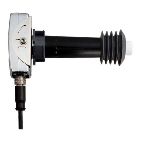
- Page 1 M211501EN-E User Guide Carbon dioxide probe for CO incubators GMP231...
- Page 2 English versions are This product contains software developed applicable, not the translations. by Vaisala or third parties. Use of the The contents of this document are subject software is governed by license terms and to change without prior notice.
- Page 3 Probe installation depth................. 17 Dimensions....................... 18 Recommended installation................20 Wiring.......................22 Power supply....................23 Vaisala Industrial Protocol................ 24 Overview of Vaisala Industrial Protocol............24 Serial interface settings................. 24 Physical interface....................24 Connecting with a computer................ 24 4.4.1 Installing driver for the USB service cable........... 25 4.4.2...
- Page 4 6.4.4 Adjustment types ................... 73 Operating with MI70 indicator..............75 Overview of MI70 support................75 Connecting GMP231 to MI70 Indicator............75 Changing environmental compensation settings with MI70 indicator..75 Calibration and adjustment with MI70 indicator........77 7.4.1 1-point adjustment with an MI70-compatible reference probe..77 7.4.2...
- Page 5 Table of contents Online store.......................87 Warranty......................87 Technical support.................... 87 Recycling......................87...
-
Page 6: Table Of Contents
GMP231 User Guide M211501EN-E List of figures Figure 1 GMP231 installed through a chamber wall..........9 Figure 2 GMP231 parts.......................11 Figure 3 CARBOCAPâ sensor of the GMP231............12 Figure 4 measurement inside the incubator............13 Figure 5 Probe installation depth..................18 Figure 6 Probe dimensions without silicone plug............ - Page 7 List of tables Table Document versions (English)................7 Table 2 Related manuals....................7 Table 3 Applicable patents....................8 Table 4 GMP231 connector pinout................22 Table 5 Cable ........................23 Table 6 Default serial interface settings..............24 Table 7 Basic serial commands..................27 Table 8 Advanced serial commands................28...
- Page 8 Data formats...................... 64 Table 69 GMP231 register table..................64 Table 70 Possible problem situations and their remedies........81 Table 71 Measurement performance................83 Table 72 Operating environment...................84 Table 73 Inputs and outputs................... 84 Table 74 Mechanical specifications................85 Table 75 Spare parts and accessories for GMP231............85...
-
Page 9: Table Document Versions (English)
Chapter 1 – Commands 1. Commands 1.1 Version information This document provides information for installing, operating, and maintaining the Vaisala CARBOCAPâ Carbon Dioxide Probe GMP231. Table 1 Document versions (English) Document code Date Description M211501EN-E April 2020 • Corrected initial CRC calculation value in section Checksum (page 52) •... -
Page 10: Table 3 Applicable Patents
Indicates that you need to take some notes during the task. 1.4 Trademarks CARBOCAPâ is a registered trademark of Vaisala Oyj. All other product or company names that may be mentioned in this publication are trade names, trademarks, or registered trademarks of their respective owners. -
Page 11: Figure 1 Gmp231 Installed Through A Chamber Wall
GMP231 probe is based on patented Vaisala CARBOCAPâ technology and a new type of infra- red light source. The probe can remain in place during high-temperature sterilization cycles that heat the chamber interior to +180 °C. - Page 12 • Analog output: one current output channel (0 … 20 mA or 4 … 20 mA). • Digital output: • I • RS-485 (non-isolated) with Vaisala Industrial Protocol. More information ‣ Operating principle of CO2 measurement (page 12) ‣ Environmental compensation (page 13)
-
Page 13: Figure 2 Gmp231 Parts
Chapter 2 – Product overview 2.3 GMP231 parts Figure 2 GMP231 parts Electronics housing. Contains the main component board, including the digital pressure sensor. Holes for M4 screws on both sides of the housing. Maximum screw depth 8 mm. Two screws included, type BN 10649 M4. -
Page 14: Figure 3 Carbocapâ Sensor Of The Gmp231
2.4 Operating principle of CO measurement Vaisala CARBOCAPâ sensor used in the GMP231 is a silicon-based, non-dispersive infrared (NDIR) sensor for the measurement of gaseous carbon dioxide. It is especially designed to tolerate high temperatures in standby mode, up to +195 °C (+383 °F). This allows it to be used in applications that utilize high temperature for heat sterilization. -
Page 15: Figure 4 Co 2 Measurement Inside The Incubator
Gold-plated mirror 2.5 Environmental compensation GMP231 improves the CO measurement accuracy by applying various environmental compensations. GMP231 compensates for the effects of: • Pressure • Temperature • Background gas oxygen (O ) content • Background gas relative humidity (%RH) - Page 16 GMP231 User Guide M211501EN-E You can also turn off any of the compensations. In that case, GMP231 uses the default compensation value that is mathematically neutral for the probe’s internal compensation model. For more information on the effect of the compensations on measurement accuracy, see GMP231 specifications (page 83).
- Page 17 • Output resumes normal function when measured value returns to within 10% of the selected range. For example, consider a GMP231 with 0 ... 20 mA analog output, scaled to 0 ... 10 %CO • When measured CO rises above 10 %CO , the output rises above 20 mA.
- Page 18 2.8.1 ESD protection Electrostatic Discharge (ESD) can damage electronic circuits. Vaisala products are adequately protected against ESD for their intended use. However, it is possible to damage the product by delivering electrostatic discharges when touching, removing, or inserting any objects in the equipment housing.
- Page 19 3.3 Probe installation depth GMP231 must be installed so that only the sensor element and the filter are inside the chamber. If the probe is longer than the installation tube, the extra length should extend to the outside of the chamber.
-
Page 20: Figure 5 Probe Installation Depth
GMP231 User Guide M211501EN-E 2.5 mm Figure 5 Probe installation depth 3.4 Dimensions 118.5 Screw BN 10649 M4 x 8 mm Position only the filter (for 1 mm thick sheet metal inside the heated chamber attachment) Figure 6 Probe dimensions without silicone plug... -
Page 21: Figure 7 Probe Dimensions With Silicone Plug
Chapter 3 – Installation 118.5 Recommended diameter for installation tube 44 mm Screw BN 10649 M4 x 8 mm Position only the filter (for 1 mm thick sheet metal inside the heated chamber attachment) Incubator’s inner wall Figure 7 Probe dimensions with silicone plug 54.4 Reserve space for M12 cable Figure 8 Electronics housing dimensions... -
Page 22: Figure 9 Attachment Bracket Dimensions
Figure 9 Attachment bracket dimensions 3.5 Recommended installation GMP231 is designed to be installed through a chamber wall, and attached to the chamber chassis using an attachment bracket and the two screw holes on the side of the probe. As the installation depth of the probe inside the chamber is critical, the mounting method must allow the probe to be positioned exactly. -
Page 23: Figure 10 Recommended Installation
Chapter 3 – Installation Figure 10 Recommended installation Ambient air Chamber wall Chamber interior GMP231 electronics housing M4 screw holes on both sides of the probe housing 8-pin M12 connector Cable CARBOCAPâ sensor under PTFE filter. The filter must be inside the chamber completely. -
Page 24: Table 4 Gmp231 Connector Pinout
M211501EN-E 3.6 Wiring GMP231 provides several outputs you can use. Connect the output pins you need, and the power supply and ground pins. Use a shielded cable, and connect the shield to the chassis of the GMP231’s M12 connector, and to ground on the other side. -
Page 25: Table 5 Cable
Power supply + Blue Ground Shield Black 3.7 Power supply The supply voltage range of GMP231 is 11 … 30 VDC. If the analog output is used, the supply voltage range is 20 … 30 VDC. The maximum power consumption is 1 W. -
Page 26: Table 6 Default Serial Interface Settings
4. Vaisala Industrial Protocol 4.1 Overview of Vaisala Industrial Protocol RS-485 line of the GMP231 provides an implementation of the Vaisala Industrial Protocol that can be used for service and configuration use, or for interfacing with the incubator’s control system. The protocol is a plaintext protocol suitable for use both by human operators and automated systems. - Page 27 3. Locate the cable in the list of devices: • If the device is listed as Vaisala USB Device with a COM port number in brackets, the cable is ready for use. Note the COM port number, you will need it later.
- Page 28 3. Select Connection > Serial & USB and check that the correct COM port is selected in the Serial or USB line to connect to field. If you are using the PuTTY terminal application supplied by Vaisala, you can press the USB Finder button to open the Vaisala USB Instrument Finder program.
-
Page 29: Figure 11 Putty Terminal Application
Chapter 4 – Vaisala Industrial Protocol 6. You may need to adjust the Local echo setting in the Terminal category to see what you are typing on the serial line. To access the configuration screen while a session is running, click the right mouse button over the session window, and select Change Settings from the pop-up menu. -
Page 30: Table 8 Advanced Serial Commands
GMP231 User Guide M211501EN-E Command Description ERRS Show currently active errors. FORM [modifier string] Show or set output format. HELP Show list of currently available serial commands. INTV [0 ... 9999 s/min/h] Set continuous output interval for R command. OPEN [address]... -
Page 31: Table 10 Snum Command
Do not use the ?? command if you have more than one device on an RS-485 line. Example: Device : GMP231 Copyright : Copyright (c) Vaisala Oyj 2013. All rights reserved. SW Name : GMP231 SW version : 1.0.1.1537 Snum... -
Page 32: Table 11 Vers Command
GMP231 User Guide M211501EN-E Table 11 VERS command Syntax Description VERS Show firmware version of the probe. Example: vers GMP231 / 1.1.0.1537 Table 12 SYSTEM command Syntax Description SYSTEM<cr> Show probe firmware information. Example: system Device Name : GMP231 SW Name : GMP231 SW version : 1.1.0.1537... -
Page 33: Table 15 R Command
Chapter 4 – Vaisala Industrial Protocol Syntax Description Example (shows basic commands, advanced commands are not enabled): CLOSE ECHO ERRS FORM HELP INTV PASS RESET SDELAY SEND SERI SMODE SNUM STANDBY SYSTEM TIME VERS 4.7 Serial line output commands Table 15 R command... -
Page 34: Table 16 S Command
GMP231 User Guide M211501EN-E Table 16 S command Syntax Description S<cr> Stop the continuous outputting that was started with the R command. Example: CO2= 5.1 %CO2 CO2= 5.0 %CO2 CO2= 5.0 %CO2 Table 17 INTV command Syntax Description INTV [n xxx]<cr> Change the output interval of the automatically repeating measurement messages. -
Page 35: Table 19 Form Command
Chapter 4 – Vaisala Industrial Protocol Table 19 FORM command Syntax Description FORM<cr> Change the measurement message sent by the probe. FORM /<cr> Reset measurement format to default. FORM [modifier string]<cr> modifier string = String of parameters and modifiers that defines the output format, length 1 ... -
Page 36: Table 20 Output Commands For Form Command
GMP231 User Guide M211501EN-E Syntax Description Examples: Example of default output (continuous output from RUN mode): CO2= 860 ppm CO2= 861 ppm CO2= 861 ppm Command to set output format as %CO form 3.1 "CO2=" CO2% " " U4 #r #n... -
Page 37: Table 21 Modifiers For Form Command
Chapter 4 – Vaisala Industrial Protocol Measured parameter Abbreviation in FORM command CO2% Carbon dioxide in percent TCOMP Currently used temperature compensation value PCOMP Currently used pressure compensation value O2COMP Currently used oxygen concentration compensation value RHCOMP Currently used relative humidity compensation value Table 21 Modifiers for FORM command... -
Page 38: Table 23 Env Command
GMP231 User Guide M211501EN-E Syntax Description TCMODE [on | off | measured]<cr> Show current compensation value for temperature compensation mode. O2CMODE [on | off]<cr> Show current compensation value for oxygen compensation mode. RHCMODE [on | off]<cr> Show current compensation value for relative humidity compensation mode. - Page 39 Chapter 4 – Vaisala Industrial Protocol Syntax Description ENV [xtemp|xpres|xoxy|xhum] Set new compensation values and store them in [value]<cr> RAM. • xtemp = Compensation temperature. Range -40 ... 100 °C. • xpres = Compensation pressure. Range 500 ... 1150 hPa.
-
Page 40: Table 24 Standby Command
GMP231 User Guide M211501EN-E If temperature and pressure compensations are configured to use internally measured values, they continuously update the values in RAM, overriding any temperature and pressure values that are written to RAM with the ENV command. Table 24 STANDBY command... -
Page 41: Table 26 Seri Command
Chapter 4 – Vaisala Industrial Protocol Table 26 SERI command Syntax Description SERI<cr> Show current serial line settings. SERI [b p d s]<cr> Set new serial line settings. The new settings are taken into use when the probe is reset or powered up. -
Page 42: Table 28 Sdelay Command
: OFF 4.10 Calibration commands Before calibrating GMP231 using serial line commands, see Calibration and adjustment (page 71). Make sure that the environmental compensation settings of the GMP231 are properly set for your calibration environment. Table 30 CCO2 command Syntax Description cco2<cr>... -
Page 43: Table 31 Cdate Command
Chapter 4 – Vaisala Industrial Protocol Syntax Description cco2 -save<cr> Save the currently entered adjustments. Successfully saving the adjustment clears the calibration date (cdate command) and calibration text (ctext command) that have been stored in the probe. Use those commands to enter a new calibration date and text. -
Page 44: Table 32 Ctext Command
GMP231 User Guide M211501EN-E Syntax Description Example (show currently stored calibration date): >pass 1300 >cdate Calibration date 2013-10-03 Example (set calibration date to 2014-03-10): >pass 1300 >cdate 2014 03 10 Calibration date 2014-03-10 Table 32 CTEXT command Syntax Description CTEXT<cr> Show calibration information text. -
Page 45: Table 34 Cp Command
Chapter 4 – Vaisala Industrial Protocol Syntax Description Example (adjust the internal temperature measurement to 23 °C at the current conditions): pass 1300 ct 23 Example (clear the offset adjustment from internal temperature measurement): pass 1300 ct -reset Table 34 CP command... -
Page 46: Table 35 Asel Command
GMP231 User Guide M211501EN-E 4.11 Configuring analog output Table 35 ASEL command Syntax Description ASEL [channel]<cr> Show the parameter and scaling of the analog output in ppm. channel = Analog output channel, only 1 can be selected. ASEL [channel] [parameter lowlimit Set the parameter and scaling of the analog highlimit]<cr>... -
Page 47: Table 37 Aover Command
Chapter 4 – Vaisala Industrial Protocol Syntax Description Example (show current configuration): pass 1300 amode 1 Aout 1 range (mA) :4.00 ... 20.00 (error :21.00) Example (set channel to 4 … 20 mA, and error level to 3.6 mA): pass 1300 amode 1 4 20 3.6... -
Page 48: Table 38 Atest Command
GMP231 User Guide M211501EN-E Syntax Description For example, first check the analog output settings using ASEL, AMODE, and AOVER commands: pass 1300 asel 1 Aout 1 quantity : CO2(0 ... 50000) amode 1 Aout 1 range (mA) :0.00 ... 20.00 (error : 23) -
Page 49: Table 39 Pass Command
Chapter 4 – Vaisala Industrial Protocol Syntax Description Example (enable analog output test mode, set level to 20 mA): pass 1300 atest 1 20 Aout 1 (mA) :20.000 Example (disabling analog output test mode, resuming normal output): atest 1 Aout 1 test mode disabled. -
Page 50: Table 42 Errs Command
GMP231 User Guide M211501EN-E Syntax Description Example (target probe in POLL mode, with address 52): Example: close line closed Table 42 ERRS command Syntax Description ERRS<cr> Show active errors. The possible errors and their identifying numbers correspond to content of the status word of the I C interface. -
Page 51: Table 44 Frestore Command
Chapter 4 – Vaisala Industrial Protocol Table 44 FRESTORE command Syntax Description FRESTORE<cr> Restore the probe to its factory configuration. All user settings are lost. After using the FRESTORE command, reset the probe using the RESET command. Example: pass 1300 frestore... -
Page 52: Figure 12 Hardware Schematic
More information ‣ Wiring (page 22) 5.1.2 Communication parameters GMP231 supports maximum 50 kHz clock speed. Protocol bits are sent most significant bit (MSB) first. Parameter bytes are sent using little endian order. 5.1.3 Addressing GMP231 uses 7-bit addressing. The address consists of: •... -
Page 53: Table 45 Gmp231 I 2 C Address
Sub-address Read/write bit (LSB) The I C implementation of the GMP231 also includes the address inside the message frame. The purpose of this is to make the I C implementation easier, since the I C address can be lost by the I C hardware. -
Page 54: Table 48 Status Byte
5.1.7 Status word The status word is used to monitor the status of the GMP231 device. It can be read in the same way as any other slave parameter. The status word is used as a 32-bit long bit field, where each bit represents a state of some error or other essential status. -
Page 55: Table 49 Status Word Content
After using the instructions in the following table and in Problem situations (page 81), try to power cycle the probe and see if the error stays on. If your unit has persistent errors that you cannot resolve yourself, contact Vaisala. Table 49 Status word content Bit# Type... -
Page 56: Table 50 Get_Interface_Version Invoke Message
GMP231 User Guide M211501EN-E Bit# Type Meaning Recommended action Error Low IR current. Reserved Warning Low input signal. Can be caused by dirt Continue normally. or condensation on the optical surfaces. Reserved Warning Noisy signal. Continue normally. Warning Transmitter reset by watchdog process. -
Page 57: Table 51 Get_Interface_Version Response Message
Chapter 5 – I2C interface Message segment Length Content Frame length 1 byte Always 05 Checksum 2 bytes Checksum (page 52). Table 51 Get_Interface_Version response message Message segment Length Content 1 byte C address C address (read) Status 1 byte Status byte (page 51). -
Page 58: Table 53 Get_Parameter Response Message
GMP231 User Guide M211501EN-E Table 53 Get_Parameter response message Message segment Length Content 1 byte C address C address (read) Status 1 byte Status byte (page 51). If requested parameter ID was unknown, NACK bit is set in the status byte. -
Page 59: Table 55 Set_Parameter Invoke Message
Set_Parameter command (ID 82 ) writes parameter values to non-volatile memory. You can use it to set the operational parameters of the GMP231. Depending on the change, the functionality of the GMP231 may not change immediately. The length of the invoke message varies depending on the data length. The master must write as many bytes as indicated in the frame length of the invoke message. -
Page 60: Table 56 Set_Parameter Response Message
GMP231 User Guide M211501EN-E Table 56 Set_Parameter response message Message segment Length Content 1 byte C address C address (read) Status 1 byte Status byte (page 51). Command ID 1 byte Always 82 Device address 1 byte Table 46 (page 51). -
Page 61: Table 58 Set Compensation Temperature Sequence Example
) reads the properties of a single parameter from the GMP231. The command is useful for adapting to parameters that have been added in a new software version. If the requested parameter ID is not valid, data type Unknown Parameter ID... -
Page 62: Table 59 Get_Parameter_Info Invoke Message
GMP231 User Guide M211501EN-E Table 59 Get_Parameter_Info invoke message Message segment Length Content 1 byte C address C address (write) Command ID 1 byte Always 83 Device address 1 byte Table 46 (page 51). Frame length 1 byte Always 06 Data... -
Page 63: Table 62 Parameter Persistence
Chapter 5 – I2C interface Code Meaning Float (32-bit) String Table 62 Parameter persistence Code Meaning Void Volatile Non volatile 5.2.5 Adjust Adjust command (ID 84 ) controls the user adjustment sequence of CO measurement. Table 63 Adjust invoke message Message segment Length Content 1 byte C address... -
Page 64: Table 65 Adjustment Subcommands
GMP231 User Guide M211501EN-E Message Segment Length Content Frame length 1 byte Always 07 Data 1 byte Return code. See Table 67 (page 62). Checksum 2 bytes Checksum (page 52). Table 65 Adjustment subcommands Code Adjustment operation Start 1 point adjustment... - Page 65 Chapter 5 – I2C interface 5.3 Adjusting measurement Before implementing an adjustment sequence using the Adjust command, read the general instructions for calibration and adjustment. Create the reference environment inside the chamber, and use the Adjust command to perform the adjustment sequence. Adjustment can fail for a number of reasons.
-
Page 66: Table 68 Data Formats
Maximum string size refers to maximum communication buffer size. For the actual reserved storage space for each parameter, see Register table (page 64). Integers and floating point numbers are sent LSB first. 5.4.2 Register table Table 69 GMP231 register table Meaning Name Size in Type Read/... - Page 67 Chapter 5 – I2C interface Meaning Name Size in Type Read/ Persistent Other bytes write Sensor number SSNUM Example: B1234567 Component CBNUM Example: board number C1234567 Software version VERS Example: number 1.2.3.4567 Factory ADATEY Uint Example: 2014 adjustment date Year Factory ADATEM Byte...
- Page 68 GMP231 User Guide M211501EN-E Meaning Name Size in Type Read/ Persistent Other bytes write Sensor heating HEAT Byte Range 0…1 0 = no heating 1 = heating (default) Compensation settings Temperature TC_MODE Byte compensation Compensation mode 1 = Use temperature...
- Page 69 Chapter 5 – I2C interface Meaning Name Size in Type Read/ Persistent Other bytes write Oxygen O2C_MODE Byte compensation Compensation mode 1 = Use oxygen concentration setpoint value (default) Compensation O2_COMP Float R/W oxygen Adjustment settings Reference CO CO2_RP1 Float R/W ppm CO point 1 Measured CO...
- Page 70 GMP231 User Guide M211501EN-E Meaning Name Size in Type Read/ Persistent Other bytes write Analog output A_EC Float R/W 0 … 25 mA error state current Analog output A_LC Byte 0 = 0 mA low end current 1 = 4 mA...
- Page 71 The CARBOCAPâ sensor of the GMP231 is well protected by the PTFE filter, and it can tolerate some dirt on the optics as the measurement is compensated for the reduction of signal.
-
Page 72: Figure 13 Changing The Filter
GMP231 User Guide M211501EN-E 3. Take a new clean filter and push it onto the sensor. If you are using the Vaisala silicone plug for sealing, push and rotate the filter slightly to make sure the filter reaches below the edge of the plug. -
Page 73: Figure 14 Changing The Silicone Plug
Correcting the reading of the GMP231 so that is measures accurately is referred to as adjustment. 6.4.1 Calibration setup GMP231 is designed to be calibrated while it remains installed through an incubator wall. If you calibrate the GMP231 without it being installed, note the following:... -
Page 74: Figure 15 Inserting The Calibration Adapter Over The Filter
There are 2 easy ways to use a calibration gas as a reference: • You can supply the gas to the GMP231 using the calibration adapter accessory. Gas flow should be in the range 0.5 … 1.1 l/min, recommendation is 1 l/min. Allow the measurement to stabilize for three minutes before starting the calibration. - Page 75 0 ppm CO reference. • Remember to restore the normal compensation settings after completing calibration and adjustment. If you are integrating the calibration functionality of the GMP231 as part of the incubator’s control software, also implement proper handling of the environmental compensations.
- Page 76 • 2-point adjustment is recommended if you typically measure a variable CO level. Available adjustment functions depend on the interface you use to operate the GMP231. If you want to integrate the functionality into the incubator’s control system, the I C interface and the Vaisala Industrial Protocol are recommended.
-
Page 77: Figure 16 Co 2 Reading On Mi70 Screen
MI70 screen 7.2 Connecting GMP231 to MI70 Indicator 1. If GMP231 is installed in an incubator, disconnect the incubator’s cable from the 8-pin M12 connector. Note that GMP231 can remain physically connected to the incubator. 2. If the MI70 indicator is on, turn it off. -
Page 78: Figure 17 Co2 Reading With Tcomp And Pcomp On Mi70 Screen
Figure 18 GMP231 compensation settings on MI70 screen When you turn a compensation off, GMP231 still shows a value for the corresponding display quantity (for example, Pcomp shows 1013.2 hPa). This is the default compensation value that is mathematically neutral for the probe’s internal compensation model. - Page 79 2. Connect the calibrated reference probe to Port II. Make sure the reference probe is in the same environment as the GMP231’s sensor. 3. If you are using the calibration adapter to feed a calibration gas to the GMP231, you must feed the same gas to the reference probe also. Refer to the documentation of your reference probe on how to do this, and what accessories you need.
- Page 80 GMP231 User Guide M211501EN-E 7. To proceed with the adjustment, select the CO2(I) parameter in the Select Quantity screen. In the Select Quantity screen you can also view the currently used compensation values, and the Last adjustment date information. You can update the date and text using the CDATE and CTEXT commands on the serial line.
- Page 81 1. Connect GMP231 to Port I of the MI70 indicator. 2. Feed a calibration gas to GMP231 using the calibration adapter accessory. If you are using ambient air as the calibration gas, you must have a reference meter in the same environment to verify the CO concentration.
- Page 82 GMP231 User Guide M211501EN-E 9. Select 1-point adjustment. 10. You are prompted if you really want to adjust. Select Yes. 11. You are now in the 1-point adjustment screen. Allow the measurement to stabilize and press Ready. 12. Enter the CO concentration of the reference gas and press OK.
-
Page 83: Table 70 Possible Problem Situations And Their Remedies
More information ‣ Wiring (page 22) ‣ Analog output error state (page 81) 8.2 Analog output error state GMP231 sets the analog output channel into a defined error level instead of the measured result in 2 situations:... - Page 84 GMP231 User Guide M211501EN-E • Probe detects a measurement malfunction. This means an actual measurement problem, such as sensor damage or unsuitable environmental conditions. • Measured value(s) are well outside the scaled output range. The default error level depends on the output type: •...
-
Page 85: Table 71 Measurement Performance
Chapter 9 – Technical data 9. Technical data 9.1 GMP231 specifications Table 71 Measurement performance Property Description/Value Measurement range 0 … 20 %CO Calibration uncertainty at 5 %CO ±0.1 %CO Start-up time < 20 s Warm-up time for full spec. < 3 min Response time <... -
Page 86: Table 72 Operating Environment
Electromagnetic compatibility EN61326-1, Generic Environment Table 73 Inputs and outputs Property Description/Value Digital outputs C 5 V, RS-485 (2-wire with Vaisala Industrial Protocol) Analog output 0 … 20 mA (scalable) max. load 600 Ω Power consumption < 1 W (pulsed) Operating voltage 11 …... -
Page 87: Table 74 Mechanical Specifications
Sensor filter diameter 19 mm (0.75 in) Sensor filter length 12 mm (0.47 in) 9.2 Spare parts and accessories Table 75 Spare parts and accessories for GMP231 Description Item code M12 connection cable 0.9 m with open ends DRW240977SP M12 connection cable 0.9 m with open ends... - Page 89 Please see the applicable supply contract or Conditions of Sale for details of the warranty for each product. Technical support Contact Vaisala technical support at helpdesk@vaisala.com. Provide at least the following supporting information as applicable: • Product name, model, and serial number •...
- Page 92 www. v aisala.com...
Need help?
Do you have a question about the GMP231 and is the answer not in the manual?
Questions and answers