Table of Contents
Advertisement
COMPANION (FFD)
(with Gas Hob)
OWNERS MANUAL
Cooking
Cooking
Guide
Guide
included
included
inside
inside
Comprising
Installation & Users
Instructions
&
Cooking
Guide
REMEMBER, when replacing a part on this appliance, use only spare parts that
you can be assured conform to the safety and performance specification that we
require. Do not use reconditioned or copy parts that have not been clearly
authorised by AGA
PLEASE READ THESE INSTRUCTIONS BEFORE USING THIS APPLIANCE
For use in GB and IE
03/14 EINS 511612
Advertisement
Table of Contents

Related Manuals for AGA COMPANION


Summary of Contents for AGA COMPANION
- Page 1 COMPANION (FFD) (with Gas Hob) OWNERS MANUAL Cooking Cooking Guide Guide included included inside inside Comprising Installation & Users Instructions & Cooking Guide REMEMBER, when replacing a part on this appliance, use only spare parts that you can be assured conform to the safety and performance specification that we require.
-
Page 2: Table Of Contents
CONTENTS SECTION PAGE INSTALLATION SECTION INSTALLATION TECHNICAL DATA ELECTRICAL CONTROLS LOCATION PRODUCT DIMENSIONS CONNECTING TO GAS PRESSURE TESTING USERS GUIDE GENERAL INFORMATION HEALTH & SAFETY PRODUCT VIEW CONTROL PANEL GAS HOTPLATE THE GRILL AND THE OVENS OVEN COOKING GUIDE 18 - 22 CLEANING AND CARING FOR YOUR COOKER 23 - 25 SERVICING... -
Page 3: Installation Section
Installation Section... -
Page 4: Installation
On completion, test the gas installation for soundness. WARNING: THIS APPLIANCE MUST BE EARTHED The appliance is designed for the voltage stated on the data plate. The Companion is supplied from the manufacturers in a fully assembled and tested condition. -
Page 5: Technical Data
TECHNICAL DATA HOTPLATE NATURAL GAS G20 - (APPLIANCE CATEGORY I R.H.F. L.H.R. R.H.R. L.H.F. BURNER TYPE ULTRA-RAPID RAPID SEMI-RAPID SEMI-RAPID MAXIMUM HEAT 3.5 kW 3.0 kW 1.75 kW 1.75 kW INPUT INJECTOR MARKING PRESSURE POINT POSITION: REAR LH SIDE OF APPLIANCE AT HOTPLATE LEVEL PRESSURE SETTING: 20mbar BURNER IGNITION: H.T. -
Page 6: Electrical Controls
COOKER, BUT MUST BE SITED WITHIN 2 METRES OF THE APPLIANCE. The Companion requires a 30 amp power supply fitted in conjunction with a double pole isolator with a minimum contact clearance of 3mm and be connected to the mains with a minimum 4mm cable to comply with the latest editions of the local and national wiring regulations. -
Page 7: Location
The vent slots in the back of the top plate must not be obstructed. INSTALLATION/LEVELLING The AGA Companion is designed to stand on a flat and level surface, however, any unevenness may be overcome by packing under the corners of the plinth with a suitable non combustible... -
Page 8: Product Dimensions
PRODUCT DIMENSIONS 60mm* 600mm 595mm APPLIANCE CLOSE FITTED TO KITCHEN UNITS UP TO WORK TOP HEIGHT. 116mm * WHEN ADJACENT TO COMBUSTIBLE MATERIAL Fig. .2 DESN 511616... -
Page 9: Connecting To Gas
CONNECTING TO GAS This cooker can be installed with an approved appliance flexible connection. Supply piping should not be less than R 1/2 (1/2” BSP). Connection is made to the R 1/2 (1/2” BSP) female threaded entry in the inlet block located just below the hotplate level on the rear left hand side of the cooker. -
Page 10: Pressure Testing
POSITION OF GAS BAYONET ON WALL (locate in shaded areas) IMPORTANT: THE GAS SUPPLY CONNECTION AT THE WALL MUST NOT PROJECT OUT FROM THE WALL BY MORE THAN 45MM, SO THAT IT DOES NOT FOUL WITH THE BACK OF THE COOKER. Fig. -
Page 11: Users Guide
Users Guide... -
Page 12: General Information
Any alteration that is not approved by AGA could invalidate the approval of the appliance, operation of the warranty and could affect your statutory rights. In the interests of safety and effective use, please read the following before using your new AGA appliance. -
Page 13: Health & Safety
HEALTH & SAFETY APPLIANCE YOUNG CHILDREN SHOULD BE KEPT AWAY FROM THE APPLIANCE AS SOME SURFACES CAN BECOME HOT TO TOUCH. IMPORTANT: Oil is a fire risk, do not leave pans containing oil unattended. In the event of fire cover with a lid and turn OFF the appliance. Do not attempt to extinguish the fire using water. -
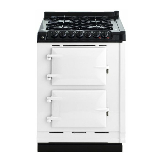
Page 14: Product View
RAPID BURNER GAS HOTPLATE SEMI RAPID BURNER SEMI RAPID BURNER WOK BURNER CONTROL PANEL REMOVABLE LINER GRILL PAN WITH GRID GRILL SHELF GRILL & CONVENTIONAL OVEN GRID SHELF FANNED OVEN ROASTING TIN (BAKING TRAY NOT SHOWN) FOR USE IN BOTH OVENS Fig. -
Page 15: Control Panel
CONTROL PANEL GAS HOB BURNERS REAR FRONT REAR FRONT LOWER GRILL LEFT LEFT RIGHT RIGHT OVEN OVEN LOWER OVEN OVEN NEON NEON Fig. 5 DESN 515698 A The GAS HOTPLATE CONTROL KNOBS can only be rotated anti-clockwise from the OFF position. -
Page 16: Gas Hotplate
GAS HOTPLATE The hotplate has four gas burners: rear left - rapid burner - rated at 3.0 kW front left and rear right - semi rapid burners - each rated at 1.75 kW front right - ultra rapid (wok) burner - rated at 3.5 kW The semi-rapid burners are especially suited for use with small pans and for gentle simmering or poaching. -
Page 17: The Grill And The Ovens
The large grill pan and grid are not designed to fit in the lower oven. If you also have an AGA DO NOT use the small roasting tin provided with the AGA in the Companion. Please use utensils provided and place on the grid shelves. -
Page 18: Oven Cooking Guide
OVEN COOKING GUIDE Cooking Hints Both ovens must be pre-heated until the neon light extinguishes. The guidelines are for cooking after the oven(s) have reached the desired temperature. Larger items may benefit from being turned. Shelf positions are counted from the top. Put dishes in the centre of the shelf. - Page 19 Top Oven (Conventional) Top Oven (Conventional) • Top Oven (Conventional) • Top Oven (Conventional) The cooking charts are a general guide but times and temperatures may vary according to individual recipes. The meat sections should be used as a guide but may vary according to the size, shape of joint on or off the bone. Thaw frozen joints thoroughly before cooking them.
- Page 20 Top Oven (Conventional) • Top Oven (Conventional) • Top Oven (Conventional) • Top Oven (Conventional) • Top Oven (Conventional) SHELF FOOD SETTING °C APPROXIMATE COOKING TIME POSITION Cakes and Biscuits Cakes and Biscuits Shortbread 45 mins - 1hr 3 - 4 hrs Very Rich Fruit Cake 130 - 140 Fruit Cake...
- Page 21 Lower Oven (Fanned) L o w e r O v e n ( F a n n e d ) • L o w e r O v e n ( F a n n e d ) • L o w e r O v e n ( F a n n e d ) The lower oven is a fan oven which means the air is circulated to create an even temperature throughout the oven.
- Page 22 Lower Oven (Fanned) • Lower Oven (Fanned) • Lower Oven (Fanned) • Lower Oven (Fanned) • Lower Oven (Fanned) SHELF APPROXIMATE COOKING TIME FOOD SETTING °C POSITION Cakes and Biscuits Shortbread 2 or 3 45 - 50 mins Very Rich Fruit Cake 120 - 130 3 - 4 hrs Fruit Cake...
-
Page 23: Cleaning And Caring For Your Cooker
Surfaces that require cleaning are: Enamelled Top and Front Plate The easiest way to clean the AGA top plate and front plate is to mop up spills as they happen. Baked on food is more difficult to clean but can usually be removed with proprietary vitreous enamel cleaners or mild cream cleaners using a cloth, or if necessary, a nylon scouring pad. - Page 24 Avoid the use of excessive water. DO NOT use oven cleaners, scouring pads and abrasive powder for cleaning plastic knobs. A wipe with a damp cloth should be sufficient. IMPORTANT: AGA recommend Vitreous Enamel Association approved cleaners for cleaning vitreous enamel surfaces of this product.
- Page 25 BURNER CAP RETAINING LUGS Fig. 6A DESN 511617 Fig. 6B DESN 513513 Fig. 6C DESN 513898...
-
Page 26: Servicing
SERVICING In the event of your appliance requiring maintenance, please call AGA Service or contact your authorised distributor/stockist. Your cooker must only be serviced by a Qualified Engineer from an authorised distributor/stockist. Do not alter or modify the cooker. Only the spares specified by the manufacturer, are to be fitted. -
Page 27: Wiring Diagram
AGA COMPANION/MODULE (WITH GAS HOB UNIT) UK & EUROPE COLOUR KEY BLUE WH - WHITE BK - BLACK YELLOW PK - PINK BR - BROWN PURPLE GR - GREY NOTE: IGNITION SWITCHES AND THERMOSTATS ARE SHOWN IN THE OFF POSITION WITH THE APPLIANCE COLD AND FAN OVEN DOOR CLOSED. - Page 28 For further advice or information contact your local AGA Specialist With AGA Rangemaster's policy of continuous product improvement, the Company reserves the right to change specifications and make modifications to the appliances described and illustrated at any time. Manufactured By...
Need help?
Do you have a question about the COMPANION and is the answer not in the manual?
Questions and answers