Table of Contents
Advertisement
Quick Links
INSTRUCTION MANUAL
MULTI POWER MONITORING UNIT
(clamp-on current sensor CLSE, Modbus)
BEFORE USE ....
Thank you for choosing M-System. Before use, please check
contents of the package you received as outlined below.
If you have any problems or questions with the product,
please contact M-System's Sales Office or representatives.
■ PACKAGE INCLUDES:
Multi power monitoring unit ..............................................(1)
Upper mounting adaptor ....................................................(2)
■ MODEL NO.
Confirm Model No. marking on the product to be exactly
what you ordered.
■ INSTRUCTION MANUAL
This manual describes necessary points of caution when
you use this product, including installation, connection and
basic maintenance procedures.
This unit is programmable by using the PC Configurator
Software. For detailed information on the PC configuration,
refer to the PMCFG users manual. The PMCFG PC Con-
figurator Software is downloadable at M-System's web site:
http://www.m-system.co.jp
POINTS OF CAUTION
■ CONFORMITY WITH EU DIRECTIVES
• This equipment is suitable for Pollution Degree 2, Meas-
urement Category II (input, transient voltage 4000V) and
Installation Category II (transient voltage 2500V). Prior
to installation, check that the insulation class of this unit
satisfies the system requirements. Insulation class of this
unit is as follows.
Input to Modbus
Input or Modbus to auxiliary
power
• Altitude up to 2000 meters.
• The equipment must be mounted inside a panel.
• The equipment must be installed such that appropriate
clearance and creepage distances are maintained to con-
form to CE requirements. Failure to observe these re-
quirements may invalidate the CE conformance.
• The actual installation environments such as panel con-
figurations, connected devices, connected wires, may af-
fect the protection level of this unit when it is integrated
in a panel system. The user may have to review the CE
requirements in regard to the whole system and employ
additional protective measures to ensure the CE conform-
ity.
• Install lightning surge protectors for those wires connect-
ed to remote locations.
■ AUXILIARY POWER INPUT RATING & OPERATIONAL RANGE
• Locate the auxiliary power input rating marked on the
product and confirm its operational range as indicated
below:
100 – 240V AC rating: 85 – 264V, 50/60 Hz, < 7VA
110 – 240V DC rating: 99 – 264V, < 1.2W
Reinforced insulation (400V)
Reinforced insulation (300V)
5-2-55, Minamitsumori, Nishinari-ku, Osaka 557-0063 JAPAN
Phone: +81(6)6659-8201 Fax: +81(6)6659-8510 E-mail: info@m-system.co.jp
MODEL
■ GENERAL PRECAUTIONS
• Before you remove or mount the unit, turn off the power
supply and input signal for safety.
• DO NOT set the switches on the module while the power
is supplied. The switches are used only for maintenance
without the power.
■ ENVIRONMENT
• Indoor use.
• Do not install the unit where it is directly exposed to rain,
water droplets or sunlight.
• When heavy dust or metal particles are present in the
air, install the unit inside proper housing with sufficient
ventilation.
• Do not install the unit where it is subjected to continuous
vibration. Do not subject the unit to physical impact.
• Environmental temperature must be within -10 to +55°C
(14 to 131°F) with relative humidity within 30 to 90% RH
in order to ensure adequate life span and operation.
■ WIRING
• Wiring to the unit must be conducted by qualified service
personnel.
• Do not install cables close to noise sources (relay drive
cable, high frequency line, etc.).
• Do not bind these cables together with those in which
noises are present. Do not install them in the same duct.
■ AND ....
• The unit is designed to function as soon as power is sup-
plied, however, a warm up for 10 minutes is required for
satisfying complete performance described in the data
sheet.
R9MWTU
EM-6221 Rev.9 P. 1 / 20
Advertisement
Table of Contents

Related Manuals for M-system R9MWTU


Summary of Contents for M-system R9MWTU
- Page 1 • Before you remove or mount the unit, turn off the power supply and input signal for safety. Thank you for choosing M-System. Before use, please check • DO NOT set the switches on the module while the power contents of the package you received as outlined below.
-
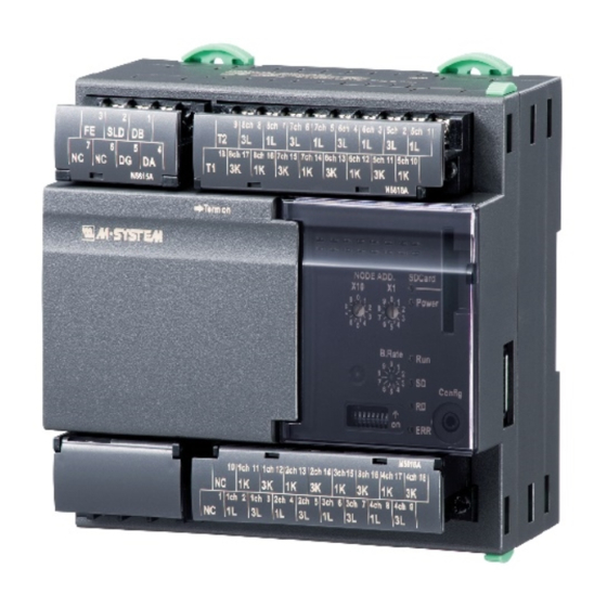
Page 2: Component Identification
Baud Rate Setting Factory setting : 00 Node Address Setting (x1) Node Address Setting (x10) EM-6221 Rev.9 P. 2 / 20 5-2-55, Minamitsumori, Nishinari-ku, Osaka 557-0063 JAPAN Phone: +81(6)6659-8201 Fax: +81(6)6659-8510 E-mail: info@m-system.co.jp... - Page 3 4ch 1L Ch.4, Current input 1L 4ch 1K Ch.4, Current input 1K 4ch 3L Ch.4, Current input 3L 4ch 3K Ch.4, Current input 3K EM-6221 Rev.9 P. 3 / 20 5-2-55, Minamitsumori, Nishinari-ku, Osaka 557-0063 JAPAN Phone: +81(6)6659-8201 Fax: +81(6)6659-8510 E-mail: info@m-system.co.jp...
-
Page 4: Installation
4 − 4.5 (.18) dia. MTG HOLE DIN RAIL 35 mm wide 75 (2.95) 6.5 (.25) 125 (4.92) 80 (3.15) [4 (.16)] 7−M3.5 SCREW TERMINALS 7.3 (.29) EM-6221 Rev.9 P. 4 / 20 5-2-55, Minamitsumori, Nishinari-ku, Osaka 557-0063 JAPAN Phone: +81(6)6659-8201 Fax: +81(6)6659-8510 E-mail: info@m-system.co.jp... - Page 5 CURRENT Ch. 2 CURRENT INPUT 1 CURRENT INPUT 2 CURRENT Ch. 7 CURRENT Ch. 3 CURRENT Ch. 8 CURRENT Ch. 4 CURRENT EM-6221 Rev.9 P. 5 / 20 5-2-55, Minamitsumori, Nishinari-ku, Osaka 557-0063 JAPAN Phone: +81(6)6659-8201 Fax: +81(6)6659-8510 E-mail: info@m-system.co.jp...
-
Page 6: Mounting Requirements
SINGLE MOUNTING 75 (2.95) – Pitch 130 (5.12) min. BASIC + EXTENSION UNIT 75 (2.95) 70.5 (2.78) – Pitch 223 (8.78) min. EM-6221 Rev.9 P. 6 / 20 5-2-55, Minamitsumori, Nishinari-ku, Osaka 557-0063 JAPAN Phone: +81(6)6659-8201 Fax: +81(6)6659-8510 E-mail: info@m-system.co.jp... -
Page 7: Wiring Instructions
When this unit is located at an end, turn the terminating resistor SW ON. The Host PC can be located at not only both ends but also any node of the of communication line. EM-6221 Rev.9 P. 7 / 20 5-2-55, Minamitsumori, Nishinari-ku, Osaka 557-0063 JAPAN Phone: +81(6)6659-8201 Fax: +81(6)6659-8510 E-mail: info@m-system.co.jp... -
Page 8: Modbus - Basics
Be sure to write the correct passcode in the register address 8977 before changing the register setting from ‘0’ (Write disable) to ‘1’ (Write enable). (*) Factory setting EM-6221 Rev.9 P. 8 / 20 5-2-55, Minamitsumori, Nishinari-ku, Osaka 557-0063 JAPAN Phone: +81(6)6659-8201 Fax: +81(6)6659-8510 E-mail: info@m-system.co.jp... - Page 9 Ch. 10 Reset count (DI 2 Reset count) 9006 Ch. 11 Reset count (DI 3 Reset count) 9011 Ch. 16 Reset count (DI 8 Reset count) EM-6221 Rev.9 P. 9 / 20 5-2-55, Minamitsumori, Nishinari-ku, Osaka 557-0063 JAPAN Phone: +81(6)6659-8201 Fax: +81(6)6659-8510 E-mail: info@m-system.co.jp...
-
Page 10: Modbus - Setting
S = S1 + S2 + S3 Note: ‘1,’ ‘2,’ ‘3’ in expressions like Q1, Q2, Q3 indicate ‘R,’ ‘S,’ ‘T phases’ respectively. EM-6221 Rev.9 P. 10 / 20 5-2-55, Minamitsumori, Nishinari-ku, Osaka 557-0063 JAPAN Phone: +81(6)6659-8201 Fax: +81(6)6659-8510 E-mail: info@m-system.co.jp... - Page 11 Ch. 16 setting Same as with the address 9393 through 9396 9456 Ch. 9 through 16 are valid only when the R9WTU-EP8 is used. EM-6221 Rev.9 P. 11 / 20 5-2-55, Minamitsumori, Nishinari-ku, Osaka 557-0063 JAPAN Phone: +81(6)6659-8201 Fax: +81(6)6659-8510 E-mail: info@m-system.co.jp...
- Page 12 Ch. 16 Input overload Same as with the address 9545 Ch. 9 through 16 are valid only when the R9WTU-EP8 is used. EM-6221 Rev.9 P. 12 / 20 5-2-55, Minamitsumori, Nishinari-ku, Osaka 557-0063 JAPAN Phone: +81(6)6659-8201 Fax: +81(6)6659-8510 E-mail: info@m-system.co.jp...
- Page 13 8 : 8 circuits 16 : 16 circuits (with the R9WTU-EP8) 9628 Number of counters 0 : None 8 : 8 points (with the R9WTU-ED16) EM-6221 Rev.9 P. 13 / 20 5-2-55, Minamitsumori, Nishinari-ku, Osaka 557-0063 JAPAN Phone: +81(6)6659-8201 Fax: +81(6)6659-8510 E-mail: info@m-system.co.jp...
-
Page 14: Modbus - Mapping
*3. Total current Single-phase/2-wire: Line 1 current Single-phase/3-wire: (Line 1 + 3) / 2 Three-phase/3-wire: (Line 1 + 2 + 3) / 3 EM-6221 Rev.9 P. 14 / 20 5-2-55, Minamitsumori, Nishinari-ku, Osaka 557-0063 JAPAN Phone: +81(6)6659-8201 Fax: +81(6)6659-8510 E-mail: info@m-system.co.jp... - Page 15 Apparent power, Phase 3 Apparent power AVG +118 +120 Apparent power Power factor, Phase 1 Power factor, Phase 2 Power factor, Phase 3 Power factor EM-6221 Rev.9 P. 15 / 20 5-2-55, Minamitsumori, Nishinari-ku, Osaka 557-0063 JAPAN Phone: +81(6)6659-8201 Fax: +81(6)6659-8510 E-mail: info@m-system.co.jp...
- Page 16 Max. energy Max. pulse count Max. pulse count date/time Max. energy data/time *. The value can be preset by writing. (Ver.1.30 or later) EM-6221 Rev.9 P. 16 / 20 5-2-55, Minamitsumori, Nishinari-ku, Osaka 557-0063 JAPAN Phone: +81(6)6659-8201 Fax: +81(6)6659-8510 E-mail: info@m-system.co.jp...
- Page 17 1 : ON 7751 DI 7 Status 0 : OFF 1 : ON 7752 DI 8 status 0 : OFF 1 : ON EM-6221 Rev.9 P. 17 / 20 5-2-55, Minamitsumori, Nishinari-ku, Osaka 557-0063 JAPAN Phone: +81(6)6659-8201 Fax: +81(6)6659-8510 E-mail: info@m-system.co.jp...
- Page 18 DO 8 Output contact at the Extension Unit is turned on/off by writing in the address. 0 : OFF / 1 : ON EM-6221 Rev.9 P. 18 / 20 5-2-55, Minamitsumori, Nishinari-ku, Osaka 557-0063 JAPAN Phone: +81(6)6659-8201 Fax: +81(6)6659-8510 E-mail: info@m-system.co.jp...
- Page 19 DATA LOGGING IN SD CARD ■ GENERAL DESCRIPTION ■ DIRECTORY The R9MWTU is equipped with a SD card slot. The unit transfers to the card at 0 minute every hour its in- Device ternal memory data: energy per hour; and voltage, current, XXXXXXXX power and energy per minute.
-
Page 20: Lightning Surge Protection
Current 3 Neutral current Current 3 LIGHTNING SURGE PROTECTION M-System offers a series of lightning surge protector for protection against induced lightning surges. Please contact M-System to choose appropriate models. EM-6221 Rev.9 P. 20 / 20 5-2-55, Minamitsumori, Nishinari-ku, Osaka 557-0063 JAPAN...
Need help?
Do you have a question about the R9MWTU and is the answer not in the manual?
Questions and answers