Table of Contents
Advertisement
Quick Links
Advertisement
Table of Contents

Related Manuals for Lumel N32H


Summary of Contents for Lumel N32H
- Page 1 N32H--09 User's manual DIGITAL PANEL METER N32H SERVICE MANUAL...
-
Page 2: Table Of Contents
N32H--09 User's manual Contents 1 Application............................3 2 Meter set............................5 3 Basic requirements, operational safety.....................5 4 Installation............................6 4.1 Installation method........................6 4.2 External connection diagram....................7 5 Service............................10 5.1 Description of the frontal plate....................10 5.2 Buttons' functions........................12 5.3 Programming meter parameters....................13 5.3.1 How to change quantity of a selected parameter............15 5.3.2 Programmable meter parameters, default parameters.............15... -
Page 3: Application
User's manual 1 Application The N32H meter is a digital panel meter adapted to be fixed to the panel. The N32H meters are designed to measure voltages, currents, power, energy and capacity in DC circuits. Current measurement is carried out using an external current shunt, which enables easy adjustment of the current measuring range to the requirements of the application. - Page 4 N32H--09 User's manual Possibility to simultaneously display two selected measured quantities or for • example, a measured quantity and a unit or time. Programmable display precision with the function of automatic setting of the • decimal point and the multiplier (kilo, mega) displayed with the unit.
-
Page 5: Meter Set
Seal – 1 pc • 3 Basic requirements, operational safety In terms of a user safety, the N32H meter meets the requirements of the EN61010-1 standard for the devices intended for use in facilities compliant with the third category of installations. -
Page 6: Installation
Removal of the meter electronics during the warranty period voids the warranty. • 4 Installation 4.1 Installation method The N32H meters are designed to be mounted in a panel. Prior to installation a 92 +0.6 +0.6 mm slot must be made in the panel. The maximum thickness of the panel material cannot exceed 6 mm. -
Page 7: External Connection Diagram
Fig. 3: Meter overall dimensions. 4.2 External connection diagram The N32H meter has two detachable terminal strips to connect the wires of a cross-section up to 2.5 mm . The view of the meter from the connectors' side is shown in Fig. 5. The upper terminal strip is optional and depends on the accessories of the meter. - Page 8 N32H--09 User's manual Note: Unused terminals of the terminal strips (NC) must not be connected to any signals. Fig. 5: Signals on the terminal strips. Detailed description of the signals is shown in the table below, and the connection of the measuring signals is shown in Fig.
- Page 9 8, 14, 29 Unused terminals. Should be left unconnected. The connection of the basic measured signals is shown below. The N32H meter can also be used to measure only voltage or only current. Fig. 6: Connection of the N32H meter,...
-
Page 10: Service
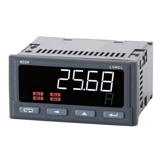
N32H--09 User's manual Symbols shown in the diagram: N32H meter: ● U - voltage measurement terminal. The voltage is measured between the U-C terminals. ● I - voltage measurement input from the shunt - indirect current measurement method. ● C - common terminal, a ground of the measuring system. - Page 11 N32H--09 User's manual Fig. 7: Front panel of the meter. Designation Description The upper (main) line of the display has 6 characters used to display a measuring value or a parameter value during the meter configuration. The lower (auxiliary) line of the display has 5 characters used to display a measuring value, not converted by the individual characteristic or, according to configuration, a unit or current time.
-
Page 12: Buttons' Functions
N32H--09 User's manual 5.2 Buttons' functions Cancel button: Exiting the menu and exit to the main screen. • Exiting a lower level of the menu and return to a higher level. • Canceling changing the set value (when editing the parameter value) •... -
Page 13: Programming Meter Parameters
N32H--09 User's manual Deleting alarm memory - hold down the buttons for 3 seconds. ClrAL message will be displayed after deleting alarm memory. All the events of deleting of saved minimum, maximum values and alarm activation memory are indicated by the meter by displaying an appropriate message. - Page 14 N32H--09 User's manual The buttons allow to navigate the menu of the meter. After selecting the group of the parameters which configuration is to be changed, press the confirm button to move to the parameters of the group. The parameter which value is to be modified is selected the same way as the selection of the group.
-
Page 15: How To Change Quantity Of A Selected Parameter
5.3.2 Programmable meter parameters, default parameters The N32H meters have a number of programmable parameters, which enable the meter to be adapted to the requirements of application. The parameters grouped according to the menu are shown in the tables below. - Page 16 N32H--09 User's manual Table 1 Parameter Description Range of changes symbol Default: 50V 50V – rated measurement range 50 V Voltage measurement range in voltage 100V – rated measurement range 100 V measurement loop 150V – rated measurement range 150 V 300V –...
- Page 17 N32H--09 User's manual reset/setting the counter. -99999M...999999M Pulse weight in kWh, portion of an energy Default: 1 corresponding to one pulse on the binary output. 0.001...999999 [kWh] The EP W value determines at what change of the energy counter one pulse will be assigned to the binary output.
- Page 18 N32H--09 User's manual E – energy counter value. CAP – accumulated current counter value (capacity). AVG U – voltage mean value in a given averaging period. AVG I – current mean value in a given averaging period. AVG P – power mean value in a given averaging period.
- Page 19 N32H--09 User's manual Table 4 Parameter Description Range of changes symbol Default: 1 MODBUS network meter address 1…247 The transmission frame type of RS-485 Default: F8N1 interface. Setting the parity bits and the number of stop bits. F8N1 F8N2 F8O1 F8E1 Default: 9.6k...
-
Page 20: Meter Functions
5.4.1 Measurement The N32H meters continuously measure a voltage (rated) and a current (rated) and based on these measurements calculate the power value (TRUE RMS value), energy (calculated based on instantaneous values of power) and the value of accumulated current (capacity), which quantifies the amount of charge transferred in Ah. -
Page 21: Averaging The Measuring Quantities
N32H--09 User's manual The measuring values are continuously analyzed during averaging, and additionally, the minimum and maximum measuring values are determined during the averaging period, as well as the total minimum and maximum measuring values, which are saved in the non- volatile memory of the meter. -
Page 22: Minimum And Maximum Measuring Values
N32H--09 User's manual The buffers for average value calculation have a length of 1800 single measurements, and each of the averaged values has a separate data buffer, therefore the average value calculated by the moving window method can be updated less frequently than it would result from the time of a single measurement. -
Page 23: Voltage Measurement Compensation
5.4.2 Analog output The N32H meters can have one analog output (depends on the ordering code) connected to the meter terminals as a voltage output (0...10 V output) and as a current output (0...20 mA or 4...20 mA). -
Page 24: Alarm Outputs
5.4.3 Alarm outputs The N32H meters are equipped with one alarm output as standard. They can have 4 alarm outputs as an option, including three outputs with a switching contact. The alarm output element are electro-magnetic relays. If the meter is physically equipped with one alarm, 4 alarms are still available in the meter menu. -
Page 25: Binary Output
The alarm event could be registered if the alarm memory is enabled. 5.4.4 Binary output The N32H meters can have a galvanically separated optional binary output, which is designed to generate pulses corresponding to the counting of a given portion of energy by the energy counter. -
Page 26: Rs-485 Interface
The terminals A, B and GNDI terminals which location is shown on Fig. 5 allow to connect the RS-485 interface to the N32H meter. It is required to connect the lines A and B in parallel with their equivalents in other devices to obtain the correct transmission. -
Page 27: Description Of The Modbus Protocol Implementation
B lines should be one pair and are connected with their equivalents of other devices in the network. The cable shield should be connected to the protective terminal in close proximity to the N32H meter. The cable shield of the interface cable should be connected to the protective terminal only in one point. -
Page 28: Implemented Functions Of Modbus Protocol
B1 B0 B3 B2. The table below shows the register map of the N32H meter. The addresses in the table are the physical addresses. The register number should be increased by 1 when using the programs where the addresses are provided in a logical format. - Page 29 N32H--09 User's manual Value Rated range (measuring range) 50 V (-75...75 V) 100 V (-160...160 V) 150 V (-300...300 V) 300 V (-600...600 V) 600 V (-1200...1200 V) 4001 1...60000 Rated current of the connected shunt in amperes. 4002 30…1500 Rated voltage of the connected shunt in mV.
- Page 30 N32H--09 User's manual 0000.00 000.000 00.0000 0.00000 Automatic - the position of the decimal point is set for maximum resolution. Contents of the bottom line of the display Value Description Unit of main displayed value. Voltage measuring value Current measuring value...
- Page 31 N32H--09 User's manual Power measuring value Voltage mean value Current mean value Power mean value Energy counter content Accumulated current counter content Current time RS-485 4015 1...247 RS–485 – MODBUS network meter address RS–485 – data transmission frame type (format)
- Page 32 N32H--09 User's manual event memory function. Alarm 2 4024 0..3 Value controlling the alarm, as for the alarm no. 1. 4025 0...6 Alarm type, as for the alarm no. 1. 4026 0...900 Alarm activation delay in seconds. 4027 0...900 Alarm deactivation delay in seconds.
-
Page 33: Registers 4200 - 4233
N32H--09 User's manual 4051 0, 1 Alarm 1 - delete alarm memory. Entering the value 1 deletes the alarm event memory. 4052 0, 1 Alarm 2 - delete alarm memory. Entering the value 1 deletes the alarm event memory. 4053 0, 1 Alarm 3 - delete alarm memory. - Page 34 N32H--09 User's manual 4213 Current time - minutes. 4214 Current time - seconds. State of the internal time clock Value Description No clock errors. 4215 Lost time settings. Clock initialization error - faulty clock. Clock setting error. Alarms - alarm event memory 4216 Alarm 1: Value 1 - active mode to register the alarm event.
-
Page 35: Registers 7500 - 7515 And 7000 - 7031
N32H--09 User's manual 5.5.4.3 Registers 7500 – 7515 and 7000 – 7031 The 32-bit and the corresponding 16-bit registers with measuring and calculated data. The address entered in the address field is for 32-bit float variables or in the second column for the values stored in two 16-bit registers, where the value stored in two registers is of float type. -
Page 36: Registers 7600 - 7677 And 7200 - 7355
N32H--09 User's manual 5.5.4.4 Registers 7600 – 7677 and 7200 – 7355 The 32-bit and the corresponding 16-bit registers with the configuration parameters. Address Address (32- (value in 2 16- Permissible values Description Default bit float registers) bit registers) Minimum and maximum displayed value Display narrowing lower threshold. -
Page 37: Error Codes
User's manual 6 Error codes The N32H meters have several diagnostic functions and settings built-in that allow to limit the displaying. So the display may show and the status registers may store information about the diagnosed error, event or fault. Possible messages and their potential causes are listed below. -
Page 38: Technical Data
N32H--09 User's manual 7 Technical data Measuring ranges Input type Indication range Class (rated range) (rated range) Voltage measuring loop Voltage 50 V -75...75 V (50 V) Voltage 100 V -160...160 V (100 V) Voltage 150 V -300...300 V (150 V) Voltage 300 V -600...600 V (300 V) - Page 39 N32H--09 User's manual 38400, 57600, 115200 Alarm outputs: NO relay: 5 A / 250 V AC; 5 A / 30 V DC (listed current values are the maximum • permissible values. Operation at maximum load significantly shortens lifespan of the relay).
- Page 40 N32H--09 User's manual Protection grade ensured From the front IP65 From the terminals side IP10 Weight and dimensions Meter weight < 0.2 kg Dimensions (see Fig. 3) 96 x 48 x 93 mm Electromagnetic compatibility Noise immunity: acc. to EN 61000-6-2 Noise emission: acc.
-
Page 41: Ordering Code
N32H--09 User's manual 8 Ordering code Panel meter N32H type: XXXXXXX Supply voltage 85..253 V AC, 90...300 V DC 20...40 V AC, 20...60 V DC Outputs / Interface 1 relay output, RS-485 4 relay outputs, RS-485 4 relay outputs, RS-485, 1 analog output... - Page 42 N32H--09 User's manual LUMEL S.A. ul. Słubicka 4, 65-127 Zielona Góra, POLAND tel. 68 45 75 100 www.lumel.com.pl Technical support: tel.: (+48 68) 45 75 143, 45 75 141, 45 75 144, 45 75 140 e-mail: export@lumel.com.pl Export department: tel.: (+48 68) 45 75 130, 45 75 131, 45 75 132 e-mail: export@lumel.com.pl...
Need help?
Do you have a question about the N32H and is the answer not in the manual?
Questions and answers