Table of Contents
Advertisement
Quick Links
Advertisement
Table of Contents

Related Manuals for Lumel N32P


Summary of Contents for Lumel N32P
- Page 1 N32P-09 User's manual DIGITAL PANEL METER N32P SERVICE MANUAL...
-
Page 2: Table Of Contents
N32P-09 User's manual Contents 1 Application............................3 2 Meter set............................5 3 Basic requirements, operational safety.....................5 4 Installation............................6 4.1 Installation method........................6 4.2 External connection diagram....................7 5 Service............................10 5.1 Description of the frontal plate....................10 5.2 Buttons' functions........................12 5.3 Programming meter parameters....................13 5.3.1 How to change quantity of a selected parameter............15 5.3.2 Programmable meter parameters, default parameters.............16... -
Page 3: Application
User's manual 1 Application The N32P meter is a digital panel meter adapted to be fixed to the panel. The N32P meters are designed to measure voltage, current, power and energy in AC circuits. Voltage and current measurement can be dome directly or using an external current and voltage transformers. - Page 4 N32P-09 User's manual Programmable display precision with the function of automatic setting of the • decimal point and the multiplier (kilo, mega) displayed with the unit. Possibility to program the measuring range (narrowing) for the selected displayed • value. Additional measurement of minimum and maximum values during the moving •...
-
Page 5: Meter Set
Seal – 1 pc • 3 Basic requirements, operational safety In terms of a user safety, the N32P meter meets the requirements of the EN61010-1 standard for the devices intended for use in facilities compliant with the third category of installations. -
Page 6: Installation
Removal of the meter electronics during the warranty period voids the warranty. • 4 Installation 4.1 Installation method The N32P meters are designed to be mounted in a panel. Prior to installation a 92 +0.6 +0.6 mm slot must be made in the panel. The maximum thickness of the panel material cannot exceed 6 mm. -
Page 7: External Connection Diagram
The external dimensions of the meter are shown in Fig. 3. 4.2 External connection diagram The N32P meter has three detachable terminal strips to connect the wires of a cross- section up to 2.5 mm . The view of the meter from the connectors' side is shown in Fig. 5. - Page 8 N32P-09 User's manual Fig. 5: Signals on the terminal strips. Detailed description of the signals is shown in the table below, and the connection of the measuring signals is shown in Fig. 6. Terminal Function Description 2, 4, 5, 6...
- Page 9 3, 7, 14, Unused terminals. Should be left unconnected. The connection of the basic measured signals is shown below. The N32P meter can also be used to measure only voltage or only current. Fig. 6: Connection of the N32P meter,...
-
Page 10: Service
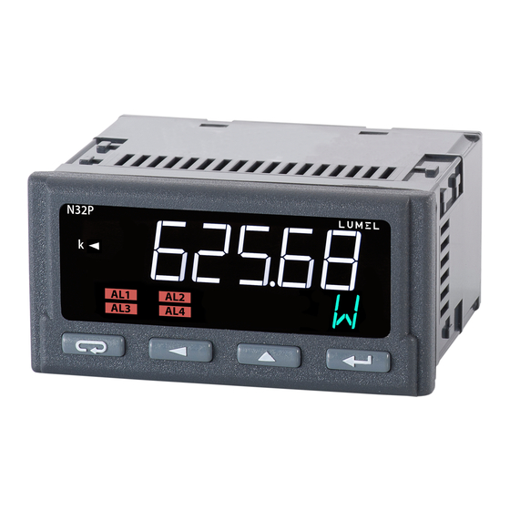
N32P-09 User's manual 5 Service The N32 meter user interface includes an LCD display and the buttons which enable to display the measuring value, a full configuration and setting of the meter or modification of the parameters. After turning the meter on the display shows the name of the meter and the software version. -
Page 11: Buttons' Functions
N32P-09 User's manual 3,500,000 W. Alarm status field. This field contains the indicator informing about the alarm status. Illuminated alarm indicator means that an alarm event is in progress and the relay corresponding to the alarm is activated. Flashing symbol means that the alarm state is saved (if the alarm memory is activated). -
Page 12: Programming Meter Parameters
N32P-09 User's manual Confirm button: Entering the programming mode (holding down the button for at least 3 • seconds). Navigating the menu - entering the parameter value editing mode or • entering the selected lower level of the menu. Accepting the changed parameter value. - Page 13 N32P-09 User's manual Fig. 8: View of meter menu. While navigating the meter main menu with the groups of the parameters, the upper line of the display shows the name of the group and the lower line continuously displays the word MENU.
-
Page 14: How To Change Quantity Of A Selected Parameter
N32P-09 User's manual Reset (enter initial value) energy counter. Function of a lower Minimum value on Maximum value on Resolution - position Selection of main line of the display - the display. For the display. For of the decimal point. -
Page 15: Programmable Meter Parameters, Default Parameters
N32P-09 User's manual display. Entering an incorrect value of a given parameter causes that the new value is not accepted and the parameter will automatically have the previous value. To change the parameters other than numerical select the appropriate setting from the parameter list using the buttons . - Page 16 N32P-09 User's manual Note: IPRIM and ISEC define the current ratio that directly affects the measuring values of the parameters measured by the meter. The parameters IPRIM and ISEC should be set to the same value, if the current transformer is not used in the system.
- Page 17 N32P-09 User's manual Table 2 Parameter Description Range of changes symbol Default : U U – currently measured voltage value. I – currently measured current value. P – currently measured active power value. Q – currently measured reactive power value.
- Page 18 N32P-09 User's manual 0.00000 AUTO – automatic position of the decimal point for maximum possible resolution. Default : UNIt UNIt – unit U – currently measured voltage value. I – currently measured current value. P – currently measured active power value.
- Page 19 N32P-09 User's manual Table 3 Parameter Description Range of changes symbol Default : U U – currently measured voltage value. I – currently measured current value. P – currently measured active power value. Q – currently measured reactive power value.
- Page 20 N32P-09 User's manual Table 4 Parameter Description Range of changes symbol Default : 1 MODBUS network meter address 1…247 Default : F8N1 The transmission frame type of RS-485 F8N1 interface. Setting the parity bits and the F8N2 number of stop bits.
-
Page 21: Meter Functions
5.4.1 Measurement The N32P meters continuously measure RMS voltage, current and power. They calculate energy, power factor and power tangent based on the measured values. Both, the power factor value and the power tangent are calculated based on the power triangle. -
Page 22: Averaging The Measuring Quantities
N32P-09 User's manual synchronization should only be selected if the meter is used only for current measurement. Sampling is 8,000 measurements per second. The measuring periods (input signal period) are synchronized with the signal from the internal zero crossing detector. A single measurement is made for the number of periods corresponding to a time of 100 ms. -
Page 23: Minimum And Maximum Measuring Values
N32P-09 User's manual the current measuring value after the first stage of averaging. Additionally, the average value is calculated for each of the measuring parameters, and the averaging period is defined by the user by defining AVGPE parameter in minutes. The average value can additionally be synchronized with the internal time clock. -
Page 24: Analog Output
, and then the button 5.4.2 Analog output The N32P meters can have one analog output (depends on the ordering code) connected to the meter terminals as a voltage output (0...10 V output) and as a current output (0...20 mA or 4...20 mA). The analog output is galvanically separated from the other meter circuits. -
Page 25: Alarm Outputs
5.4.3 Alarm outputs The N32P meters are equipped with one alarm output as standard. They can have 4 alarm outputs as an option, including three outputs with a switching contact. The alarm output element are electro-magnetic relays. If the meter is physically equipped with one alarm, 4 alarms are still available in the meter menu. -
Page 26: Binary Output
The alarm event could be registered if the alarm memory is enabled. 5.4.4 Binary output The N32P meters can have a galvanically separated optional binary output, which is designed to generate pulses corresponding to the counting of a given portion of energy by the energy counter. -
Page 27: Rs-485 Interface
Fig. 12: An example of connecting a binary output to a PLC controller. The figure above shows the examples of connecting the binary output of the N32P meter to a PLC controller. The diagram in Fig. a shows the controller input to work with PNP sensors, while Fig. -
Page 28: Description Of The Modbus Protocol Implementation
N32P-09 User's manual the RS-485 interface to the N32P meter. It is required to connect the lines A and B in parallel with their equivalents in other devices to obtain the correct transmission. The connection should be made using twisted pair screened cable in such a way that the A and B lines should be one pair and are connected with their equivalents of other devices in the network. -
Page 29: Implemented Functions Of Modbus Protocol
B1 B0 B3 B2. The table below shows the register map of the N32P meter. The addresses in the table are the physical addresses. The register number should be increased by 1 when using the programs where the addresses are provided in a logical format. -
Page 30: Registers 3000 - 3127
N32P-09 User's manual 5.5.4.1 Registers 3000 – 3127 Address Permissible values Unit Description Voltage harmonics Main voltage harmonic - value expressed as a percentage multiplied 3000 0...65535 % * 100 by 100. 3001 0...65535 % * 100 Second voltage harmonic 0...65535... - Page 31 N32P-09 User's manual Averaging period synchronization with the real time clock. The parameter is applicable only if 60 minutes is a multiple of the averaging time. 4006 0, 1 Value Format Synchronization disabled Synchronization enabled Selection of the counter controlling the binary output (pulse).
- Page 32 N32P-09 User's manual 0.00000 Automatic - the position of the decimal point is set for maximum resolution. Contents of the bottom line of the display Value Description Unit of main displayed value. Voltage measuring value. Current measuring value. Active power measuring value Reactive power measuring value.
- Page 33 N32P-09 User's manual Quantity controlling the analog output signal Value Description Voltage measuring value. Current measuring value. Active power measuring value Reactive power measuring value. Apparent power measuring value Power factor value (angle cosine of the power triangle). Power tangent value.
- Page 34 N32P-09 User's manual register 4013 (quantity controlling the analog output). 4019 0...6 Alarm type (see section 5.4.3) Value Description n-on n-off H-on – manually disabled H-off – manually enabled REG – state controlled by the RS-485 interface 4020 0...900 Alarm activation delay in seconds.
- Page 35 N32P-09 User's manual applying the changes. Alarms - Control Alarm 1 - alarm state control for the active alarm in REG mode. 4046 0, 1 Entering the value 1 activates the alarm. Entering the value 0 deactivates the alarm. 4047 0, 1 Alarm 2 - alarm state control for the active alarm in REG mode.
-
Page 36: Registers 4200 - 4261
N32P-09 User's manual Description Reset/set active import energy counter. Reset/set active export energy counter. Reset/set reactive import energy counter. Reset/set reactive export energy counter. Reset apparent energy counter. Restore default settings Entering 1 restores the default settings 4056 0, 1 (default configuration) and resets this register. - Page 37 N32P-09 User's manual 4223 Active export energy counter in Ws - 64-bit 4224 4225 The registers store 64-bit content of active export energy counter in Ws (Watt seconds), the register 4224 stores the highest 16-bit of the word and the register 4227 stores the lowest 16-bit of the word.
-
Page 38: Registers 7500 - 7559 And 7000 - 7119
N32P-09 User's manual 4260 Alarm 3 active. 4261 Alarm 4 active. 5.5.4.4 Registers 7500 – 7559 and 7000 – 7119 The 32-bit and the corresponding 16-bit registers with measuring and calculated data. The address entered in the address field is for 32-bit float variables or in the second column for the values stored in two 16-bit registers, where the value stored in two registers is of float type. -
Page 39: Registers 7600 - 7677 And 7200 - 7355
N32P-09 User's manual 7531 7062 Registered power factor minimum value (cos) 7532 7064 Registered power factor maximum value (cos) 7533 7066 Registered power tangent minimum value (tan) 7534 7068 Registered power tangent maximum value (tan) 7535 7070 Registered signal frequency minimum measuring value [Hz]... -
Page 40: Error Codes
Alarm 4 – alarm state change upper threshold. 6 Error codes The N32P meters have several diagnostic functions and settings built-in that allow to limit the displaying. So the display may show and the status registers may store information about the diagnosed error, event or fault. Possible messages and their potential causes are listed below. -
Page 41: Technical Data
N32P-09 User's manual Lost real time clock settings. The message is displayed only when turning the meter on. Time and date must be set. If the message still appears when turning the meter on after setting the time and date, please contact the Service Department because a backup battery may require to be replaced. - Page 42 N32P-09 User's manual Active energy 0...9 999 999.9 kWh Reactive energy 0...9 999 999.9 kvarh Currents and voltages THD 0...100% Current and voltage 0...100% harmonics Frequency 35...65...100 Current time 00.00...23.59 ±20 ppm – voltage ratio; K – current ratio * - parameters calculated based on the power triangle. Meter accuracy class depends on the accuracy of the active and apparent power measurement.
- Page 43 N32P-09 User's manual relay). Three relays with a switching contact (option): 6 A / 250 V AC; 6 A / 30 V DC; • 0.15 A / 250 V DC. Maximum switching current 10 A / 20 ms. Analog output...
-
Page 44: Ordering Code
50 V for the circuits: auxiliary supply, RS-485 interface, analog output Altitude a.s.l. < 2000 m 8 Ordering code Panel meter N32P type- XXXXXXX Supply voltage 85..253 V AC, 90...300 V DC 20...40 V AC, 20...60 V DC Outputs / Interface... - Page 45 N32P-09 User's manual LUMEL S.A. ul. Słubicka 4, 65-127 Zielona Góra, POLAND tel. 68 45 75 100 www.lumel.com.pl Technical support: tel.: (+48 68) 45 75 143, 45 75 141, 45 75 144, 45 75 140 e-mail: export@lumel.com.pl Export department: tel.: (+48 68) 45 75 130, 45 75 131, 45 75 132 e-mail: export@lumel.com.pl...
Need help?
Do you have a question about the N32P and is the answer not in the manual?
Questions and answers