Table of Contents
Advertisement
Available languages
Available languages
Quick Links
Advertisement
Table of Contents

Related Manuals for Lumel N30O


Summary of Contents for Lumel N30O
- Page 1 CYFROWY MIERNIK TABLICOWY DIGITAL PANEL METER N30O INSTRUKCJA OBSŁUGI SZYBKI START USER’S MANUAL QUICK START Zeskanuj mnie Zeskanuj kod Scan the code Pełna wersja instrukcji dostępna na Full version of user’s manual available at www.lumel.com.pl...
- Page 2 1. WYMAGANIA PODSTAWOWE, BEZPIECZEÑSTWO U¯YTKOWANIA W zakresie bezpieczeństwa użytkowania miernik odpowiada wymaganiom normy PN-EN 61010-1. - szczególnie ważne, należy zapoznać się przed podłą- czeniem miernika. Nieprzestrzeganie uwag oznaczonych tym symbolem może spowodować uszkodzenie miernika. - należy zwrócić uwagę, gdy miernik pracuje niezgodnie z oczekiwaniami.
- Page 3 Rys. 1. Mocowanie miernika Rys. 2. Wymiary gabarytowe 2.1. Wyprowadzenia sygnałów Patrz str.26 2.2. Schematy podłączeñ zewnêtrznych Patrz str. 26.
-
Page 4: Opis Wyświetlacza
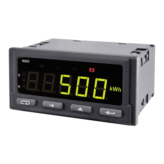
3. OBS£UGA 3.1. Opis wyświetlacza Rys. 5. Opis płyty czołowej miernika 3.2. Komunikaty po włączeniu zasilania Po włączeniu zasilania miernik wyświetla nazwę miernika N30-o, a na- stępnie wersję programu w postaci x.xx – gdzie x.xx jest numerem aktu- alnej wersji programu lub numerem wykonania specjalnego. Następnie miernik dokonuje pomiarów i wyświetla wartość... - Page 5 - przycisk zwiększania wartości: Þ wyświetlanie wartości maksymalnej. Naciśnięcie przycisku powo- duje wyświetlanie wartości maksymalnej przez około 3 sekundy, Þ wejście do poziomu grupy parametrów, Þ poruszanie się po wybranym poziomie, Þ zmiana wartości wybranego parametru - zwiększanie wartości, - przycisk zmiany cyfry: Þ...
- Page 6 Wciśnięcie i przytrzymanie kombinacji przycisków przez ponad 3 sekundy powoduje start zliczania (dla trybu licznika impulsów i licznika czasu pracy), jeżeli funkcja klawiszy jest włączona. Wciśnięcie i przytrzymanie przez około 3 sekundy przycisku powoduje wejście do matrycy programowania. Matryca programowa- nia może zostać...
- Page 10 3.4.1 Sposób zmiany wartości wybranego parametru. W celu zwiększenia wartości wybranego parametru należy wcisnąć przycisk . Jednokrotne wciśnięcie przycisku powoduje zwięk- szenie wartości o 1. Zwiększenie wartości przy wyświetlanej cyfrze 9 powoduje ustawienie 0 na tej cyfrze (lub znaku minus w przypadku najstarszej cyfry wyświetlacza).
-
Page 11: Dane Techniczne
4. DANE TECHNICZNE Zakresy pomiarowe. Tablica 1 Rodzaj wejścia Zakres wskazań Klasa Liczba impulsów Cntr1, -19999..99999 ±1 impuls Cntr2 Częstotliwość <10kHz 0,05...99999 Hz 0,01 1...99999 kHz Częstotliwość >10kHz 0,01 (zakres pomiaru do 1MHz) Prędkość obrotowa 0,05...99999 [Obr/min] 0,01 Okres t<10s 0,0001...11 [s] 0,01 Okres t>10s... - Page 12 Protokó³ transmisji: MODBUS RTU B³ąd wyjścia analogowego: 0,2% zakresu ustawionego. Stopień ochrony zapewniany przez obudowę: - od strony czołowej IP65 - od strony zacisków IP10 Masa: < 0,2 kg Wymiary: 96 ´ 48 ´ 93 mm Warunki odniesienia i znamionowe warunki użytkowania: - napięcie zasilania: 85...253 V d.c./a.c.
- Page 13 5. KOD WYKONAÑ Tablica 2 N30O X X XX XX X Napięcie zasilania: 85...253 V a.c. (40...400 Hz) lub d.c. 20...40 V a.c. (40...400 Hz) lub d.c. Dodatkowe wyjścia: brak wyjście OC, RS485, wyjścia analogowe wyjście OC, RS485, wyjścia analogowe, wyjścia przekaźnikowe przełączne...
-
Page 14: Basic Requirements, Operational Safety
1. BASIC REQUIREMENTS, OPERATIONAL SAFETY In the safety service scope, the N30O meter meets the requirements of the EN 61010-1 standard. Mentioned below applied symbols mean: - especially important, one must acquaint with this information before connecting the meter. The non-observance of notices marked by this symbol can occasion injures of the personnel and a damage of the instrument. -
Page 15: Installation
2. INSTALLATION The meter has separable strips with screw terminals, what enables the connection of external wires of 1.5 mm cross-section for input signals and 2.5 mm for other signals. ´ 45 One must prepare a hole of 92 +0.6 +0.6 mm in the panel, which the thickness should not exceed 6 mm. -
Page 16: Display Description
Fig. 5. Description of the Meter Frontal Plate 3.2. Messages after Switching the Supply on After switching the supply on, the meter displays the meter name N30O and next, the program version in the shape „ x.xx” – where x.xx is the number of the current program version or the number of a custom-ma- de option. - Page 17 - button increasing the value: Þ display of maximal value, The pressure of the button causes the display of the maximal value during ca 3 seconds, Þ entry in the level of the parameter group, Þ moving through the selected level, Þ...
- Page 18 The pressure and holding down the button during 3 seconds causes the entry to the programming matrix. The programming matrix can be proteced wit security code. The pressure and holding down the button during 3 seconds causes the entry to the menu monitoring meter parameters . One must move through the monitoring menu by means of buttons.
- Page 22 3.4.1. Value Change Way of the Chosen Parameter In order to increase the value of the selected parameter, one must press the button. A single pressure of the button, causes the increase of the value of 1. The increase of value when displaying the di- git 9 causes the setting of 0 on this digit.
-
Page 23: Technical Data
4. TECHNICAL DATA Measuring Ranges. Table 1 Kind of inputs Indication range Class Number of pulses -19 999..99 999 ±1 pulse Cntr1, Cntr2 Frequency <10 kHz 0.05...99 999 Hz 0.01 Frequency >10 kHz 1...99 999 kHz 0.01 Rotational speed 0.05...99 999 [Rev/min] 0.01 Period t <... - Page 24 Transmission protocol: MODBUS RTU Error of analog output: 0.2% of the set range Protection level ensured by the casing: - frontal side: IP65 - terminal side: IP10 Weight < 0.2 kg Overall dimensions: 96 ´ 48 ´ 93 mm (with terminals) Reference Conditions and Rated Operating Conditions: - supply voltage: 85...253 V d.c./a.c.
-
Page 25: Order Codes
5. ORDER CODES Table 2 N30O X X XX XX X Supply: 85...253 V a.c.(40...400 Hz) or d.c. 20...40 V a.c. (40...400 Hz) or d.c.d.c. Additional outputs: lack OC output, RS-485, analog outputs OC output, RS-485, analog outputs switched-over relay outputs Unit: unit code acc. - Page 26 schematy podłączeń electrical connections 4.1. Wyprowadzenia sygnałów Na rys. 3. przedstawiono sygnały wyprowadzone na złącza miernika. Wszystkie sygnały wejściowe są separowane między sobą oraz odse- parowane od pozostałych obwodów. Obwody kolejnych grup sygna- łów są separowane między sobą. 4.1. Lead-out of Signals Signals led out on the meter connectors are presented on the fig.
- Page 27 Zaciski Opis Zaciski Opis W3- wejście główne. Zliczanie 13-14 wyjście alarmowe 2 przekaźnikowe impulsów w dół. 15-16 wyjście 24V do zasilania W2 - wejście dodatkowe. Licznik zewnętrznych przetworników pomocniczy. 17-18 zasilanie miernika W1- wejście główne. Zliczanie 20-21-22 wyjście RS-485 impulsów / czasu pracy 23-24 wyjście ciągłe 1 napięciowe RST- wejście zerujące (reset)
-
Page 28: Examples Of Connections
5..24 V d.c. 4.2. Examples of Connections An example of a N30O meter and a inductive sensor connection with an output of NPN and PNP type is presented on the fig. 5. The way to connect a transducer with an output of contactron/relay type is pre- sented on the fig. - Page 30 Rys. 4. Podłączenie czujnika z wyjściem OC: a) typu NPN, b) typu PNP. Fig. 4. Connection of the sensor with the OC Output: a) NPN Type b) PNP Type. Kontaktron/ przekaźnik Reed relay/ relay Rys. 5. Podłączenie czujnika z wyjściem typu kontaktron/przekaźnik. Fig.
- Page 32 LUMEL S.A. ul. Sulechowska 1, 65-022 Zielona Góra, Poland tel.: +48 68 45 75 100, fax +48 68 45 75 508 www.lumel.com.pl Informacja techniczna: tel.: (68) 45 75 306, 45 75 180, 45 75 260 e-mail: sprzedaz@lumel.com.pl Realizacja zamówień: tel.: (68) 45 75 207, 45 75 209, 45 75 218, 45 75 341 fax.: (68) 32 55 650...
Need help?
Do you have a question about the N30O and is the answer not in the manual?
Questions and answers