Table of Contents
Advertisement
Available languages
Available languages
Quick Links
Advertisement
Table of Contents

Subscribe to Our Youtube Channel
Related Manuals for Lumel N30H


Summary of Contents for Lumel N30H
- Page 1 CYFROWY MIERNIK TABLICOWY DIGITAL PANEL METER N30H INSTRUKCJA OBSŁUGI - SZYBKI START USER’S MANUAL - QUICK START Zeskanuj mnie Zeskanuj kod Scan the code Pełna wersja instrukcji dostępna na Full version of user’s manual available at www.lumel.com.pl...
- Page 2 1. WYMAGANIA PODSTAWOWE, BEZPIECZEÑSTWO U¯YTKOWANIA W zakresie bezpieczeństwa użytkowania miernik odpowiada wymaganiom normy PN-EN 61010-1. - szczególnie ważne, należy zapoznać się przed podłą- czeniem miernika. Nieprzestrzeganie uwag oznaczonych tym symbolem może spowodować uszkodzenie miernika. - należy zwrócić uwagę, gdy miernik pracuje niezgodnie z oczekiwaniami.
- Page 3 Rys. 1. Mocowanie miernika Rys. 2. Wymiary gabarytowe 2.1. Wyprowadzenia sygnałów Patrz str.22 2.2. Schematy podłączeñ zewnêtrznych Patrz str. 22.
-
Page 4: Opis Wyświetlacza
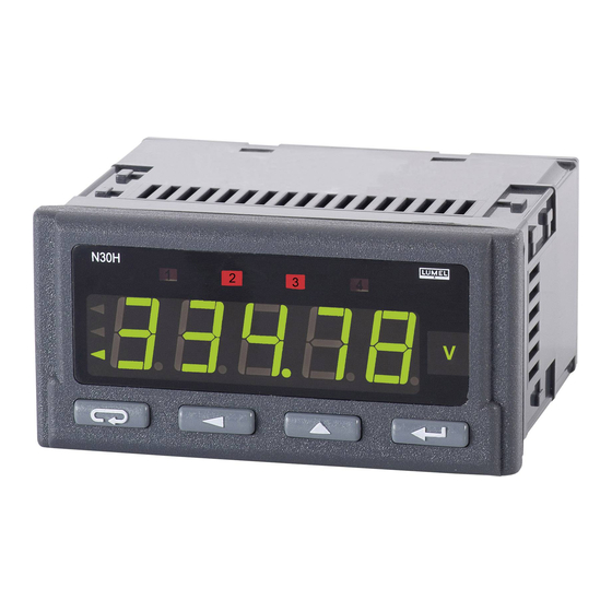
3. OBS£UGA 3.1. Opis wyświetlacza Rys. 6. Opis płyty czołowej miernika 3.2. Komunikaty po włączeniu zasilania Po włączeniu zasilania miernik wyświetla nazwę miernika N30-H, a na- stępnie wersję programu w postaci x.xx – gdzie x.xx jest numerem aktu- alnej wersji programu lub numerem wykonania specjalnego. Następnie miernik dokonuje pomiarów i wyświetla wartość... - Page 5 Þ wejście w tryb zmiany wartości parametru, Þ zaakceptowanie zmienionej wartości parametru, Þ zatrzymanie pomiaru – podczas trzymania przycisku wynik na wyświetlaczu nie jest aktualizowany. Pomiar jest nadal wykonywany. Þ włączenie zasilania miernika z przytrzymanym przyciskiem – wejście w tryb aktualizacji oprogramowania przez interfejs RS-485, parametry łącza: prędkość...
- Page 6 Wciśnięcie i przytrzymanie około 3 sekund przycisku powoduje wejście do matrycy programowania. Matryca programowania może zo- stać zabezpieczona kodem bezpieczeństwa. Wciśnięcie i przytrzymanie przez około 3 sekundy przycisku powoduje wejście do menu podglądu parametrów miernika. Po menu podglądu należy poruszać się za pomocą przycisku W menu tym dostępne są...
- Page 8 3.4. Programowanie Naciśnięcie przycisku i przytrzymanie go przez około 3 se- kundy powoduje wejście do matrycy programowania. Jeżeli wejście jest zabezpieczone hasłem wówczas jest wyświetlony symbol kodu bezpieczeństwa SEC na przemian z ustawioną wartością 0. Wpisanie poprawnego kodu powoduje wejście do matrycy, wpisanie błędnego kodu powoduje wyświetlenie napisu ErCod.
- Page 9 Rys. 8. Matryca programowania...
-
Page 10: Dane Techniczne
W celu zaakceptowania nastawionego parametru należy wcisnąć przy- cisk . Nastąpi wtedy zapisanie parametru i wyświetlanie jego symbolu na przemian z nową wartością. Wciśnięcie przycisku w trakcie zmiany wartości parametru spowoduje zrezygnowanie z za- pisu. 3.4.2 Zmiana wartości zmiennoprzecinkowych Zmiana wykonywana jest w 2 etapach (przejście do następnego etapu następuje po wciśnięciu przycisku 1) ustawienie wartości z zakresu -19999...99999 analogicznie jak dla wartości całkowitych;... - Page 11 Wyjścia analogowe (opcja): - programowalne prądowe 0/4...20 mA Rezystancja obciążenia £ 500 W - programowalne napięciowe 0..10; Rezystancja obciążenia ³ 500 W Wyjście alarmowe OC (opcja): Wyjście typu OC pasywne, npn. 30 V d.c./30 mA. Interfejs szeregowy: RS-485 (opcja) Protokół transmisji: MODBUS RTU Błąd wyjścia analogowego: 0,2% zakresu ustawionego.
-
Page 12: Basic Requirements, Operational Safety
1. BASIC REQUIREMENTS, OPERATIONAL SAFETY In the safety service scope, the N30H meter meets the requirements of the EN 61010-1 standard. Mentioned below applied symbols mean: - especially important, one must acquaint with this information before connecting the meter. The non-observance of notices marked by this symbol can occasion injures of the personnel and a damage of the instrument. -
Page 13: Installation
2. INSTALLATION The meter has separable strips with screw terminals, which enable the connection of external wires of 2.5 mm cross-section. Strips of input sig- nals are protected against any accidental disconnection by means of a screw joint. ´ 45 One must prepare a hole of 92 +0,6 +0,6... -
Page 14: Display Description
3.2. Messages after Switching the Supply on After switching the supply on, the meter displays the meter name N30H, and next the program version in the form „r x.xx” – where x.xx is the number of the current program version or the number of a custom-made execution. - Page 15 Þ Turning on the power supply of the meter while holding the button – entering the software-update mode through RS485 interface - Push-button increasing the value: Þ display of maximal value, The pressure of the push-button causes the display of the maximal value during ca 3 seconds. Þ...
- Page 16 One must move through the monitoring menu by means of push-buttons. In this menu, all programmable meter parame- ters are available only for readout. In this mode, the menu Ser is not available. The exit from the monitoring menu is carried out by means of push-button.
- Page 18 3.4. Programming The pressure of the push-button and holding it down through ca 3 seconds causes the entry to the programming matrix. If the entry is protected by a password, then the safety code symbol SEC is display- ed alternately with the set value 0. The write of the correct code causes the entry to the matrix, the write of an incorrect code causes the display of the ErCod inscription.
- Page 19 Fig. 8. Programming Matrix.
-
Page 20: Technical Data
3.4.2. Changing Floating-point Values The change is carried out in two stages ( the transition to the next stage follows after pressing the push-button: 1) setting values from the range -19999M...99999, similarly as for integral values; 2) setting decimal point positions (00000., 0000.0, 000.00, 00.000, 0.0000);... - Page 21 Serial interface: RS-485 (option) Transmission protocol: MODBUS RTU Error of analog output: 0.2% of the set range. Protection grade ensured by the casing: frontal side IP65, terminal side IP10 Weight: < 0.2 kg, Dimensions: 96 ´ 48 ´ 93 mm Reference Conditions and Rated Operating conditions: - supply voltage: 85..253 V d.c./a.c.
- Page 22 schematy podłączeń electrical connections 4.1. Wyprowadzenia sygnałów Na rys. 3. przedstawiono sygnały wyprowadzone na złącza miernika. Wszystkie sygnały wejściowe są odseparowane od pozostałych obwo- dów. Wejścia analogowe nie są separowane między sobą. Nie należy korzystać jednocześnie z pomiaru napięcia i prądu, gdyż obwody pomiarowe napięcia i prądu nie są...
-
Page 23: Examples Of Connections
4.2. Examples of Connections An example of the N30H meter connection for current measurement is presented on the fig. 4.However, an example of the meter connection in the configuration for voltage measurement is presented on the fig. 5. - Page 24 LUMEL S.A. ul. Słubicka 4, 65-127 Zielona Góra, Poland tel.: +48 68 45 75 100, fax +48 68 45 75 508 www.lumel.com.pl Informacja techniczna: tel.: (68) 45 75 140, 45 75 141, 45 75 142, 45 75 145, 45 75 146 e-mail: sprzedaz@lumel.com.pl...
Need help?
Do you have a question about the N30H and is the answer not in the manual?
Questions and answers