Advertisement
For complete technical information about this product, including dimensions, accessories, and specifications, see www.datalogic.com.
WARNING: Not to be used for personnel protection
Never use this device as a sensing device for personnel protection.
Doing so could lead to serious injury or death. This device does not include the self-checking redundant circuitry
necessary to allow its use in personnel safety applications.
A sensor failure or malfunction can cause either an energized or de-energized sensor output condition.
Model
S70-5-E3-PV/NV
S70-5-E3-PI/NI
1
NOTE: Maximum sensing range in opposed mode at 12 ms response speed using 1mm diameter core plastic fiber.
CONNECTIONS
NPN Version
1
3
A_Out
2
LOAD
D_Out
4
LOAD
NOTE: Open lead wires must be connected to a terminal block.
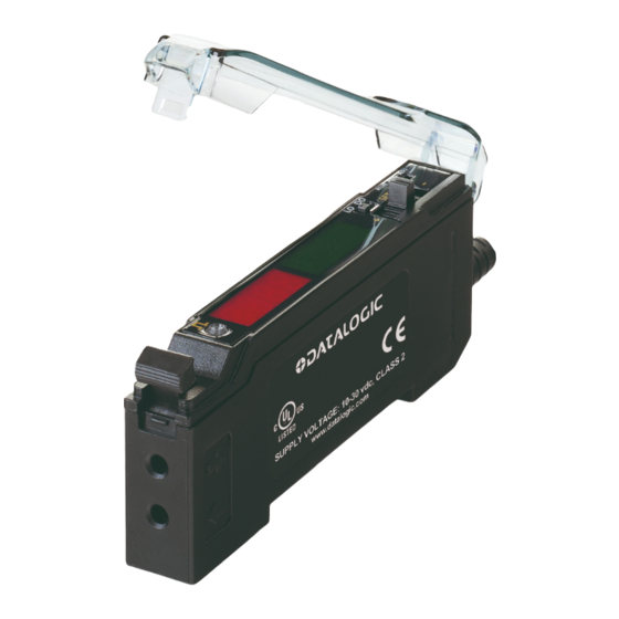
S70 Analogue Output
Advanced sensor with dual digital displays
for use with plastic and glass fiber optic assemblies
Figure 1
Sensing Beam Color Reference Sensing Range
Visible Red
+
10-30 VDC (Current models)
12-30 VDC (Voltage models)
Input wire
1
2
3
4
5
6
7
1
Outputs
Voltage and PNP or
Discrete
2250 mm
Current and PNP or
Discrete
PNP Version
1
10-30 VDC (Current models)
3
12-30 VDC (Voltage models)
A_Out
2
LOAD
D_Out
4
LOAD
Input wire
1
Analogue and Discrete Output LEDs
CH1/CH2 Switch
RUN/PRG/ADJ Mode Switch
Lever Action Fiber Clamp
Red Signal Level
Green CH1 Analog Output
Signal or CH2 Threshold
+/SET/- Navigation key
Connector
NPN
4-pin,
M8 Pico-style
NPN
Key
1 = Brown
+
2 = White
3 = Blue
4 = Black
Advertisement
Table of Contents

Related Manuals for Datalogic S70


Summary of Contents for Datalogic S70
- Page 1 S70 Analogue Output Advanced sensor with dual digital displays for use with plastic and glass fiber optic assemblies For complete technical information about this product, including dimensions, accessories, and specifications, see www.datalogic.com. Analogue and Discrete Output LEDs CH1/CH2 Switch RUN/PRG/ADJ Mode Switch...
-
Page 2: Mounting Instructions
MOUNTING INSTRUCTIONS Mount on a DIN Rail 1. Hook the DIN rail clip on the bottom of the S70 over the edge of the DIN rail (1). 2. Push the S70 up on the DIN rail (1). 3. Pivot the S70 onto the DIN rail, pressing until it snaps into place (2). -
Page 3: Top Panel Interface
2 represents the Channel 2 discrete output. When on, it indicates that the output is conducting. Teach / Set methods For more information about how to perform TEACH/SET methods, see the www.datalogic.com. Run Mode Run mode allows the sensor to operate normally and prevents unintentional programming changes. - Page 4 Press and hold SET to exit Program (PRG) mode allows the choice list without saving following settings to be programmed in the S70. CH1 Analog Factory Default Settings: NOTE: The CH1 settings programmed for rESP SPd, inPt SEL, diSP rEAd and...
- Page 5 Channel 2 Discrete Menu Program (PRG) mode allows the following settings to be programmed in the S70. When CH2 is selected in Program mode, the settings below can be configured for CH2 discrete output and are independent from CH1 settings.
- Page 6 ADJUST MODE Sliding the RUN/PRG/ADJ mode switch to the ADJ position allows the user to perform Expert TEACH/SET methods and Manual Adjustment of the threshold and the midpoint or endpoints of the analogue output depending on whether a 1-point SET or 2-point TEACH was used. NOTE: For threshold and analogue endpoints, when teaching CH2, the gain setting will be the same as the gain setting made during the CH1 teach.
- Page 7 CH2 Discrete Output - Two-Point TEACH • Establishes a single switching threshold • Threshold can be adjusted by using the "+" and "-" Navigation key (Manual Adjust) Two-Point TEACH is used when two conditions can be presented statically to the sensor. The sensor locates a single sensing threshold (the switch point) midway between the two taught conditions, with the Output ON condition on one side, and the Output OFF condition on the other.
- Page 8 - Light SET • Sets a threshold a programmable % offset below the presented condition • Changes output state on any condition darker than the threshold condition • Threshold can be adjusted using "+" and "-" Navigation key (Manual Adjust) •...
-
Page 9: Technical Data
TECHNICAL DATA Sensing Beam: Visible red, 635 nm Voltage output models: 12 to 30 VDC Class 2 (10% maximum ripple) Supply Voltage: Current output models: 10 to 30 VDC Class 2 (10% maximum ripple) Power and Current Consumption Standard display mode: 840 mW, Current consumption <... -
Page 10: Overall Dimensions
Datalogic S.r.l. Via S. Vitalino 13 - 40012 Calderara di Reno - Italy Tel: +39 051 3147011 - Fax: +39 051 3147205 - www.datalogic.com Datalogic reserves the right to make modifications and improvements without prior notification. 821005061 Rev. A November 2017...
Need help?
Do you have a question about the S70 and is the answer not in the manual?
Questions and answers