Chauvet Professional Ground Support 2 Kit User Manual
Hide thumbs
Also See for Ground Support 2 Kit:
- Quick reference manual (12 pages) ,
- Quick reference manual (64 pages)
Table of Contents
Advertisement
Quick Links
Advertisement
Table of Contents

Related Manuals for Chauvet Professional Ground Support 2 Kit


Summary of Contents for Chauvet Professional Ground Support 2 Kit
- Page 1 User Manual Model ID: GROUNDSUPPORT2KIT...
- Page 2 Edition Notes The Ground Support 2 Kit User Manual includes a description, safety precautions, installation, programming, operation and maintenance instructions for the Ground Support 2 Kit as of the release date of this edition. Trademarks CHAUVET, the Chauvet logo and Ground Support 2 Kit are registered trademarks or trademarks of Chauvet &...
-
Page 3: Table Of Contents
Installing on F-Series Panels ..................23 VID-CURVEKIT Mounting ....................24 VID-CURVEKIT Mounting Diagram ................VID-CURVEKIT Mounting Procedure ................Curved Setup Example ....................25 5. Maintenance....................Lubrication........................ Inspecting for Faults....................6. Technical Specifications................Returns ......................Contact Us......................Ground Support 2 Kit User Manual Rev. 1... -
Page 4: Before You Begin
• Quick Reference Guide clips (x6) The Ground Support 2 Kit is shipped in the road case. Claims Carefully unpack the product immediately and check the container to make sure all the parts are in the package and are in good condition. -
Page 5: Introduction
The Ground Support 2 Kit is a complete ground support solution for stacking F-series video panels as a video wall on the floor. Multiple kits can be used to stack wider video walls. The Ground Support 2 Kit can accommodate flat and concave video walls, including a 5° or 10° curve (kit sold separately). The DRB- F100CM or DRB-F50CM dual function rig bars are required for operation. -
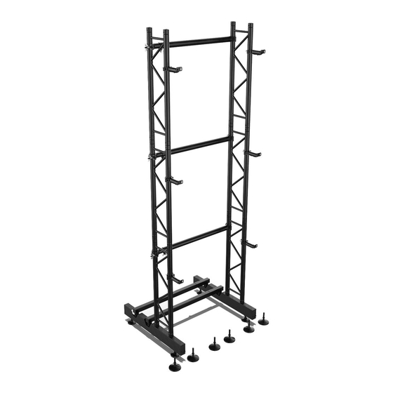
Page 6: Assembled Product Dimensions
Tightening nut Floor Base Overview Coupler spigot, pin, and Anchor for angling horizontal bar safety clip for ladder truss Male speego connection TR16 screw jack for dual-function rig bar Page 3 of 29 Ground Support 2 Kit User Manual Rev. 1... -
Page 7: Angling Horizontal Bar Overview
Angling 1M Pipe Overview Tightening wing-nuts Adjustable end clamp Fixed end clamp Minimum supported angling 1M pipe length: 1 m Maximum supported angling 1M pipe length: 1.27 m Ground Support 2 Kit User Manual Rev. 1 Page 4 of 29... -
Page 8: Panel Attachment Arm Overview
Anchor for panel attachment screws Minimum panel attachment arm length: 0.22 m Maximum panel attachment arm length: 0.27 m Accessories Overview Safety Coupler Panel attachment spigot clip screw Page 5 of 29 Ground Support 2 Kit User Manual Rev. 1... -
Page 9: Setup
Rubber mallet Unpacking The Ground Support 2 Kit comes in a road case, with all parts and pieces fitted in securely. Follow the steps below to unpack the road case and verify that all parts and pieces are within. 1. Open the road case. - Page 10 Panel attachment arms (6) • TR16 screw jacks (6) Spigot (x12) Pins and safety clips (x16) Panel attachment Panel attachment TR16 screw jack screws (x12) arm (x6) (x6) Page 7 of 29 Ground Support 2 Kit User Manual Rev. 1...
-
Page 11: Setup Procedure
Plan correctly for the type of setup to be created! 1. Insert TR16 screw jacks into their corresponding threaded holes on the bottom of the dual-function rig bar (DRB-F50CM or DRB-F100CM; not included with the Ground Support 2 Kit). Threaded holes for TR16 screw jacks Ground Support 2 Kit User Manual Rev. - Page 12 Warning! If the rig bars and floor bases are not completely level, the Ground Support 2 Kit may be unstable, lean forward or backwards, or collapse. This may cause severe damage to equipment, products, flooring, or people! 4.
- Page 13 Each pin can only go through each coupler spigot in one direction. Use a rubber mallet to get the pins fully through the spigots if necessary. Ground Support 2 Kit User Manual Rev. 1 Page 10 of 29...
- Page 14 13. Attach the clamp on the adjustable end of the angling 1M pipe to the paired ladder truss. Tightening wing-nuts 14. Verify that the angling 1M pipe is level with a bubble level tool, then tighten the wing-nuts. Page 11 of 29 Ground Support 2 Kit User Manual Rev. 1...
- Page 15 Setup 15. Place ballast weights (sandbags or steel weights) evenly over the angling horizontal bars. Example sandbag placement Ground Support 2 Kit User Manual Rev. 1 Page 12 of 29...
-
Page 16: Ballast Weight Requirements
48.07 in 1.97 in 1270 mm 50 mm 13.58 in 345 mm 3.54 in 1.57 in 6.1 in 0.63 in 155 mm 16 mm 90 mm 40 mm Page 13 of 29 Ground Support 2 Kit User Manual Rev. 1... -
Page 17: Drb-Curvekit Instructions
To create a curved video wall with the Ground Support 2 Kit, The VID-CURVEKIT and DRB-CURVEKIT must both be used. To set up the Ground Support 2 Kit with a 5° or 10° concave curve, connect the dual function rig bars with the DRB-CURVEKIT. -
Page 18: Installing The Angling Horizontal Bars With The Drb-Curvekit
Otherwise, the VID-CURVEKIT will not be able to be used in alignment with the DRB-CURVEKIT, and the panels will not be able to be mounted. Page 15 of 29 Ground Support 2 Kit User Manual Rev. 1... -
Page 19: Mounting
This chapter explains the methods for mounting F-series video panels (or Vivid panels) to the Ground Support 2 Kit. The specific method required depends on the video panels being mounted, and whether or not the VID-CURVEKIT and DRB-CURVEKIT are being used. - Page 20 If the attachment arm is connected to the center mounting position, it will need to be extended to the third locking level. 4. Secure the clamp of the panel attachment arm to the ladder truss. Page 17 of 29 Ground Support 2 Kit User Manual Rev. 1...
- Page 21 Combine additional Ground Support 2 Kits to achieve wider walls. Warning! If the rig bars and floor bases are not completely level, the Ground Support 2 Kit may be unstable, lean forward or backwards, or collapse. This may cause severe damage to equipment, products, flooring, or people! Ground Support 2 Kit User Manual Rev.
-
Page 22: Mounting Procedure (Corner)
Both the F4IP and Vivid 4 have been upgraded with center mounting position frames, and may vary depending on order date. Page 19 of 29 Ground Support 2 Kit User Manual Rev. 1... - Page 23 When using the corner mounting positions to secure video panels to the Ground Support 2 Kit, only one slot of the panel attachment arm should be used. 4. Secure the clamp of the panel attachment arm to the ladder truss.
- Page 24 Combine additional Ground Support 2 Kits to achieve wider walls. Warning! If the rig bars and floor bases are not completely level, the Ground Support 2 Kit may be unstable, lean forward or backwards, or collapse. This may cause severe damage...
-
Page 25: Mounting Procedure (Vid-Curvekit)
Mounting Mounting Procedure (VID-CURVEKIT) If the Ground Support 2 Kit was set up with the DRB-CURVEKIT (see DRB-CURVEKIT Instructions), then the F-series video panels will need to be connected horizontally with the VID-CURVEKIT at every corresponding point. Download the Quick Reference Guide for the VID-CURVEKIT from www.chauvetprofessional.com... -
Page 26: Installing On F-Series Panels
To install the VID-CURVEKIT on an F-Series video panel, screw the M12 33 mm screws through the lock washers, through the brackets, and into the M12 mounting points on the panel as indicated below. M12 33 mm Screw Top Male Bracket Lock Washer F-Series Panel Page 23 of 29 Ground Support 2 Kit User Manual Rev. 1... -
Page 27: Vid-Curvekit Mounting
4. Twist the tightening latch clockwise until the male bracket is secure to the female bracket. 5. To detach the VID-CURVEKIT brackets and separate the F-Series panels, reverse the previous steps. Ground Support 2 Kit User Manual Rev. 1 Page 24 of 29... -
Page 28: Curved Setup Example
*Ballast weights not shown for illustrative purposes only. A single 10° curve or a pair of 5° curves can be used within each Ground Support 2 Kit. *Ballast weights not shown for illustrative purposes only. The ballast weights MUST always be in position before installing any panels, or any Ground Support 2 Kit setup taller than 1 meter. -
Page 29: Maintenance
Screw jacks Inspecting for Faults Each part of the Ground Support 2 Kit should be regularly inspected for faults such as warping or cracking. A qualified and competent person should inspect the product for faults before each use to ensure it performs as intended. -
Page 30: Technical Specifications
4.92 ft (1.5 m) 8.2 ft (2.5 m) Note: Dimensions in inches are rounded. Ordering Product Name Item Name Item Code UPC Number Ground Support 2 Kit GROUNDSUPPORT2KIT 23091609 781462219574 Page 27 of 29 Ground Support 2 Kit User Manual Rev. 1... -
Page 31: Returns
Be sure to pack the product properly. Any shipping damage resulting from inadequate packaging will be your responsibility. FedEx packing or double-boxing are recommended. Chauvet reserves the right to use its own discretion to repair or replace returned product(s). Ground Support 2 Kit User Manual Rev. 1 Page 28 of 29... -
Page 32: Contact Us
Visit the applicable website above to verify our contact information and instructions to request support. Outside the U.S., U.K., Ireland, Benelux, France, Germany, or Mexico, contact the dealer of record. Page 29 of 29 Ground Support 2 Kit User Manual Rev. 1...
Need help?
Do you have a question about the Ground Support 2 Kit and is the answer not in the manual?
Questions and answers