
Related Manuals for Wood-mizer LX55


Summary of Contents for Wood-mizer LX55
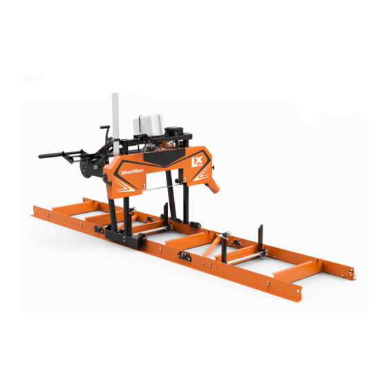
- Page 1 LX55 Sawmill Safety, Operation, & Maintenance Manual LX55G14 rev. A1.00 LX55G9 rev. A1.00 LX55E7 rev. A1.00 Safety is our #1 concern! September 2019 Form #2398 WARNING! Read and understand this manual before using this machine.
- Page 2 Active Patents assigned to Wood-Mizer, LLC Belzile, Luc. 2016. Portable saw mill with bed adjustments. US Patent US 9,352,480B, filed Sepember 11, 2012, and issued May 31, 2016. Belzile, Luc. 2019. Blade sharpening and setting system. US Patent US10315260B2, filed August 27, 206, and issued June 11.
-
Page 3: Table Of Contents
INTRODUCTION About This Manual.................1-1 Getting Service ..................1-1 General Contact Information..........1-1 Warranty ....................1-2 Customer and Sawmill Identification.............1-5 LX55 Specifications ................1-6 SAFETY Safety Symbols..................2-1 Safety Instructions ..................2-1 Observe ALL Safety Instructions...........2-1 Wear Safety Clothing (Personal Protection Equipment) ..2-2 Keep Work Area Clean ............2-3 Fuel/Flammable Liquid Handling Safety......2-3... - Page 4 5.11 Transporting the Sawmill ...............5-9 MAINTENANCE Blade Guides ..................6-1 Sawdust removal ..................6-1 General Maintenance................6-1 Every 8 Hours of Sawmill Operation (Daily) .......6-1 Every 160 Hours of Sawmill Operation (Monthly)....6-2 As Needed .................6-3 Motor/Engine Maintenance ..............6-3 LX55 9/17/20 Table of Contents...
-
Page 5: Introduction
About This Manual SECTION 1 INTRODUCTION LX55 About This Manual This manual replaces any previous information received on your Wood-Mizer ® equipment. The information and instructions in this manual do not amend or extend the limited warranties for the equipment given at the time of purchase. -
Page 6: Warranty
Wood-Mizer Limited Product Warranty Wood-Mizer LLC (“Warrantor”), an Indiana corporation with its principal place of business at 8180 West Tenth Street, Indianapolis, IN 46214-2400 USA, warrants to the purchaser (“Purchaser”) that for the time periods specifically stated herein and subject to the terms, conditions and limitations stated herein, the equipment manufactured by the Warrantor... - Page 7 FIVE YEAR LIMITED CHASSIS WARRANTY The limited five year chassis warranty, described above, DOES NOT extend to (a) any damage stemming from acci- dent, improper towing, overload, abuse, misuse, abnormal conditions, negligence, excessive operation, or lack of Introduction LX55 9/17/20...
- Page 8 This warranty cannot be amended, except in writing, which refers to this warranty that is signed by both Warrantor and Purchaser. © 2018 Wood-Mizer LLC – 8180 West 10 Street, Indianapolis, IN 46214...
-
Page 9: Customer And Sawmill Identification
Customer and Sawmill Identification Customer and Sawmill Identification Each Wood-Mizer sawmill is identified with a model number, revision, and serial number (see the figure below). M FG B Y / FA B R IQ U É PA R : W O O D -M IZ ER P R O D U C TS , IN C . 8 18 0 W. 1 0th St. Ind ian ap olis , 4 62 1 4 -2 40 0 U .S .A . -
Page 10: Lx55 Specifications
LX55 Specifications LX55 Specifications DIMENSIONS LX55 9/17/20... -
Page 11: Safety
The procedures listed in this manual may not include all ANSI, OSHA, or locally required safety procedures. It is the owner/operator’s responsibility and not Wood-Mizer LLC to ensure all operators are properly trained and informed of all safety protocols. Owner/Operators are responsible for following all safety procedures when operating and performing maintenance to the equipment. -
Page 12: Wear Safety Clothing (Personal Protection Equipment)
Keep all other persons away from area when coiling, carrying, or chang- ing a blade. Some woods require respiration protection when operating the sawmill. It is the sawyer’s respon- sibility to know which woods require respira- tion protection. LX55 9/17/20 Safety... -
Page 13: Keep Work Area Clean
Do not use flammable liquids (diesel fuel or kerosene) in the water lube accessories. Clean fuel/flammable liquid spills immediately. NOTICE Remove blades from equipment before cleaning them with fuel/flammable liquid. Dispose of fuel/flammable liquids per local ordinances. Safety LX55 9/17/20... -
Page 14: Battery Safety
INHALATION Sulfuric Acid: Remove to fresh air immediately. If not breathing, give artificial respiration. If breathing is difficult, give oxygen. Consult a physician. Lead: Remove from exposure, gargle, wash nose and lips; consult physician. LX55 9/17/20 Safety... -
Page 15: Sawmill Setup Safety
Use a lifting device (fork lift, crane, etc.) for parts over 100 lbs. Use two persons for lifting parts over 50lbs. Keep all non-essential personnel out of the area while set- ting up the sawmill. 1.For more information on lifting safety see NOISH Lifting Equation at https://www.cdc.gov/niosh/docs/94‐110/ Safety LX55 9/17/20... -
Page 16: Safety Decals
Observe all safety instruc- tions and rules when operating the mill. 096319 Disconnect Power Supply Before Opening (Electric version only) 096321 Blade Movement Direction 099220 Sawmill Covers Caution CAUTION! Close all guards and cov- ers before starting the machine. LX55 9/17/20 Safety... - Page 17 Align the disc in the notch for proper blade tension. P11789 Blade Alignment Turn counterclockwise to raise the blade. Turn clockwise to lower the blade. 501465 Use Safety Boots Wear protective boots at all times when operating the mill! Safety LX55 9/17/20...
- Page 18 Safety Safety Decals S12004g Use Eye Protection Wear safety goggles at all times when operating the mill! S12005g Use Ear Protection Wear ear protection at all times when operating the mill! LX55 9/17/20 Safety...
-
Page 19: Assembly 3.1 Unpack The Mill
Clear the area. Inspect the site for debris or uneven surfaces that may become a trip hazard. Clear out all non-essential personnel. Gas mills Do not set up in enclose areas. Assembly LX55 9/17/20... -
Page 20: Torque Settings
1. Insert the upper mast tube into the mast leg brackets. See Fig. 3-1. 2. Align the scale mount bracket with the upper mast tube and the right mast leg. 3. Retrieve the hardware from the Mast Kit bag. LX55 9/17/20 Assembly... - Page 21 6. Insert the head locking pins to prevent the head from sliding off the mast. See Fig. 3-2. Mast guides are shipped loose. Do not tighten at this time! Locking Pins NOTE: Position the sawhead on a bench/flat surface at least 24” (0.6m) off of the ground. 55001-14 FIG. 3-2 Assembly LX55 9/17/20...
-
Page 22: Assemble The Log Bed
NOTE: Do not assemble more on the carriage until later steps are com- pleted. Assemble the Log Bed The bed should be assembled on its operation site. NOTE: Do not assembly the catch rail to the bed until after the carriage has been placed on it. LX55 9/17/20 Assembly... -
Page 23: Assemble The Bed Sections
3. Tighten all bolts on the tab side of the cross rails. 4. Adjust the track and cross rails (if needed) to square them. 5. Tighten all bolts. OPTIONAL LEVELING FEET Install the optional leveling feet as shown in Fig. 3-5. FIG. 3-5 Assembly LX55 9/17/20... -
Page 24: Assemble The Connector Plates
Ensure that the top of the rail joints are smooth. f. Tighten the bolts in the slotted holes. 2. Assemble the cross braces, tightening the M10x30mm bolts. See Fig. 3-7. Bolt, M10x30mm, Class 8 Washer, M10 Flat Nut, M10 Flanged Nylon Lock 55001-10 FIG. 3-7 LX55 9/17/20 Assembly... -
Page 25: Assemble The Log Clamps
Nylon Lock Bolt, M10x20mm, Clamp Screw Class 8 Clamp Point 55001-36 Bolt, M6x50mm Washer, M10 Flat Class 8.8 FIG. 3-8 3. Install the mounting brackets to the rod with M10x20mm bolts. 4. Insert the side support adjustment hardware. Assembly LX55 9/17/20... -
Page 26: Stop Blocks Installation
Secure the Sawhead Carriage. WARNING! Failure to install stop blocks may result in serious personal injury and/or machine damage. Securing pin Nut, M10 Flanged Nylon Lock Washer, M10 Flat Bolt, M10x30mm, Class 8 FIG. 3-10 LX55 9/17/20 Assembly... -
Page 27: Bed Leveling
1. Loosen the horizontal bearings on the roller assemblies. Bearing holes are slotted Horizontal bearings 55001-16 FIG. 3-12 2. Place the carriage assembly on the sawmill bed. 3. Ensure that the vertical track roller bearings sit properly on the track rail. Assembly LX55 9/17/20... -
Page 28: Assemble Catch Rail
6. Adjust the track wiper so that the felt touches the track rail surface and the sawhead moves freely on the bed. See Fig. 3-13. Track Wiper Felt FIG. 3-13 Assemble Catch Rail The catch rail may be assembled on either side, but installing on the dust chute side makes load- ing logs easier. 3-10 LX55 9/17/20 Assembly... -
Page 29: Secure The Sawhead Carriage
Nylon Lock Washer, M10 Flat 55001-33 FIG. 3-14 Secure the Sawhead Carriage At the head of the log bed secure the carriage with a locking pin to prevent accidental movement. See Fig. 3-15. 55001-15 FIG. 3-15 Assembly LX55 9/17/20 3-11... -
Page 30: Tension Tool, Latch, And Sawdust Chute Assembly
Bolt, M6x16mm 55001-27 FIG. 3-17 Install the Engine (Gas Versions Only) 1. Unpack the engine and its parts. 2. Set the engine on the engine mounting platform and loosely secure with M10x50mm bolts. See Fig. 3-18. 3-12 LX55 9/17/20 Assembly... - Page 31 7. Ensure the bushing is flush to the end of the shaft. See Fig. 3-20. 8. Tighten the bushing set screw with a 3mm hex wrench. See Fig. 3-20. 9. Set the pulley over the bushing. Assembly LX55 9/17/20 3-13...
- Page 32 NOTE: Some engines are shipped with the throttle lever tight. If necessary, loosen the throttle lever by loosening the nut at the top. 55007-3-1 14. Place the drive belt around the drive pulley. 15. Tighten all mounting bolts. 3-14 LX55 9/17/20 Assembly...
-
Page 33: Install The Motor (Electric Version Only)
6. Set the pulley over the bushing. 7. Secure the pulley with the bushing bolts. See Fig. 3-23 Set bushing flush with shaft Set screw Bushing bolt Bushing Pulley 550015-02 FIG. 3-23 8. Tighten motor mount bolts. 9. Place belt over pulley. Assembly LX55 9/17/20 3-15... - Page 34 Washer, M8 Flat 550015-03 FIG. 3-24 11. Adjust the tension rod nuts until the rod threads show about 2-5/8" (67mm) between the bottom of the rod head and the mounting bracket. See Fig. 3-24. 12. Tighten all nuts. 3-16 LX55 9/17/20 Assembly...
-
Page 35: 3.10 Finish Carriage Assembly
3. Glide the carriage along the log bed to ensure that rollers move smoothly. NOTE: If the carriage does not ride smoothly, recheck the bed section joints or how the bearings sit on the rail. Assembly LX55 9/17/20 3-17... -
Page 36: Push Handle
2. Slide the grip over the end of the push handle; use a lubricant, if necessary. Control box and mount M6x20mm Capscrew, ELECTRIC VERSION ONLY Nut, M8 Flanged Nylon Lock Grip Washer, M8 Flat M8x75mm 550015-04 Bolt, FIG. 3-26 3-18 LX55 9/17/20 Assembly... -
Page 37: Mount Lift System
3. Tighten the sprocket set screw. (See inset of Fig. 3-29.) 4. Attach the shaft ends. NOTICE The helical shaft ends are left-right oriented according to the direction of the spiral. Ensure that the spiral directs the lift cable to the Assembly LX55 9/17/20 3-19... - Page 38 5. Align the helical shaft ends over the through-holes and set screw holes in the shaft ends. 6. Slightly tighten the set screws to maintain that alignment. (Set screw will be fully tightened when the cable is inserted.) 3-20 LX55 9/17/20 Assembly...
- Page 39 3. Insert the sprocket through the bushing and screw on the handle plate; fasten with the M12 nut. 4. Place the chain around the large sprocket on the shaft 5. Assemble the master link in the adjustment chain 6. Place the chain around the small sprocket. Assembly LX55 9/17/20 3-21...
- Page 40 Start with this bolt! Spacer Bolt, M8x50mm, Carriage 55001-21-5 FIG. 3-31 1. Place the carriage bolts through the adjustment plate. See Fig. 3-31. 2. Slide the spacers on the carriage bolts. 3. Tighten the nuts on the carriage bolts. 3-22 LX55 9/17/20 Assembly...
- Page 41 Washer, M8 Flat ROUTE Lift Cable Nut, M8 Bolt, M8 10-12mm Spacer Roller 55001-24 Shoulder FIG. 3-32 WARNING! Use assistance in lowering the sawhead. Avoid injury and equipment damage. 2. Tighten the lower mast guides on both sides. Assembly LX55 9/17/20 3-23...
- Page 42 8. Thread the lift cable through the hole in the lift shaft ends until all slack is taken up. 9. Tighten the set screw when the cable is tensioned. 10. Repeat on the other side of the sawhead. 11. Raise and lower the sawhead to check for additional adjustments. 3-24 LX55 9/17/20 Assembly...
-
Page 43: Clutch Lever Installation (Gas Versions Only)
4. Route the cable through the sawhead grommets and attach it to the clutch. See Fig. 3-35. Throttle cable Clutch cable in center position Clutch cable Tighten nut 550011 550014 FIG. 3-35 See Section 4.8 for information on cable adjustment. Assembly LX55 9/17/20 3-25... -
Page 44: 3.12 Water Bottle Installation
1. Apply scale decal 3/4” down from the top of the height scale bracket (if not pre-applied). 2. Open the sawhead cover to install the blade height scale bracket. 3. Use M8x20mm carriage bolts to attach blade height scale to the sawhead cover. See Fig. 3-37. 3-26 LX55 9/17/20 Assembly... -
Page 45: 3.14 Install The Blade
Changing blades is safest when done by one person. Failure to follow this may result in serious injury. 1. Watch the video on sawmill blades before removing the blade from the box. NOTE: Do not remove the blade from the shipping box at this time. Assembly LX55 9/17/20 3-27... - Page 46 3. Open the blade housing cover. 4. Turn the blade tension bar with the ratchet until the blade wheel is moved in. See Fig. 3-38 55001 FIG. 3-38 5. Carefully remove and uncoil the blade from the shipping box. 3-28 LX55 9/17/20 Assembly...
- Page 47 7. Position 1 1/4” wide blades (standard) on the wheels so the gullet is 1/8" (3.0 mm) out from the edge of the wheel. See Fig. 3-40. 150060 1/8” (3.0 mm) ± 1/32” (0.75 mm) 1 1/4” Blade FIG. 3-40 Go directly to the Section 4, Alignment to align it before use. Assembly LX55 9/17/20 3-29...
-
Page 48: Alignment
2. Start the engine/motor. NOTICE See the appropriate manual supplied with your specific engine/motor configuration for starting and operating instructions. 3. Engage the blade momentarily, rotating the blade until the blade positions itself on the wheels. 4. Disengage the blade. LX55 9/17/20 Alignment... - Page 49 If the blade is too far in, turn the cant control clockwise until the gullet of the blade is the correct distance from the front edge of the wheel. See Fig. 4-2. 7. Repeat these steps until the blade tracks properly on the blade wheels. Alignment LX55 9/17/20...
-
Page 50: Squaring The Sawblade
6. If the two measurements differ by more than 1/16" (1.5 mm), adjust the vertical tilt of the drive-side blade wheel. 7. Use the screws shown in Fig. 4-5 to adjust the drive blade wheel vertically. a. Loosen the jam nut on the bottom adjustment screw and tighten the screw. LX55 9/17/20 Alignment... -
Page 51: Saw Head Adjustment
1. Check that the tensioned blade is parallel to a bed rail. See Section 4.3. 2. Raise the sawhead approximately half way. 3. Measure the distance between the blade and the bed rail on both sides of the saw head. 4. Loosen the nylon mast guide. Alignment LX55 9/17/20... - Page 52 5. Move the threaded rod up or down by loosening the lower jam nut and tightening the upper nut until both measurements are the same. Threaded rod Jam nut 55001-13 FIG. 4-7 CAUTION! Do not to loosen the upper nut completely as it can cause the saw head to fall. 6. Tighten the mast guides. LX55 9/17/20 Alignment...
-
Page 53: Blade Deflection
The blade guides should be adjusted properly in the vertical plane. If the blade guides are tilted vertically, the blade will try to travel in the tilted direction. Use the Blade Guide Alignment Tool (LTBGAT) to measure the vertical tilt of the blade. Alignment LX55 9/17/20... - Page 54 Adjustment Screw Adjust screws down to tilt roller up; Adjust screws up to tilt roller down SM0310-1 Bottom Vertical Tilt Adjustment Screw FIG. 4-9 9. Loosen one set screw at the side of the blade guide assembly. LX55 9/17/20 Alignment...
-
Page 55: Blade Guide Flange Spacing
Contact with the trailing edge would force the blade upward onto the roller. NOTICE When adjusting blade guide spacing, loosen the top set screw and one side set screw only. This will ensure horizontal and verti- cal tilt adjustments are maintained when the adjustment screws are retightened. Alignment LX55 9/17/20... - Page 56 6. Ensure that the distance between the flange on the inner blade guide roller to the back edge of the blade measures to 1/16" (1.5 mm). See Figure 4-9. 7. Adjust the roller back or forward, as described above. 8. Check previous alignments and adjust as necessary. LX55 9/17/20 Alignment...
-
Page 57: Blade Height Scale Adjustment
The throttle cable is adjusted properly if the engine runs at full rotational speed (3600 r.p.m.) when the clutch handle is pushed down. When the clutch handle is released, the engine should return to idle and the drive pulley should stop spinning Alignment LX55 9/17/20 4-10... - Page 58 1. Adjust the drive belt by increasing or reducing the clutch cable. See Fig. 4-11. If necessary, adjust the throttle cable connecting the clutch with the engine throttle. . Clutch cable Throttle Cable 550011 FIG. 4-11 4-11 LX55 9/17/20 Alignment...
-
Page 59: Sawmill Operation
3. Raise the side supports on the sawmill bed to prevent the log from falling off the side of the bed. 4. Position the log parallel to the sawmill bed. 5. Roll the log onto the sawmill bed. NOTE: Use log loading equipment or a ramp to load the log onto the saw- mill bed. Sawmill Operation LX55 9/17/20... - Page 60 Make sure the side supports are positioned low enough for the blade to pass over them. If they are not, back the clamp off slightly and push the side supports down until they are positioned below the height of your last cut on a given side of the log. LX55 9/17/20 Sawmill Operation...
-
Page 61: Level A Log
FIG. 5-2 Lift Operation 1. Install a blade, if needed, and check for correct blade tension. 2. Use the crank handle to raise or lower the sawhead. 550012 Use crank handle to change sawhead height FIG. 5-3 Sawmill Operation LX55 9/17/20... -
Page 62: Gas Engine Operation
Cold engine: When the engine starts, slowly open the choke all the way by moving the choke lever to the “OFF” position. 6. Engage the clutch handle by pulling it toward you as shown in Fig.5-4 . Clutch Handle 55001-17 FIG. 5-4 LX55 9/17/20 Sawmill Operation... -
Page 63: Feed Operation
Adjust the outer blade guide to clear the widest section of the log by moving the blade guide arm knob. 4. Engage the clutch to start the blade spinning. 5. Start the water lube if necessary to prevent sap buildup on the blade. 6. Feed the blade into the log slowly. Sawmill Operation LX55 9/17/20... -
Page 64: Edging
5. Loosen the clamps and turn the edged boards over to edge the other side. 6. Repeat steps 2-4. 7. Loosen the clamps and remove the boards that have good clean edges on both sides. Clamp the remaining flitches and repeat steps 2-5. LX55 9/17/20 Sawmill Operation... -
Page 65: Blade Height Scale
Make a trim cut. Return the mast for the second cut and lower it 1 1/8" (29 mm) below the original measurement. (The extra 1/8" (3 mm) allows for saw kerf and shrinkage of the lumber.) Sawmill Operation LX55 9/17/20... -
Page 66: 5.10 Water Lube Operation
The Water Lube System keeps the blade clean. Water flows from a 5-gallon (18.9 liter) bottle through a hose to the blade guide where the blade enters the log. A valve in the bottle cap con- trols the amount of water flow. Normal flow is 1-2 gallons (3.8-7.6 liters) per hour. LX55 9/17/20 Sawmill Operation... -
Page 67: 5.11 Transporting The Sawmill
Keep all persons out of the path of the sawhead while loading and unload- ing the sawmill. Failure to do so may result in serious injury or death. The assembled sawmill can be transported in an appropriately equipped pickup truck. Sawmill Operation LX55 9/17/20... - Page 68 2. Divide the bed frame into the segments. 3. Slide the bed frame segments into the truck. 4. Use a forklift to load the sawhead with the mast and bed segment into the truck and secure it with transport straps. 5-10 LX55 9/17/20 Sawmill Operation...
-
Page 69: Maintenance
After you have finished using the sawmill, lower the sawhead all the way down so that the sawhead rests on the stop bolts and the lift cables remain tensioned. Inspect the sawmill parts for damage. Maintenance LX55 9/17/20... -
Page 70: Every 160 Hours Of Sawmill Operation (Monthly)
Be sure the lift crank handle is lubricated. When applying the grease or oil, be careful not to spray it onto the friction pad. Lift Cables Crank Handle 55001-20 FIG. 6-2 LX55 9/17/20 Maintenance... -
Page 71: As Needed
4. Make sure the track wipers touch the track surfaces and are free of sawdust buildup. Rail Surface Track Wiper FIG. 6-3 Motor/Engine Maintenance Refer to the motor/engine manufacturer’s manual for maintenance intervals and procedures regarding the motor/engine. Maintenance LX55 9/17/20... - Page 72 Bed rails misaligned Realign the bed. Height adjustment jumps Lift cable improperly Adjust the lift cable. adjusted or stutters when moving up or down Vertical wear pads are too tight. Adjust pads. Lift cable too loose Replace/adjust lift cable. LX55 9/17/20 Maintenance...
- Page 73 Adjust blade guides. adjusted Sap buildup on blade, belts or Use Water Lube. blade wheels Dull blade Sharpen or replace. Not enough blade tension Adjust clutch cable for more tension. Tooth set problem Resharpen and reset blade. Maintenance LX55 9/17/20...
- Page 74 INDEX bed sections water lube operation Introduction operation edging sawing piła pęknięcie, wykrywanie i usuwanie usterek Safety Instructions Safety Symbols Sawmill Operation scale blade height operation inch height quarter inch service information general contact info up/down operation LX55 9/17/20 Index...
- Page 75 Index LX55 9/17/20...
Need help?
Do you have a question about the LX55 and is the answer not in the manual?
Questions and answers