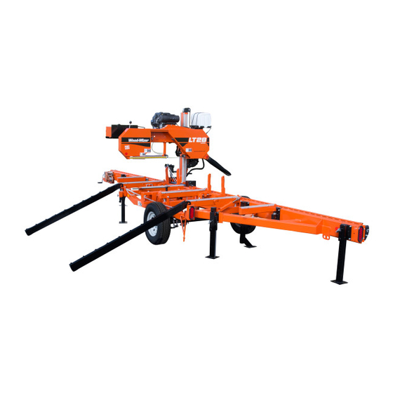
Wood-mizer LT28 Safety, Setup, Operation & Maintenance Manual
Sawmill
Hide thumbs
Also See for LT28:
- Safety, operation, maintenance & parts manual (15 pages) ,
- Safety, operation, maintenance & parts manual (19 pages)
Table of Contents
Advertisement
Quick Links
Advertisement
Table of Contents

Related Manuals for Wood-mizer LT28


Summary of Contents for Wood-mizer LT28
- Page 1 ® Wood-Mizer Sawmill Safety, Setup, Operation & Maintenance Manual LT28 rev. A1.00 - A6.01 Safety is our #1 concern! Read and understand all safety information and instructions before oper- ating, setting up or maintaining this machine. August 2005 Form #1340...
-
Page 2: Table Of Contents
Table of Contents Section-Page SECTION 1 INTRODUCTION About This Manual.................1-1 Getting Service ..................1-2 General Contact Information..........1-2 Branches & Authorized Sales Centers ........1-3 Specifications ..................1-5 Customer and Sawmill Identification.............1-7 SECTION 2 SAFETY Safety Symbols..................2-1 Safety Instructions ..................2-2 SECTION 3 SAWMILL SETUP Stationary Sawmill Setup ...............3-1 Portable Sawmill Setup ................3-3 Replacing The Blade ................3-7... - Page 3 Charging The Battery ................5-18 MAINTENANCE LOG 5-20 SECTION 6 TROUBLESHOOTING GUIDE Sawing Problems ..................6-1 Power Feed Problems ................6-3 LT28 Rev. A1.00 - A6.01 ............6-3 SECTION 7 SAWMILL ALIGNMENT Routine Alignment Procedure ..............7-1 Blade Installation..............7-1 Saw Head Tilt................7-2 Blade Guide Arm Alignment ..........7-4 Blade Guide Vertical Tilt Alignment........7-6...
-
Page 4: Introduction
The information and instructions given in this manual do not amend or extend the limited warranties for the equipment given at the time of purchase. For general information regarding Wood-Mizer and our “Forest to Final Form” products, please refer to the All Products Catalog in your support package. -
Page 5: Getting Service
Getting Service Getting Service Wood-Mizer is committed to providing you with the latest technology, best quality and strongest customer service available on the market today. We continually evaluate our customers’ needs to ensure we’re meeting current wood-processing demands. Your com- ments and suggestions are welcome. -
Page 6: Branches & Authorized Sales Centers
Wood-Mizer Canada Wood-Mizer Branches Authorized Sales Centers* Branches 2 Wood-Mizer Northeast 6 California 17 Wood-Mizer Canada East 8604 State Route 104 6980 Camp Far West Road Box 173, 2600 #1 Hwy Hannibal, NY 13074 Sheridan, CA 95681 Aylesford, NS B0P 1C0... - Page 7 Introduction Branches & Authorized Sales Centers 5 Wood-Mizer Missouri 9 Pennsylvania Authorized Sales Centers* 9664 Lawrence 2130 22638 Croghan Pike Mt. Vernon, MO 65712 Shade Gap, PA 17255 20 Ontario North Phone (417) 466-9500 Phone (814) 259-9976 2340 Dawson Road...
-
Page 8: Specifications
Introduction Specifications Specifications Model: LT28 Rev. A1.00+ Dimensions: Metric Length: 26'-4" 8.02m Width: 6'-6" 1.97m Height (Ground To Mast): 7'-2" 2.18m Height (Max Head Position): 8'5" 2.5m Bed Height (Ground To Bed): 31 1/4" 0.79m Blade Length: 158" 4.01m Weights:... - Page 9 Introduction Specifications Battery Specifications Group Type No. Performance Level Approximate Maximum Overall Dimensions Weight Cranking Reserve Length Width Height Performance Capacity 526MF 535CC 31.0 lb. 8.5 in. 6.75 in. 8.0 in. (14.06 kg) (216 mm) (171 mm) (203 mm) Introduction 2804doc030317...
-
Page 10: Customer And Sawmill Identification
Customer and Sawmill Identification Customer and Sawmill Identification Each Wood-Mizer sawmill has a model number and a 17-digit Vehicle Identification Num- ber (VIN). In addition, when you pick up your mill, you will receive a customer number. These three numbers will help expedite our service to you. Please locate them now and write them below so you have quick, easy access to them. - Page 11 Introduction Customer and Sawmill Identification The model number and V.I.N. can be found in the following locations. 250042 MODEL NUMBER AND V.I.N. LOCATIONS. Introduction 2804doc030317...
-
Page 12: Safety
Safety Safety Symbols SECTION 2 SAFETY Safety Symbols The following symbols and signal words call your attention to instructions concerning your personal safety. Be sure to observe and follow these instructions. DANGER! indicates an imminently hazardous situation which, if not avoided, will result in death or serious injury. WARNING! suggests a potentially hazardous situation which, if not avoided, could result in death or serious injury. -
Page 13: Safety Instructions
It is always the owner's responsibility to comply with all applicable federal, state and local laws, rules and regulations regarding the ownership, operation and towing of your Wood-Mizer sawmill. All Wood-Mizer mill owners are encouraged to become thoroughly familiar with these applicable laws and comply with them fully while using or towing the mill. - Page 14 Safety Safety Instructions WEAR SAFETY CLOTHING WARNING! Secure all loose clothing and jewelry before operating the sawmill. Failure to do so may result in serious injury or death. WARNING! Always wear gloves and eye protection when handling bandsaw blades. Changing blades is safest when done by one per- son! Keep all other persons away from area when coiling, carrying or changing a blade.
- Page 15 Failure to do so may result in serious injury. WARNING! Use ONLY water and Wood-Mizer Lube Additive with the water lube accessory. Never use flammable fuels or liquids such as diesel fuel. If these types of liquids are necessary to clean the blade, remove it and clean with a rag.
- Page 16 Safety Safety Instructions USE CAUTION WHEN WORKING WITH BATTERIES DANGER! Batteries expel explosive gases. Keep sparks, flames, burning cigarettes, or other ignition sources away at all times. Always wear safety goggles and a face shield when working near batteries. Failure to do so will cause serious injury. WARNING! Battery posts, terminals and related accessories con- tain lead and lead compounds, chemicals known to the State of...
- Page 17 Safety Safety Instructions CAUTIONS FOR SAWMILL SETUP WARNING! Do not set up the mill on ground with more than a 10 degree incline. If setup on an incline is necessary, put blocks under one side of the mill or dig out areas for the outrigger legs to keep mill level.
- Page 18 Safety Safety Instructions CHECK SAWMILL BEFORE OPERATION DANGER! Make sure all guards and covers are in place and secured before operating or towing the sawmill. Failure to do so may result in serious injury. Be sure the blade housing and pulley covers are in place and secure.
- Page 19 Safety Safety Instructions KEEP PERSONS AWAY DANGER! Stay clear of the area between the trailer axle and saw carriage. Failure to do so will result in serious injury. DANGER! Keep all persons out of the path of moving equipment and logs when operating sawmill or loading and turning logs. Fail- ure to do so will result in serious injury.
- Page 20 Safety Safety Instructions KEEP HANDS AWAY DANGER! Always disengage the blade and shut off the sawmill engine before changing the blade. Failure to do so will result in serious injury. DANGER! Engine components can become very hot during opera- tion. Avoid contact with any part of a hot engine. The exhaust com- ponents of your engine are especially hot during and following operation.
- Page 21 Safety Safety Instructions CAUTIONS FOR GAS OR DIESEL ENGINE OPERATION DANGER! Operate your engine/machine only in well venti- lated areas. The exhaust gases of your engine can cause nausea, delirium and potentially death unless adequate ventilation is present. DANGER! Never operate an engine with a fuel or oil leak. The leaking fuel or oil could potentially come in contact with hot surfaces and ignite into flames.
- Page 22 Safety Safety Instructions USE PROPER PROCEDURE WHEN CONDUCTING ELECTRICAL SAFETY CHECKS AND MAINTENANCE DANGER! Make sure all electrical installation, service and/or maintenance work is performed by a qualified electrician and is in accordance with applicable electrical codes. DANGER! ARC FLASH AND SHOCK HAZARD! Hazardous volt- age inside the electric sawmill disconnect box, starter box, and at the motor can cause shock, burns, or death.
- Page 23 Safety Safety Instructions DANGER! Lockout procedures must be used during: Changing or adjusting blades Unjamming operations Cleaning Mechanical repair Electrical maintenance Retrieval of tools/parts from work area Activities where guards or electrical panel guard is open or removed Maintenance hazards include: Blade contact Pinch points Kickbacks...
- Page 24 Safety Safety Instructions SAWMILL LOCKOUT PROCEDURE Lockout procedures must be followed (see ANSI Standard Z244.1-1982 and OSHA regu- lation 1910.147). Purpose: This procedure establishes the minimum requirements for lockout of energy sources that could cause injury. Responsibility: The responsibility for seeing that this procedure is followed is binding upon all workers. All workers shall be instructed in the safety significance of the lockout procedure.
- Page 25 Owner’s Responsibility The procedures listed in this manual may not include all ANSI, OSHA, or locally required safety procedures. It is the owner/operator’s responsibility and not Wood-Mizer Products to ensure all operators are properly trained and informed of all safety protocols.
- Page 26 Safety Safety Instructions KEEP SAFETY LABELS IN GOOD CONDITION IMPORTANT! Always be sure that all safety decals are clean and readable. Replace all damaged safety decals to prevent personal injury or damage to the equipment. Contact your local distributor, or call your Customer Service Representative to order more decals.
- Page 27 Safety Safety Instructions UP/DOWN SYSTEM SAFETY WARNING! Always secure the saw head with a 5/16" chain with at least 1900 lbs. working load capacity before adjusting the up/down chain. The saw head may fall, causing severe injury or death. WARNING! Always secure the saw head with a 5/16"...
- Page 28 Safety Safety Instructions GENERAL TRAILER SAFETY DANGER! Make sure your hitch has adequate safety chain hook- ups. Do not use eyebolts for safety chain hook-up. Safety chains should be hooked to bumper of vehicle so that each chain would pull the trailer equally in the event the hitch became disengaged. Failure to do so may result in serious personal injury and/or severe machine damage.
-
Page 29: Sawmill Setup
Sawmill Setup Stationary Sawmill Setup SECTION 3 SAWMILL SETUP Stationary Sawmill Setup Prepare a firm, level area where the sawmill can be anchored. There should be enough room around the sawmill for operators, sawdust removal, log loading and board removal. A cement pad with 5/8”... - Page 30 Sawmill Setup Stationary Sawmill Setup 2804doc030317 Sawmill Setup...
-
Page 31: Portable Sawmill Setup
Sawmill Setup Portable Sawmill Setup Portable Sawmill Setup WARNING! Do not set up the mill on ground with more than a 10 degree incline. If setup on an incline is necessary, put blocks under one side of the mill or dig out areas for outrig- ger legs to keep mill level. - Page 32 Sawmill Setup Portable Sawmill Setup 1. Unhitch the mill from the vehicle. 2. Lower and set the front three outriggers. To lower, use the provided jack handle to lift the weight from the locking pin. If necessary, rotate the locking pin counterclockwise so that the inner roll pin is free from the outrigger channel notch, then pull the locking pin out to release the outrigger.
- Page 33 Sawmill Setup Portable Sawmill Setup See Figure 3-3. For Fine Adjust Outriggers (FAOs), lower the outrigger as close to the ground as possible, then secure in place with the locking pin. Adjust the outrigger base so that it contacts the ground. To adjust, use the provided wrench to turn the height adjust- ment nut.
- Page 34 Sawmill Setup Portable Sawmill Setup mill frame by jacking one outrigger higher than the others. For FAO(s), fine tune the outrigger base height as necessary. Move the cutting head to the opposite end of the mill from the outrigger. Raise the entire outrigger (to remove the sawmill weight from it) and adjust the outrigger base as necessary.
-
Page 35: Replacing The Blade
Sawmill Setup Replacing The Blade Replacing The Blade DANGER! Always disengage the blade and shut off the sawmill engine before changing the blade. Failure to do so will result in serious injury. WARNING! Always wear gloves and eye protection when handling bandsaw blades. -
Page 36: Tensioning The Blade
Sawmill Setup Tensioning The Blade Tensioning The Blade The blade tensioner is factory-set so proper blade tension is achieved when the rubber spring is compressed 3/16” (4.8 mm). An indicator bolt is provided to indicate when the rubber spring has been compressed properly. To tension the blade, turn the blade tension handle up until it locks in place. - Page 37 Sawmill Setup Tensioning The Blade See Figure 3-6. Rev. A1.00 - A1.02: Use the roll pin at the end of the assembly to turn the shaft. Blade Tension Handle Use roll pin to adjust shaft Rubber Spring Blade Tension Indicator Bolt Back of 280014B washer aligned...
-
Page 38: Tracking The Blade
Sawmill Setup Tracking The Blade Tracking The Blade 1. Make sure the blade housing covers are closed and all persons are clear of the open side of the saw head. 2. Start the engine. 3. Engage the blade, rotating the blade until the blade positions itself on the wheels. WARNING! Do not spin the blade wheels by hand. - Page 39 Sawmill Setup Tracking The Blade See Figure 3-8. To adjust where the blade travels on the blade wheels, use the cant con- trol. Cant Control 280013 FIG. 3-8 If the blade is too far out, back the blade onto the wheel by turning the cant control coun- terclockwise.
- Page 40 Sawmill Setup Tracking The Blade 3-12 2804doc030317 Sawmill Setup...
-
Page 41: Starting The Engine
Sawmill Setup Starting The Engine Starting The Engine See the appropriate manual supplied with your specific engine/motor configuration for starting and operating instructions. DANGER! Make sure all guards and covers are in place and secured before operating or towing the sawmill. Failure to do so may result in serious injury. -
Page 42: Sawmill Operation
Sawmill Operation Loading, Turning And Clamping Logs SECTION 4 SAWMILL OPERATION Loading, Turning And Clamping Logs To Load Logs 1. Move the saw carriage to the front end of the frame. CAUTION! Before loading a log, be sure the cutting head is moved far enough forward so the log does not hit it. - Page 43 Sawmill Operation Loading, Turning And Clamping Logs 1. Use cant hooks or the optional log turner to rotate the log on the sawmill bed. See Log Turner Manual. 2. Spin the log against the side supports until it is turned the way you want it for the first cut. To Clamp Logs 1.
-
Page 44: Up/Down Operation
Sawmill Operation Up/Down Operation Up/Down Operation 1. Install a blade, if needed, and check for correct blade tension. (See Section 3.3). 2. Set the cutting head to the desired height. (The blade height scale shows the height of the blade above the bed rails.) See Figure 4-2. -
Page 45: Blade Guide Arm Operation
Sawmill Operation Blade Guide Arm Operation Blade Guide Arm Operation 1. Look down the length of the log to see its maximum width. The outer blade guide should be adjusted to clear the widest section of the log by less than 1" (25.4 mm). See Figure 4-3. -
Page 46: Clutch Operation
Sawmill Operation Clutch Operation Clutch Operation 1. Clear any loose objects from the area of the blade, motor, and drive belt. 2. Make sure the clamp and side supports are adjusted below the level of your first few cuts. 3. Start the engine as instructed in the option manual. DANGER! Keep all persons out of the path of moving equipment and logs when operating sawmill or loading and... -
Page 47: Feed Operation
Sawmill Operation Feed Operation Feed Operation STANDARD MANUAL FEED: 1. Use the feed crank handle to move the saw carriage forward. See Figure 4-5. Squeeze the engagement lever and rotate the feed crank clockwise. Turn crank clockwise for forward feed; counterclockwise to return carriage Engagement Lever... - Page 48 Sawmill Operation Feed Operation Carriage Forward Forward Feed Rate Carriage Reverse 280032 FIG. 4-6 Carriage Feed Rate The carriage feed rate switch controls the speed at which the carriage travels forward. Turn the switch clockwise to increase speed. Turn it counterclockwise to reduce speed. Carriage Forward and Reverse The carriage forward/reverse switch controls the direction in which the carriage travels.
- Page 49 Sawmill Operation Feed Operation desired. Maximum feed rate varies with width and hardness of the wood. Over-feeding results in engine and blade wear, and also produces a wavy cut. 2. Stop the carriage at the end of the cut. The blade will continue to spin as long as the blade motor is on.
-
Page 50: Cutting The Log
Cutting The Log Cutting The Log The following steps guide you through normal operation of the Wood-Mizer sawmill. 1. Once the log is placed where you want it and clamped firmly, move the saw head to posi- tion the blade close to the end of the log. - Page 51 Sawmill Operation Cutting The Log 9. Lower the toe boards, if they were used. Remove the clamp and turn the log 90 or 180 degrees. Make sure the flat on the log is placed flat against side supports if turned 90 degrees.
-
Page 52: Edging
Sawmill Operation Edging Edging The following steps guide you through edging boards on the Wood-Mizer sawmill. 1. Raise the side supports to 1/2 the height of the flitches, or the boards that need to be edged. 2. Stack the flitches on edge against the side supports. -
Page 53: Blade Height Scale
Sawmill Operation Blade Height Scale Blade Height Scale See Figure 4-7. The blade height scale is attached to the carriage head frame. It includes: blade height indicator an inch scale a magnetic quarter scale Blade Height Inch Scale Indicator 280004 FIG. - Page 54 Sawmill Operation Blade Height Scale The Quarter Scale See Table 4-1. The magnetic quarter scale has four sets of marks. Each set represents a specific lumber thickness. Saw kerf and shrinkage allowance are included, but actual board thickness will vary slightly depending on blade thickness and tooth set. Standard Quarter Scale Scale Actual Board Thickness...
-
Page 55: Water Lube Operation
15 seconds. This will clean the blade of sap buildup. Wipe the blade dry with a rag before storing or sharpening. For further lubrication benefits, add one 12oz. bottle of Wood-Mizer Lube Additive to 5 gallons of water. Wood-Mizer Lube Additive enables some previously impossible timbers to be cut by significantly reducing resin buildup on the blade. - Page 56 Sawmill Operation Water Lube Operation If you are sawing in freezing temperatures, remove the water lube bottle from the sawmill when done sawing and store it in a warm place. Blow any remaining water from the water lube hose. 4-28 2804doc030317 Sawmill Operation...
-
Page 57: 4.10 Preparing The Sawmill For Towing
Preparing The Sawmill For Towing 4.10 Preparing The Sawmill For Towing The Wood-Mizer trailer package makes transporting your sawmill easy and convenient. To get your sawmill ready for towing, follow these instructions. 1. Move the saw carriage to the front end of the sawmill. Raise the rear outriggers. - Page 58 Sawmill Operation Preparing The Sawmill For Towing 4. Position the hole in the saw head over the travel rest pin. 5. Lower the saw head until it is seated firmly on the rest pin. See Figure 4-10. Saw Head Rest Pin FIG.
- Page 59 Sawmill Operation Preparing The Sawmill For Towing Loosen jam nut and turn bolt to raise or lower stop bolt 280015 FIG. 4-11 8. Engage the clutch lever. This keeps the drive belt tight and the motor from bouncing while traveling. Be sure to disengage the clutch lever after reaching the destination to avoid deformation of the drive belt.
- Page 60 Sawmill Operation Preparing The Sawmill For Towing and secure. Use the safety retainer pin and cable to fasten blade housing covers. 11. Remove all loose objects from the bed of the mill. Store the outrigger jack handle in the bracket provided on the rear/loading-side outrigger guide. Reel in the winch cable and remove the winch handle.
-
Page 61: Maintenance
Wear Life SECTION 5 MAINTENANCE This section lists the maintenance procedures that need to be performed. See the Maintenance Log located after this section for a complete list of maintenance procedures and intervals. Keep track of machine maintenance by filling in the machine hours and the date you perform each procedure. -
Page 62: Blade Guides
Maintenance Blade Guides Blade Guides WARNING! Before performing service near moving parts such as blades, pulleys, motors, belts and chains, first turn the key switch to the OFF (#0) position and remove the key. If the key is turned on and moving parts activated, serious injury may result. -
Page 63: Sawdust Removal
Maintenance Sawdust Removal Sawdust Removal WARNING! Before performing service near moving parts such as blades, pulleys, motors, belts and chains, first turn the key switch to the OFF (#0) position and remove the key. If the key is turned on and moving parts activated, serious injury may result. -
Page 64: Carriage Track, Wiper & Scrapers
Maintenance Carriage Track, Wiper & Scrapers Carriage Track, Wiper & Scrapers WARNING! Before performing service near moving parts such as blades, pulleys, motors, belts and chains, first turn the key switch to the OFF (#0) position and remove the key. If the key is turned on and moving parts activated, serious injury may result. - Page 65 Maintenance Carriage Track, Wiper & Scrapers 3. Check the track scrapers as needed. Make sure the scrapers fit firmly against the rail. If a track scraper needs to be adjusted, loosen the screw, push the scraper downward until it fits firmly against the rail, and retighten the screw. Carriage track Remove track wiper, clean...
-
Page 66: Vertical Mast Rails
Maintenance Vertical Mast Rails Vertical Mast Rails WARNING! Before performing service near moving parts such as blades, pulleys, motors, belts and chains, first turn the key switch to the OFF (#0) position and remove the key. If the key is turned on and moving parts activated, serious injury may result. -
Page 67: Miscellaneous
Maintenance Miscellaneous Miscellaneous WARNING! Before performing service near moving parts such as blades, pulleys, motors, belts and chains, first turn the key switch to the OFF (#0) position and remove the key. If the key is turned on and moving parts activated, serious injury may result. -
Page 68: Blade Wheel Belts
Maintenance Blade Wheel Belts Blade Wheel Belts WARNING! Before performing service near moving parts such as blades, pulleys, motors, belts and chains, first turn the key switch to the OFF (#0) position and remove the key. If the key is turned on and moving parts activated, serious injury may result. -
Page 69: Drive Belt Adjustment
See Table 5-2. See the table below for drive belt tension specifications for your model sawmill. Wood-Mizer offers a belt tension gauge (Part No. 016309) that will let you accu- rately measure the belt tension. - Page 70 Maintenance Drive Belt Adjustment See Figure 5-2. Throttle Linkage Adjustment Turn jam nut clockwise to loosen drive belt 7/16" (11 mm) Hex Nut 280006B 2. GAS OPTION ONLY: After tensioning the drive belt, check the throttle linkage and adjust if necessary. With the clutch handle engaged, the throttle linkage should move the throttle lever to full speed.
-
Page 71: Up/Down System
Maintenance Up/Down System Up/Down System WARNING! Before performing service near moving parts such as blades, pulleys, motors, belts and chains, first turn the key switch to the OFF (#0) position and remove the key. If the key is turned on and moving parts activated, serious injury may result. - Page 72 Maintenance Up/Down System The up/down system is equipped with a gas spring assist mechanism to provide improved speed and performance. The saw head must be secured and tension released from the assist assembly before performing any maintenance to assist components. WARNING! Always secure the saw head with a 5/16"...
- Page 73 Maintenance Up/Down System is recommended two people lift the assembly from the mast. A hoist or some other mechanical method may also be used. 5. Once the assist assembly is removed, components may easily be disassembled and ser- viced as needed. Do not disassemble the gas spring cylinders. WARNING! The gas spring cylinders are pressurized.
-
Page 74: 5.10 Feed Rope
Maintenance Feed Rope 5.10 Feed Rope WARNING! Before performing service near moving parts such as blades, pulleys, motors, belts and chains, first turn the key switch to the OFF (#0) position and remove the key. If the key is turned on and moving parts activated, serious injury may result. - Page 75 Maintenance Feed Rope 2. Loop the rope clockwise around the lower double groove roller and route to the feed crank handle. See Figure 5-7. Loop the feed rope around the lower roller groove closer to the bed frame tube. 280040-3 FIG.
- Page 76 Maintenance Feed Rope 3. Loop the rope counterclockwise around the feed crank pulley and route back down to the lower double groove roller. See Figure 5-8. Loop the feed rope around the feed crank pulley three times. TOP VIEW Lower Double Groove Roller 280040-5 Feed Pulley...
- Page 77 Maintenance Feed Rope 4. Route the rope clockwise around the outer groove of the lower roller. See Figure 5-9. 280040-4 FIG. 5-9 5. Route the rope to the rear end of the mill. Slip the rope through one hole in the rope lock plate and the eye bolt.
-
Page 78: 5.11 Charging The Battery
Maintenance Charging The Battery 5.11 Charging The Battery DANGER! Batteries expel explosive gases. Keep sparks, flames, burning cigarettes, or other ignition sources away at all times. Always wear safety goggles and a face shield when working near batteries. Failure to do so will cause serious injury. - Page 79 Maintenance Charging The Battery CAUTION! Be sure the battery is fully charged before transporting the sawmill. If the battery is not fully charged, excessive vibration could reduce the overall service life of the battery. 1. Turn the key to the OFF (#0) position and remove the key. 2.
-
Page 80: Maintenance Log
MAINTENANCE LOG (Check Engine And Option Manuals For Additional Maintenance Procedures) Check Blade Guide Roller Wear See Section 5.2 Daily - Every Blade Change Remove Excess Sawdust From Blade Wheel Hous- See Section 5.3 Daily - Every Blade Change DAILY MAINTENANCE PROCEDURES ings And Sawdust Chute Inspect Fingers Inside Sawdust Chute See Section 5.3... - Page 81 MAINTENANCE LOG (Check Engine And Option Manuals For Additional Maintenance Procedures) TOTAL HOURS OF OPERATION MANUAL FILL IN THE DATE AND THE MACHINE HOURS AS YOU PERFORM EACH PROCEDURE. PROCEDURE REFERENCE A SHADED BOX INDICATES MAINTENANCE IS NOT NEEDED AT THIS TIME. 550 HRS 600 HRS 650 HRS...
- Page 82 MAINTENANCE LOG (Check Engine And Option Manuals For Additional Maintenance Procedures) TOTAL HOURS OF OPERATION MANUAL FILL IN THE DATE AND THE MACHINE HOURS AS YOU PERFORM EACH PROCEDURE. PROCEDURE REFERENCE A SHADED BOX INDICATES MAINTENANCE IS NOT NEEDED AT THIS TIME. 1050 HRS 1100 HRS 1150 HRS...
- Page 83 MAINTENANCE LOG (Check Engine And Option Manuals For Additional Maintenance Procedures) TOTAL HOURS OF OPERATION MANUAL FILL IN THE DATE AND THE MACHINE HOURS AS YOU PERFORM EACH PROCEDURE. PROCEDURE REFERENCE A SHADED BOX INDICATES MAINTENANCE IS NOT NEEDED AT THIS TIME. 1550 HRS 1600 HRS 1650 HRS...
- Page 84 MAINTENANCE LOG (Check Engine And Option Manuals For Additional Maintenance Procedures) TOTAL HOURS OF OPERATION MANUAL FILL IN THE DATE AND THE MACHINE HOURS AS YOU PERFORM EACH PROCEDURE. PROCEDURE REFERENCE A SHADED BOX INDICATES MAINTENANCE IS NOT NEEDED AT THIS TIME. 2050 HRS 2100 HRS 2150 HRS...
- Page 85 MAINTENANCE LOG (Check Engine And Option Manuals For Additional Maintenance Procedures) TOTAL HOURS OF OPERATION MANUAL FILL IN THE DATE AND THE MACHINE HOURS AS YOU PERFORM EACH PROCEDURE. PROCEDURE REFERENCE A SHADED BOX INDICATES MAINTENANCE IS NOT NEEDED AT THIS TIME. 2550 HRS 2600 HRS 2650 HRS...
-
Page 86: Troubleshooting Guide
Troubleshooting Guide Sawing Problems SECTION 6 TROUBLESHOOTING GUIDE Sawing Problems WARNING! Before performing service near moving parts such as blades, pulleys, motors, belts and chains, first turn the key switch to the OFF (#0) position and remove the key. If the key is turned on and moving parts activated, serious injury may result. - Page 87 Troubleshooting Guide Sawing Problems PROBLEM CAUSE SOLUTION Boards Thick Or Thin On Stress in log which causes log After log has been squared, take Ends Or Middle Of Board. to not lay flat on the bed. equal cuts off opposing sides. Take a board off the top.
-
Page 88: Power Feed Problems
Troubleshooting Guide Power Feed Problems Power Feed Problems LT28 Rev. A1.00 - A6.01 Follow the instructions below to solve the possible power feed problems. See Figure 6-1. FIG. 6-1 Testing Components: 1. Free Wheeling Diode Test: Remove the blue wire from the motor terminal of the Mosfet. - Page 89 Troubleshooting Guide LT28 Rev. A1.00 - A6.01 2. Mosfet Test - disconnect all wires: Set meter to Ohms. Connect the red lead to “S” or “GND” terminal. Connect the black lead to “G” or unmarked small terminal. The meter should read no less than approximately 1k Ohms.
-
Page 90: Sawmill Alignment
Routine Alignment Procedure SECTION 7 SAWMILL ALIGNMENT The Wood-Mizer sawmill is factory aligned. Two alignment procedures are available to realign the sawmill if necessary. The Routine Alignment instructions should be performed as necessary to solve sawing problems not related to blade performance. The Complete Alignment procedure should be performed approximately every 1500 hours of operation (sooner if you regularly transport the sawmill over rough terrain). -
Page 91: Saw Head Tilt
Sawmill Alignment Routine Alignment Procedure Saw Head Tilt As the blade enters a wide log or cant, the outside of the saw head will drop down slightly. To compensate for the drop, the saw head is adjusted 1/16" (1.5 mm) higher at the out- side. - Page 92 Sawmill Alignment Routine Alignment Procedure See Figure 7-2. To adjust the saw head tilt, use the horizontal adjustment nuts. To raise the outside of the saw head, tighten the two adjustment nuts. Recheck the measurement from the blade to the bed rails and adjust the horizontal adjustment nuts until the outside of the saw head is 1/16"...
-
Page 93: Blade Guide Arm Alignment
Sawmill Alignment Routine Alignment Procedure Blade Guide Arm Alignment The blade guide arm moves the outer blade guide in and out. If the arm becomes loose, the blade guide will not deflect the blade properly, causing inaccurate cuts. A loose blade guide arm can also cause blade vibration. - Page 94 Sawmill Alignment Routine Alignment Procedure See Figure 7-4. With the blade guide arm still all the way in toward the other blade guide, tighten all the side screws until they touch the arm. Back the screws off 1/4 turn and tighten the jam nuts.
-
Page 95: Blade Guide Vertical Tilt Alignment
Sawmill Alignment Routine Alignment Procedure Blade Guide Vertical Tilt Alignment The blade guides should be adjusted properly in the vertical plane. If the blade guides are tilted vertically, the blade will try to travel in the tilted direction. A Blade Guide Alignment Tool (BGAT) is provided to help you measure the vertical tilt of the blade. - Page 96 Sawmill Alignment Routine Alignment Procedure See Figure 7-6. Loosen the jam nuts on the top and bottom vertical tilt adjustment screws. To tilt the roller up, loosen the bottom screw and tighten top screw. To tilt the roller down, loosen the top screw and tighten the bottom screw. Tighten the jam nuts and recheck the tilt of the blade.
-
Page 97: Blade Guide Horizontal Tilt Adjustment
Sawmill Alignment Routine Alignment Procedure Blade Guide Horizontal Tilt Adjustment If the blade guides are tilted in the wrong direction horizontally, the back of the blade may contact the flange as the roller is spinning down, causing it to push the blade away from the guide roller. - Page 98 Sawmill Alignment Routine Alignment Procedure See Figure 7-8. Loosen the jam nuts on the horizontal tilt adjustment screws. To tilt the roller left, loosen the right screw and tighten left screw. To tilt the roller right, loosen the left screw and tighten the right screw. Tighten the jam nuts and recheck the tilt of the blade.
-
Page 99: Blade Guide Flange Spacing
Sawmill Alignment Routine Alignment Procedure Blade Guide Flange Spacing Each blade guide must be adjusted so the roller flange is the correct distance from the back edge of the blade. If the flange is too close to or too far from the blade, the sawmill will not cut accurately. -
Page 100: Side Support Alignment
Sawmill Alignment Routine Alignment Procedure Side Support Alignment Logs and boards are clamped against the side supports when sawing. The sides supports must be square to the bed to ensure square lumber. 1. Swing a side support down and measure between the face of the support and the main bed tube. - Page 101 Sawmill Alignment Routine Alignment Procedure See Figure 7-11. Loosen the side support mounting bolt. Use a 3/8" ratchet to rotate the pin until the side support is square to the bed. Alignment Tubes (2) Place square against side support Loosen mounting bolt SM0272-1 Use 3/8”...
-
Page 102: Blade Height Scale Adjustment
Sawmill Alignment Routine Alignment Procedure Blade Height Scale Adjustment After the entire sawmill has been aligned and all adjustments made, check that the blade height scale indicates the true distance from the blade to the bed rails. 1. Move the saw carriage so the blade is positioned directly above one of the bed rails. Mea- sure from the bottom edge on a down-set tooth of the blade to the top of the bed rail, near the inner blade guide assembly. -
Page 103: Complete Alignment Procedure
If your sawmill has a trailer axle and adjustable outriggers, adjust the outriggers as fol- lows: LT28: Adjust the two outriggers on the main frame tube down just enough to lift weight from the trailer tire. All Portable Sawmills: Adjust the two outer outriggers down just so they touch the ground but do not bear weight. -
Page 104: Blade Installation
Sawmill Alignment Complete Alignment Procedure Blade Installation 1. Remove the blade and replace the blade wheel belts. New blade wheel belts are required to perform the complete alignment procedure. 2. Blow sawdust off of the blade guide assemblies. Remove sawdust from the blade hous- ings. -
Page 105: Blade Wheel Alignment
Sawmill Alignment Complete Alignment Procedure Blade Wheel Alignment The blade wheels should be adjusted so they are level in the vertical and horizontal planes. If the blade wheels are tilted up or down, the blade will want to travel in the tilted direction. - Page 106 Sawmill Alignment Complete Alignment Procedure 150075-1B Blade Guide Alignment Tool Adjust vertical adjustment screws down to tilt drive-side blade wheel up; Adjust screws up to tilt wheel down FIG. 7-14 5. Recheck the vertical tilt of the drive-side blade wheel with the blade guide alignment tool. Readjust the blade wheel as necessary until the front and rear of the tool are the same distance from the bed rail (within 1/16"...
- Page 107 Sawmill Alignment Complete Alignment Procedure Adjust vertical adjustment screws up to tilt idle-side blade wheel down; Adjust screws down to tilt wheel up 280012 FIG. 7-15 8. Recheck the vertical tilt of the idle-side blade wheel with the blade guide alignment tool. Readjust the blade wheel as necessary until the front and rear of the tool are the same distance from the bed rail (within 1/16"...
- Page 108 Sawmill Alignment Complete Alignment Procedure 9. Check the position of the blade on the idle-side blade wheel. See Figure 7-16. The horizontal tilt of the blade wheel should be adjusted so that the gul- let of an 1-1/4" blade is 1/8" (3 mm) out from the front edge of the wheel (±1/32 [0.75 mm]).
- Page 109 Sawmill Alignment Complete Alignment Procedure wheel if necessary. See Figure 7-18. Use the horizontal adjustment screws to adjust the drive-side blade wheel. To move the blade back on the wheel, loosen the right adjustment screw one quar- ter turn. Loosen the jam nut on the left adjustment screw and tighten the screw. Tighten the left and right jam nuts.
- Page 110 Sawmill Alignment Complete Alignment Procedure See Figure 7-19. To adjust the saw head tilt, use the horizontal adjustment nuts. To raise the outside of the saw head, tighten the two adjustment nuts. Recheck the measurement from the blade to the bed rails and adjust the horizontal adjustment nuts until the outside of the saw head is 1/16"...
-
Page 111: Bed Rail Adjustment
Sawmill Alignment Complete Alignment Procedure Bed Rail Adjustment 1. Install the log clamp at its lowest setting in a hole where the clamp is positioned 10" from the clamp stop (fourth hole from stop). Move the saw head until the blade is centered over the clamp. - Page 112 Sawmill Alignment Complete Alignment Procedure adjustment bolt to adjust the height of the outer end of the pivot rail. SM0134B 15" (375mm) to blade 15" (375mm) to blade Inner Height Adjustment Outer Height Adjustment Bolt FIG. 7-21 6. Move the saw head so the blade is positioned over the center of the front main bed rail. 7.
- Page 113 Sawmill Alignment Complete Alignment Procedure See Figure 7-22. Loosen the bed rail clamping bolts and turn the adjustment bolts to move the bed rails to the blade if necessary. Retighten the clamping bolts and adjustment bolt jam nuts. Blade 15“ (375.0 mm) 15“...
-
Page 114: Blade Guide Installation
Complete Alignment Procedure Blade Guide Installation Each Wood-Mizer sawmill has two blade guide assemblies that help the blade maintain a straight cut. The two blade guide assemblies are positioned on the saw head to guide the blade on each side of the material being cut. - Page 115 Sawmill Alignment Complete Alignment Procedure See Figure 7-23. Tighten the two previously-loosened tilt adjustment screws to secure the blade guide assembly. Loosen the top vertical adjustment jam nut and tighten the bottom vertical adjustment jam nut to adjust the blade guide roller up so it does not touch the blade. Top Vertical Adjustment Jam Nut Tilt Adjustment...
-
Page 116: Blade Guide Arm Alignment
Sawmill Alignment Complete Alignment Procedure Blade Guide Arm Alignment The blade guide arm moves the outer blade guide in and out. If the arm becomes loose, the blade guide will not deflect the blade properly, causing inaccurate cuts. A loose blade guide arm can also cause blade vibration. - Page 117 Sawmill Alignment Complete Alignment Procedure See Figure 7-25. With the blade guide arm still all the way in toward the other blade guide, tighten all the side screws until they touch the arm. Back the screws off 1/4 turn and tighten the jam nuts. Blade Guide Arm Parallel to Blade Adjust side screws to 150036B...
-
Page 118: Blade Guide Deflection
Sawmill Alignment Complete Alignment Procedure Blade Guide Deflection Perform the following steps to achieve proper blade deflection with the blade guides. 1. Raise the saw head until the blade is 15" (375 mm) above a bed rail. Measure the actual distance with a tape from the top of the rail to the bottom of the blade. -
Page 119: Blade Guide Vertical Tilt Alignment
Sawmill Alignment Complete Alignment Procedure Blade Guide Vertical Tilt Alignment The blade guides should be adjusted properly in the vertical plane. If the blade guides are tilted vertically, the blade will try to travel in the tilted direction. A Blade Guide Alignment Tool (BGAT) is provided to help you measure the vertical tilt of the blade. - Page 120 Sawmill Alignment Complete Alignment Procedure See Figure 7-28. Loosen the jam nuts on the top and bottom vertical tilt adjustment screws. To tilt the roller up, loosen the bottom screw and tighten top screw. To tilt the roller down, loosen the top screw and tighten the bottom screw. Tighten the jam nuts and recheck the tilt of the blade.
-
Page 121: Blade Guide Horizontal Tilt Adjustment
Sawmill Alignment Complete Alignment Procedure Blade Guide Horizontal Tilt Adjustment If the blade guides are tilted in the wrong direction horizontally, the back of the blade may contact the flange as the roller is spinning down, causing it to push the blade away from the guide roller. - Page 122 Sawmill Alignment Complete Alignment Procedure See Figure 7-30. Loosen the jam nuts on the horizontal tilt adjustment screws. To tilt the roller left, loosen the right screw and tighten left screw. To tilt the roller right, loosen the left screw and tighten the right screw. Tighten the jam nuts and recheck the tilt of the blade.
-
Page 123: Blade Guide Flange Spacing
Sawmill Alignment Complete Alignment Procedure Blade Guide Flange Spacing Each blade guide must be adjusted so the roller flange is the correct distance from the back edge of the blade. If the flange is too close to or too far from the blade, the sawmill will not cut accurately. -
Page 124: Side Support Alignment
Sawmill Alignment Complete Alignment Procedure Side Support Alignment Logs and boards are clamped against the side supports when sawing. The sides supports must be square to the bed to ensure square lumber. 1. Swing a side support down and measure between the face of the support and the main bed tube. - Page 125 Sawmill Alignment Complete Alignment Procedure See Figure 7-33. Loosen the side support mounting bolt. Use a 3/8" ratchet to rotate the pin until the side support is square to the bed. Alignment Tubes (2) Place square against side support Loosen mounting bolt SM0272-1 Use 3/8”...
-
Page 126: Saw Head Tilt
Sawmill Alignment Complete Alignment Procedure Saw Head Tilt As the blade enters a wide log or cant, the outside of the saw head will drop down slightly. To compensate for the drop, the saw head is adjusted 1/16" (1.5 mm) higher at the out- side. - Page 127 Sawmill Alignment Complete Alignment Procedure See Figure 7-35. To adjust the saw head tilt, use the horizontal adjustment nuts. To raise the outside of the saw head, tighten the two adjustment nuts. Recheck the measurement from the blade to the bed rails and adjust the horizontal adjustment nuts until the outside of the saw head is 1/16"...
-
Page 128: Blade Height Scale Adjustment
Sawmill Alignment Complete Alignment Procedure Blade Height Scale Adjustment After the entire sawmill has been aligned and all adjustments made, check that the blade height scale indicates the true distance from the blade to the bed rails. 1. Move the saw carriage so the blade is positioned directly above one of the bed rails. Mea- sure from the bottom edge on a down-set tooth of the blade to the top of the bed rail, near the inner blade guide assembly. - Page 129 alignment main bed rails 22 blade breakage, troubleshooting 1 installation 7 tensioning 8 tracking 10 blade guide arm operation 17 chain maintenance 7 up/down tension 11 clutch/brake lever operation 18 leveling logs 15 loading logs 14 maintenance blade guide 2 blade wheel belts 8 carriage track/wipers 4 drive belt 9...
- Page 130 blade height operation 25 inch height 25 quarter inch 26 service information branch locations 3 customer & sawmill ID 7 general contact info 2 setup portable sawmill 3 stationary sawmill 1 tensioner maintenance 7 troubleshooting 1 sawing problems 1 turning logs 14 up/down operation 16 water lube...
Need help?
Do you have a question about the LT28 and is the answer not in the manual?
Questions and answers