Table of Contents
Advertisement
Advertisement
Table of Contents

Subscribe to Our Youtube Channel
Related Manuals for Wood-mizer LX50 EH7S


Summary of Contents for Wood-mizer LX50 EH7S
- Page 3 Wood-Mizer ® Safety, Setup, Operation & Maintenance Manual LX50 EH7S rev. A1.00 LX50 G14S rev. A1.00 Safety is our #1 concern! Read and understand all safety information and instructions before operating, setting up or maintaining this machine. Form #850 This is the original language...
-
Page 4: Table Of Contents
Table of Contents Section-page General Contact Information Branches & Authorized Sales CentersWood-Mizer Locations (North and South America) SECTION 1 SAFETY INSTRUCTIONS Safety Symbols..................1-1 Blade Handling..................1-2 Sawmill Setup..................1-2 Sawmill Operation..................1-2 Refueling ....................1-4 Gas Engine Operation................1-4 Sawmill Maintenance ................1-5 Safety Instructions ..................1-6 Observe Safety Instructions Wear Safety Clothing Keep Sawmill and Area Around Sawmill Clean... - Page 5 Table of Contents Section-page 2.12 Clutch Lever Installation (Gas Sawmills) ..........2-32 SECTION 3 SAWMILL OPERATION Safety Instructions ..................3-1 Sawmill Setup..................3-1 Replacing the Blade................3-3 Tensioning the Blade................3-4 Tracking the Blade .................3-5 Horizontal Adjustment of Idle-Side Blade Wheel........3-6 Motor Drive Pulley Alignment..............3-7 Horizontal Adjustment of Drive-Side Blade Wheel.......3-7 Vertical Adjustment of Drive-Side Blade Wheel........3-8 3.10...
- Page 6 Sawmill and Customer Identification Each LX50 sawmill has an identification number including a Revision level. See the chart below for description of the Vehicle Identification Number (VIN). LX50 Version Main Motor Power Bed Length Basic Model and Supply Voltage LX50 Bed Length Engine Power Basic Model...
- Page 7 When you pick up your sawmill, you will receive a customer number. Both the sawmill identification number and your customer number expedite our service to you. Please write these numbers below so you have quick, easy access to them. Customer No. Model No.
- Page 8 -iii G24doc032021...
-
Page 9: General Contact Information
Getting Service Wood-Mizer is committed to providing you with the latest technology, best quality and strongest customer service available on the market today. We continually evaluate our customers’ needs to ensure we’re meeting current wood-processing demands. Your comments and suggestions are welcome. -
Page 10: Branches & Authorized Sales Centerswood-Mizer Locations (North And South America)
Branches & Authorized Sales CentersWood-Mizer Locations (North and South America) EUROPE UNITED STATES European Headquarters World Headquarters Wood-Mizer Industries Sp. z o.o. Wood-Mizer LLC Nagórna 114, 62-600 Koło, Poland 8180 West 10th Street Tel.: +48-63-26-26-000 Indianapolis,Indiana 46214-2400, Fax: +48-63-27-22-327 www.woodmizer.eu Tel.: +1-317-271-1542... - Page 11 CROATIA Krešimir Pregernik ITALY Pasquale Felice SERBIA Dragan Markov Pregimex d.o.o. Wood-Mizer Italia Srl Wood-Mizer Balkan d.o.o. S. Batušiæa 31, 10090 Zagreb Cda. Capoiaccio SN Svetosavska GA 3/3; P. Fah 25 Tel.:/Fax: +3851-38-94-668 86012 Cercemaggiore 23 300 Kikinda Krešimir Pregernik Campobasso Tel.:/Fax: +381-230-25-754...
- Page 12 Robert Moxham DENMARK Kevin Christiansen TRANSILVANIEI Nr. 5 Regional Direction - Asia Kevin Christiansen's Sibiu, Cisnadie 555300 Wood-Mizer Asia Manufacturing Co., Ltd. savværker PMV Tel.:/Fax: : +40-369-405-433 No.2, Gongyequ 40th Rd. Xitun District, Arnborgvej 40, 7330 Brande- Fasterholt GSM: +40-745-707-323 Taichung City, 40768, Taiwan, R.O.C.
- Page 13 Branches & Authorized Sales CentersWood-Mizer Locations (North and South America) Serving Brazil Serving Europe, Africa, West Asia Wood-Mizer do Brasil Wood-Mizer Industries Sp z o.o. Rua Dom Pedro 1, No: 205 Bairro: Sao Jose Nagorna 114 Ivoti/RS CEP:93.900-000 62-600 Kolo, Poland Tel: +55 51 9894-6461/ +55 21 8030-3338/ +55 51 3563-4784 Phone: +48.63.26.26.000...
-
Page 14: Safety Instructions
Always be sure that all safety decals are clean and readable. Replace immediately all damaged safety decals to prevent personal injury or damage to the equipment. Contact Wood-Mizer Customer Service or the Wood-Mizer distributor in your area to order a new decal. -
Page 15: Blade Handling
Safety Instructions Blade Handling Blade Handling DANGER! Always disengage the blade and shut off the sawmill motor before changing the blade. Failure to do so will result in serious injury. WARNING! Always wear gloves and eye protection when handling bandsaw blades. Keep all other persons away from area when coiling, uncoiling, carrying or changing a blade. - Page 16 Safety Instructions Sawmill Operation to do so may result in serious injury. WARNING! Always wear eye, ear, respiration and foot protection as well as safety clothing when operating or servicing the machine. Failure to do so may result in serious injury. WARNING! Secure all loose clothing and jewelry before operating the sawmill.
-
Page 17: Refueling
Safety Instructions Refueling CAUTION! If the blade breaks during sawmill operation, push the EMERGENCY STOP button to stop the blade engine/motor and wait 10 seconds before you open the blade housing cover. CAUTION! The sawmill’s work-stand should be equipped with a 4 kg or bigger dry powder extinguisher. -
Page 18: Sawmill Maintenance
Safety Instructions Sawmill Maintenance protection. IMPORTANT! Always dispose of coolant, oil, fuel, oil filters and fuel filters in a responsible manner and in accordance with local, state and federal regulations. WARNING! Always disconnect the sawmill battery cables before servicing. DANGER! Batteries expel explosive gases. -
Page 19: Observe Safety Instructions
It is always owner's responsibility to comply with all applicable federal, state and local laws, rules and regulations regarding the ownership and operation of your Wood-Mizer sawmill. All Wood-Mizer owners are encouraged to become thoroughly familiar with these applicable laws and comply with them fully while using the sawmill. -
Page 20: Wear Safety Clothing
Safety Instructions Wear Safety Clothing Wear Safety Clothing WARNING! Secure all loose clothing and jewelry before operating the sawmill. Failure to do so may result in serious injury or death. WARNING! Always wear gloves and eye protection when handling bandsaw blades. Changing blades is safest when done by one person! Keep all other persons away from area when coiling, carrying or changing a blade. -
Page 21: Check Sawmill Before Operation
Safety Instructions Check Sawmill Before Operation Check Sawmill Before Operation DANGER! Make sure all guards and covers are in place and secured before operating the sawmill. Failure to do so may result in serious injury. Keep Persons Away DANGER! Keep all persons out of the path of moving equipment and lumber when operating the sawmill. -
Page 22: Use Proper Maintenance Procedures
Safety Instructions Use Proper Maintenance Procedures WARNING! Use extreme caution when spinning the blade wheels by hand. Make sure your hands are clear of the blade and wheel spokes before spinning. Failure to do so may result in serious injury. Use Proper Maintenance Procedures DANGER! Make sure all electrical installation, service and/or... -
Page 23: Keep Safety Labels In Good Condition
Always be sure that all safety decals placed on the machine are clean and readable. Replace all damaged safety decals to prevent personal injury or damage to the equipment. Contact your local distributor, or call Wood-Mizer Customer Service to order more decals. IMPORTANT! - Page 24 Safety Instructions Keep Safety Labels in Good Condition TABLE 1-1 099219 Blade tension. Turning the bolt clockwise will increase the blade tension, and turning the bolt counterclockwise will decrease the tension. 099219 099221 CAUTION! Keep all persons away from work area when operating the machine. 099221 096316 CAUTION! Do not open or close the...
- Page 25 Safety Instructions Keep Safety Labels in Good Condition TABLE 1-1 096319 CAUTION! Disconnect power supply before opening the box. 096321 Blade movement direction S12004G CAUTION! Always wear safety goggles when operating the sawmill! S12005G CAUTION! Always wear protective ear muffs when operating the sawmill! 501465 CAUTION! Always wear safety boots when operating the sawmill!
- Page 26 Safety Instructions Keep Safety Labels in Good Condition TABLE 1-1 501467 Lubrication point P11789 Tracking the blade on the blade wheels P85070 CE certification marking Russian safety certification S20097 Motor rotation direction S20097 P85066 Blade positioning 3-4 mm P85066 1-13 doc032021 Safety Instructions...
-
Page 27: Belt Sizes
Dayco Super II, or Browning belts only. 1.10 Blade Sizes See Table 1-3. Wood-Mizer offers three types of blades for all models of sawmills to provide efficient sawing. The engine/motor size of your sawmill and type of wood you saw should determine which blade you choose for optimum performance. -
Page 28: Engine/Motor Specifications
Safety Instructions Engine/Motor Specifications 1.12 Engine/Motor Specifications See Table 1-5. The power options available for the LX50 sawmills are listed below. Engine/Motor Type Manufacturer Model Number Other Data Electric Motor, EH7S 5.5 kW Indukta, Poland Sg132S-2A-HM 3 x 400V, 50 Hz Electric Motor, EH7 5.5 kW Indukta, Poland Sg132S-2A... -
Page 29: Noise Level
Safety Instructions Noise Level 1.13 Noise Level See Table 1-8. The average level of noise generated by the LX50 sawmill is given in the table below Sawmill Noise Level: LX50E7 = 84 dB (A); L = 100 dB LX50G14 = 96 dB (A); L = 112 dB TABLE 1-8 1. -
Page 30: Overall Dimensions
Safety Instructions Overall Dimensions 1.14 Overall Dimensions See Figure 1-1. The overall dimensions of the LX50 sawmill are shown below. FIG. 1-1 1-17 doc032021 Safety Instructions... -
Page 31: Components
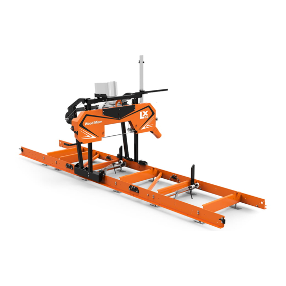
Safety Instructions Components See Figure 1-2. See the figure below for the operator’s work-place. FIG. 1-2 1.15 Components See Figure 1-3. The major components of the LX50EH7S sawmill are shown below. Log Clamp Water Tank Sawmill Mast Control Box Sawmill Frame Blade Motor Saw Head FIG. - Page 32 Safety Instructions Components See Figure 1-4. See the figure below for the main components of LX50G14S sawmill. Sawmill Frame Water Tank Sawmill Mast Blade Engine Log Side Support Log Clamp Sawdust Chute Saw Head FIG. 1-4 1-19 doc032021 Safety Instructions...
-
Page 33: Sawmill Assembly
SAWMILL ASSEMBLY Mounting Parts of LX50 Sawmill SECTION 2 SAWMILL ASSEMBLY Scan to see the assembly video. Mounting Parts of LX50 Sawmill 2.1.1 Parts Specifications Table 1: Fig. Wood-Mizer Description LX50 LX50 Electric 514996-1 Bed Foot, Com- plete Stud w/Rod, Log... - Page 34 SAWMILL ASSEMBLY Parts Specifications Table 1: 516939 Key, A6x6x14 Parallel 519161 Key, A6x6x22 Parallel 532328-1 Bushing, Winch Friction Pad 532329 Washer, Fric- tional 532331-1 Plate, Clamping 531997-1 Crank, LX50 532332 Bushing, Slide 532319-1 Sprocket, LX50 532365 Chain, L=939 73-Link 091625 Link, Master 531988-1 Plate, Support...
- Page 35 SAWMILL ASSEMBLY Parts Specifications Table 1: 531989-1 Plate, Main Sup- port 532313-1 Blade Height Scale Assembly 532325 Bushing, Winch Shaft Right 534526 Bushing, Winch Shaft Left 532306 Roller, Winch Guide X100-1273 Plate, Bent X100-1272 Plate, Flat X100-1275 Block, Stop X100-1155 Plate, Flat 014151 SAWMILL ASSEMBLY...
-
Page 36: Specifications Of Fasteners
F81082-5 Tie Wrap, 4.8x240mm LX50G/E Bolt Kit 1 kit 1 kit 1 kit 1 kit 2.1.2 Specifications of Fasteners Table 2: Wood-Mizer No Description LX50 LX50 Electric Designations of fasteners: M8 Nut 8.4 Washer M8x20 Bolt Bracket, Scale 530667 F81000-10 BOLT, M5x35 8.8 HEX HEAD... - Page 37 SAWMILL ASSEMBLY Specifications of Fasteners Table 2: F81032-2 NUT, M8-8-B HEX NYLON ZINC LOCK F81053-1 WASHER, 6.4 FLAT ZINC F81054-1 WASHER, 8.4 FLAT ZINC Sawdust Chute F81000-13 SCREW, M5X10 8.8 CROSS RECESSED PAN HEAD ZINC F81030-2 NUT, M5-8 DIN 985 ZINC-PLATED F81052-1 WASHER, 5.3 FLAT ZINC...
- Page 38 SAWMILL ASSEMBLY Specifications of Fasteners Table 2: F81055-1 WASHER, 10.5 ZINC FLAT Hanger, Power Cord F81087-2 Clip, 1.20/20 Retaining BOLT, M8x25-8.8 HEX HEAD F81002-5 FULL THREAD ZINC F81032-2 NUT, M8-8-B HEX NYLON ZINC LOCK F81054-1 WASHER, 8.4 ZINC FLAT Log Side Support, LX50 F81001-9 BOLT, M6x60-8.8 HEX HEAD FULL THREAD ZINC...
-
Page 39: Tools Necessary For Assembling The Sawmill
SAWMILL ASSEMBLY Tools Necessary for Assembling the Sawmill Table 2: Foot, Bed 514997 F81037-1 NUT, M20-8- HEX ZINC F81059-2 WASHER, 21 2.1.3 Tools Necessary for Assembling the Sawmill Table 3: Required tools Flat Wrench #8 1 pc Flat Wrench #10 2 pcs Flat Wrench #13 2 pcs... - Page 40 SAWMILL ASSEMBLY Unpacking the Sawmill See figure 2-1. FIG. 2-1 1. Cut the bands holding the components together. 2. Unbolt frame segments from the pallet. Remove all sawmill parts from the pallet and put them on the level surface. WARNING! When removing the saw head, use extreme care and keep all persons at a safe distance.
-
Page 41: Bed Frame Assembly
SAWMILL ASSEMBLY Bed Frame Assembly Bed Frame Assembly IMPORTANT! When assembling the sawmill, do not tighten the bolts/screws too much at the begining. The fasteners should be tight- ened fully only when all parts are already mounted. CAUTION! Assemble the sawmill bed on firm, level ground. Failure to do so may cause the saw head to tip, resulting in serious injury or death. - Page 42 SAWMILL ASSEMBLY Bed Frame Assembly 3. Connect the bed sections using the connecting plate, clamp and bolts shown in Figure 2-5. Set the clamp in place by inserting the smaller notch in first and tilting the clamp downward to ...
-
Page 43: Log Clamp And Side Support Installation
SAWMILL ASSEMBLY Log Clamp and Side Support Installation Log Clamp and Side Support Installation 1. To mount the log clamp, first dismount the mounting bracket on one side of the log clamp rod, insert the log clamp arm onto the rod and side support and reinstall the mounting bracket with M10x20 bolts. -
Page 44: Stop Blocks Installation
SAWMILL ASSEMBLY Stop Blocks Installation Stop Blocks Installation 1. Install the stop blocks at both ends of the bed to prevent the saw head from sliding off the bed. Attach the stop blocks on the outside surfaces of the front and last bed sections. Use M10x30 bolts. -
Page 45: Bed Leveling
SAWMILL ASSEMBLY Bed Leveling Bed Leveling 1. Use a min. 4-foot (120cm) level (or laser level) to level the bed in all directions. CAUTION! It is important that the bed be level for the saw head to travel smoothly over the rails. See figure 2-9. -
Page 46: Saw Head Installation
SAWMILL ASSEMBLY Saw Head Installation Saw Head Installation WARNING! When removing the saw head, use extreme care and keep all persons at a safe distance. Failure to do so may result in serious injury or death. 1. Before installation of the mast tubes, loosen the mounting bolts located on four mast guide brackets. - Page 47 SAWMILL ASSEMBLY Saw Head Installation 2. Connect the left and right mast tubes with the upper mast tube before inserting them into the guide brackets. To do this, insert the upper mast tube into the brackets and tighten using the M10x80 bolts.
- Page 48 SAWMILL ASSEMBLY Saw Head Installation 3. Insert the connected tubes into the mast guide brackets. The saw head should be placed vertically and stable on the table. Fasten the mast guide brackets so that they are a little loose for the mast to move properly.
- Page 49 SAWMILL ASSEMBLY Saw Head Installation SAWMILL ASSEMBLY 15doc032021 2-17...
- Page 50 SAWMILL ASSEMBLY Saw Head Installation 5. The saw head should be set at the top position on the mast so that you can easily access the bottom ends of the vertical mast tubes and the holes at half the height of the tubes. Install the head-locking stop pins in these holes on both tubes.
- Page 51 SAWMILL ASSEMBLY Saw Head Installation 7. Loosen M10x30 roller set. Using lifting equipment, place the saw head with the mast on the sawmill bed. Make sure the track rollers ride smoothly on the track rail. Then position the saw head at the front of the bed to secure it with a locking pin that will prevent accidental saw head movement.
- Page 52 SAWMILL ASSEMBLY Saw Head Installation 8. Install the electric box to the sawmill mast using the (A) M8x75 bolts. Bolt the electric box plate bracket to the sawmill mast using (B) M8x70 bolts. 9. Adjust the track wiper so that the felt touches the track rail surface and the saw head moves freely on the bed.
- Page 53 SAWMILL ASSEMBLY Saw Head Installation 10. To mount up/down system, first insert the plastic bushings into the holes located on up/down brackets. 11. Use (A) M8x25 and (B) M8x70 bolts to install the up/down bracket near the control box. SAWMILL ASSEMBLY 15doc032021 2-21...
- Page 54 SAWMILL ASSEMBLY Saw Head Installation 12. Insert the key (1) into the slot in the winch shaft. Slide the sprocket onto the shaft and tighten the screw (2) to prevent the sprocket from slipping off the shaft. Install the bushings at the other side of the shaft, as shown below.
- Page 55 SAWMILL ASSEMBLY Saw Head Installation Install the chain on the dial and insert the crank shaft through the hole in the dial. Install the other end of the chain on the winch shaft sprocket and connect the chain ends with the master link. Make sure the crank handle is bolted parallel to the dial.
- Page 56 SAWMILL ASSEMBLY Saw Head Installation 13. Mount the cable guide roller and secure with the washers and M8 nut as shown in the figure below. Repeat on the other side of the machine. 14. Thread the end of the steel lift cable through the hole in the mast (from the bottom). Lock the cable in place using the washer and M10 nut as shown below.
- Page 57 SAWMILL ASSEMBLY Saw Head Installation 15. Remove the head-locking stop pins from both vertical mast tubes to lower the saw head all the way down. When the saw head is at its lowest position, route the lift cable as it is shown below. Next, route the lift cable through the hole in the winch shaft bushing.
- Page 58 SAWMILL ASSEMBLY Saw Head Installation 16. Install the saw head cover latch using two M8x20 bolts. 2-26 15doc032021 SAWMILL ASSEMBLY...
-
Page 59: Sawdust Chute Assembly
SAWMILL ASSEMBLY Sawdust Chute Assembly Sawdust Chute Assembly 1. Open the saw head cover and fasten the sawdust chute using the (A) M5x12 and (B) M5x10 bolts. See figure 2-12. FIG. 2-12 SAWMILL ASSEMBLY 15doc032021 2-27... -
Page 60: Water Bottle Installation
SAWMILL ASSEMBLY Water Bottle Installation Water Bottle Installation 1. Install the water bottle tray to the mast cross tube using the M8x70 bolts. Before bolting, place a cable clamp on one of the hex head bolts. See figure 2-13. FIG. 2-13 2. - Page 61 SAWMILL ASSEMBLY Water Bottle Installation 3. Attach the power cord bracket (A) to the mast tube (B). Use bolts to screw them together. See figure 2-15. FIG. 2-15 4. Install the power cord (A) on the mast using the cable clamps (B). See figure 2-16.
-
Page 62: Blade Height Scale Installation
SAWMILL ASSEMBLY Blade Height Scale Installation 2.10 Blade Height Scale Installation 1. Open the saw head cover to install the blade height scale. Use (A) M8x20 bolts to attach blade height scale to the saw head cover. Bolt the scale guide blocks on both edges of the scale using (B) M6x30 bolts. -
Page 63: Catch Rail Installation
SAWMILL ASSEMBLY Catch Rail Installation 2.11 Catch Rail Installation 1. Place the safety catch rails along the sawmill bed and prepare the fasteners (M10x30 bolts, nuts and washers). Set the rails in proper position as shown below. First, bolt the A and B rails to the bed. -
Page 64: Clutch Lever Installation (Gas Sawmills)
SAWMILL ASSEMBLY Clutch Lever Installation (Gas Sawmills) 2.12 Clutch Lever Installation (Gas Sawmills) 1. Install the emergency stop button on the control box. See figure 2-17. FIG. 2-17 2. Bolt the clutch cable to the lever. The customer has to secure the clutch cable in its middle position for later adjustment. - Page 65 SAWMILL ASSEMBLY Clutch Lever Installation (Gas Sawmills) 3. Install the safety switch (Part No. 100910) to the clutch lever bracket using the two screws as shown below. See figure 2-19. FIG. 2-19 4. Install the safety switch to the clutch lever bracket using the four screws as shown below. Patrz rysunek 2-20.
- Page 66 SAWMILL ASSEMBLY Clutch Lever Installation (Gas Sawmills) See figure 2-21. RYS. 2-21 See figure 2-22. RYS. 2-22 2-34 15doc032021 SAWMILL ASSEMBLY...
- Page 67 SAWMILL ASSEMBLY Clutch Lever Installation (Gas Sawmills) See figure 2-23. See figure 2-24. SAWMILL ASSEMBLY 15doc032021 2-35...
- Page 68 SAWMILL ASSEMBLY Clutch Lever Installation (Gas Sawmills) See figure 2-25. See figure 2-26. 2-36 15doc032021 SAWMILL ASSEMBLY...
- Page 69 SAWMILL ASSEMBLY Clutch Lever Installation (Gas Sawmills) See figure 2-27. SAWMILL ASSEMBLY 15doc032021 2-37...
-
Page 70: Sawmill Operation
Sawmill Operation Safety Instructions SECTION 3 SAWMILL OPERATION Safety Instructions DANGER! Make sure that the motor/engine is off before performing any maintenance. Failure to do so may result in serious injury or death. DANGER! Keep all persons out of the path of moving equipment and logs when operating the sawmill or loading and turning logs. - Page 71 Sawmill Operation Sawmill Setup AC sawmills must not be used outdoors when it is raining or snowing. In such a case, they must be used and stored under roof or indoors. Gas sawmills must not be used indoors. Such sawmills can be operated outdoors without a ...
-
Page 72: Replacing The Blade
Sawmill Operation Replacing the Blade The LX50 sawmills are only partially aligned at the factory. Some assemblies need to be aligned by the user before first usage of the sawmill. Assemblies aligned at the factory: Engine r.p.m. (DC sawmills only), ... -
Page 73: Tensioning The Blade
Sawmill Operation Tensioning the Blade Tensioning the Blade See Figure 3-1. A wrench for tensioning the blade is located at the rear of the saw head. Place the wrench on the tensioner screw. Turn the tensioner screw right until the tension indicator is in the middle of the notch indicating the correct tension. -
Page 74: Tracking The Blade
Sawmill Operation Tracking the Blade Tracking the Blade After tensioning the blade, check its position on the blade wheels. See Figure 3-2. Position 1 1/4” (32 mm) wide blades on the blade wheels so the blade teeth are 9 -10 mm (±1 mm) out from the edge of the wheel. Make sure the rear edge of the blade is lying flat on the wheels and is no more than 3 mm out from the edges of the blade wheel belts. -
Page 75: Horizontal Adjustment Of Idle-Side Blade Wheel
Sawmill Operation Horizontal Adjustment of Idle-Side Blade Wheel Horizontal Adjustment of Idle-Side Blade Wheel First, adjust the idle-side blade wheel horizontally. To do this, loosen the set nuts on the adjustment bolts and tilt the blade wheel until it is properly aligned. See Figure 3-3. -
Page 76: Motor Drive Pulley Alignment
Sawmill Operation Motor Drive Pulley Alignment Motor Drive Pulley Alignment See Figure 3-4. Check that the motor drive pulley is aligned with the blade wheel using a ruler as shown below. FIG. 3-4 To align the pulleys, loosen or tighten the bolts in the motor mount plates on both sides of the motor. Incorrect pulley alignment may result in premature drive belt wear. -
Page 77: Vertical Adjustment Of Drive-Side Blade Wheel
Sawmill Operation Vertical Adjustment of Drive-Side Blade Wheel sure to tighten the nut after adjustment. Adjustment Screw Adjustment Screw FIG. 3-5 Vertical Adjustment of Drive-Side Blade Wheel The blade wheels must be square to the sawmill bed and parallel to each other in the vertical and horizontal planes. - Page 78 Sawmill Operation Vertical Adjustment of Drive-Side Blade Wheel bottom of the tool to the top surface of the bed rail. 3. Move the saw head so the rear of the tool is positioned over the bed rail. Again, measure from the bottom of the tool to the bed rail.
- Page 79 Sawmill Operation Vertical Adjustment of Drive-Side Blade Wheel See Figure 3-7. Use the screws shown below to adjust the drive blade wheel vertically. To tilt the wheel down, loosen the top adjustment screw a half turn. Loosen the jam nut on the bottom adjustment screw and tighten the screw.
-
Page 80: Vertical Adjustment Of Idle-Side Blade Wheel
Sawmill Operation Vertical Adjustment of Idle-Side Blade Wheel 3.10 Vertical Adjustment of Idle-Side Blade Wheel 1. Attach the alignment tool to the blade near the idle-side blade guide. 2. Measure from the bottom of the tool to the bed rail at both ends of the tool. If the measurements are not equal (±... - Page 81 Sawmill Operation Vertical Adjustment of Idle-Side Blade Wheel See Figure 3-9. The figure below shows the screws for positioning the blade on the blade wheels. FIG. 3-9 Sawmill Operation doc072221 3-12...
-
Page 82: Saw Head Adjustment
Sawmill Operation Saw Head Adjustment 3.11 Saw Head Adjustment 1. Check that the tensioned blade is parallel to a bed rail. To do this, measure the distance between the blade and the bed rail on both sides of the saw head. If the two measurements are not the same, adjust the saw head in relation to the bed on one or both sides, as necessary. -
Page 83: Blade Deflection
Sawmill Operation Blade Deflection 3.12 Blade Deflection Perform the following steps to achieve proper blade deflection with the blade guides: 1. Position the saw head so that the blade is above a bed rail. Measure the actual distance with a tape from the top of the rail to the bottom of the blade. -
Page 84: Blade Guide Vertical Adjustment
Sawmill Operation Blade Guide Vertical Adjustment 3.13 Blade Guide Vertical Adjustment Check that the blade guides does not tilt the blade up or down. A Blade Guide Alignment Tool is provided to help you measure the vertical tilt of the blade. 1. -
Page 85: Blade Guide Spacing Adjustment
Sawmill Operation Blade Guide Spacing Adjustment See Figure 3-13. Loosen jam nuts and turn screws to tilt roller up or down SM0070 FIG. 3-13 6. Move the saw head in the cutting direction so the back end of the tool is over the bed rail. Measure the distance between the tool and the bed rail. - Page 86 Sawmill Operation Blade Guide Spacing Adjustment See Figure 3-14. Loosen one top and one side set screw 1,5 - 3,0 mm Adjust spacing between roller and blade SM0071a FIG. 3-14 3. Tighten the set screws. 4. Repeat the above adjustment procedure for the other blade guide. NOTE: After adjusting the blade guide spacing, start the blade drive for a moment.
-
Page 87: Blade Guide Horizontal Adjustment
Sawmill Operation Blade Guide Horizontal Adjustment 3.15 Blade Guide Horizontal Adjustment See Figure 3-15. FIG. 3-15 1. Place the Blade Guide Alignment Tool against the face of a blade guide roller and center it on theroller as shown above. 2. Measure between the back edge of the blade and the tool at one end of the tool ("B"). 3. -
Page 88: Blade Height Scale Adjustment
Sawmill Operation Blade Height Scale Adjustment 3.16 Blade Height Scale Adjustment After the entire sawmill has been aligned and all adjustments made, check that the blade height scale indicates the true distance from the blade to the bed rails. See Figure 3-16. Loosen bracket mounting nuts FIG. -
Page 89: Engine/Motor Drive Belt Adjustment
Sawmill Operation Engine/Motor Drive Belt Adjustment 1. Move the saw head so the blade is positioned directly above one of the bed rails. Measure from the bottom edge on a down-set tooth of the blade to the top of the bed rail. 2. -
Page 90: Starting The Engine/Motor
Sawmill Operation Starting the Engine/Motor See Figure 3-18. Throttle Cable Tensioner Cable FIG. 3-18 3.18 Starting the Engine/Motor See the engine/motor manual supplied with your machine for starting and operating instructions. IMPORTANT! When starting the machine for the first time, check that main motor rotation direction is as indicated by the arrow located on the motor body. -
Page 91: Loading, Turning And Clamping Logs
Sawmill Operation Loading, Turning and Clamping Logs 3.19 Loading, Turning and Clamping Logs To load a log: 1. Move the saw head to the front end of the frame. CAUTION! Before loading a log, be sure the saw head is moved far enough forward so the log does not hit it. - Page 92 Sawmill Operation Loading, Turning and Clamping Logs See Figure 3-19. FIG. 3-19 3. Make sure the side supports are positioned low enough for the blade to pass over them. If they are not, back the clamp off slightly and push the side supports down until they are positioned below the height of your last cut on a given side of the log.
-
Page 93: Up/Down Operation
Sawmill Operation Up/Down Operation 3.20 Up/Down Operation 1. Install a blade, if needed, and check for correct blade tension. 2. Using the crank handle, set the saw head to the desired height (the blade height scale shows the height of the blade above bed rails). One full turn of the crank handle moves the saw head 12.21 mm. - Page 94 Sawmill Operation Blade Drive Operation For Sawmills with the Electric Motor 1. Clear any loose objects from the area of the blade, motor, and drive belt. 2. Make sure the clamps and side supports are positioned low enough for the blade to pass over them. Make sure the log is clamped securely.
-
Page 95: Gas Engine Operation (G14)
Sawmill Operation Gas Engine Operation (G14) 3.22 Gas Engine Operation (G14) WARNING! Do not start the engine if the drive belt tensioner handle is ENGAGED. Always be sure the blade is disengaged and all persons are out of the path of the blade before starting the engine. IMPORTANT! Read the engine manual for instructions and safety precautions before operating the engine. - Page 96 Sawmill Operation Gas Engine Operation (G14) engine. 7. Cold engine: When the engine starts, slowly open the choke all the way by moving the choke leverto the “OFF” position. 8. Press and hold the safety handle (CE sawmills only). 9. Engage the tensioner handle by pushing it toward you as shown below. See Figure 3-24.
-
Page 97: Feed Operation
Sawmill Operation Feed Operation Engine Shutoff 1. Disengage the tensioner handle (by moving it away from you) to stop the blade. 2. The engine should run with no load for 15 seconds. Stop the engine by moving the ignition/fuel lever to the ”OFF”... -
Page 98: Cutting The Log
Sawmill Operation Cutting the Log 3.24 Cutting the Log The following steps guide you through normal operation of the LX50 sawmill. 1. Once the log is placed where you want it and clamped firmly, position the blade close to the end of the log. -
Page 99: Edging
Sawmill Operation Edging 3.25 Edging The following steps guide you through edging boards on the LX50 sawmill. 1. Raise the side supports to 1/2 the height of the boards that need to be edged. 2. Stack these boards on edges against the side supports. 3. -
Page 100: Stop Bolt Adjustment
Sawmill Operation Stop Bolt Adjustment Scale The blade height indicator shows how many centimeters the bottom of the blade is above the bed of the sawmill. If you know the height of your blade at each cut, you can determine the thickness of lumber you are sawing. -
Page 101: Water Lube System
Sawmill Operation Water Lube System 3.28 Water Lube System The Water Lube System keeps the blade clean during sawing. Water flows from a 5-gallon (18.9 liter) bottle through a hose to the blade guide where the blade enters the log. A valve in the bottle cap controls the amount of water flow. -
Page 102: Transporting The Sawmill
Sawmill Operation Transporting the Sawmill 3.29 Transporting the Sawmill The assembled sawmill can be transported in an appropriately equipped pickup truck. 1. Move the saw head to one of the segments equipped with the stop block and secure it in place with the locking pin. -
Page 103: Troubleshooting
Sawmill Operation Transporting the Sawmill 3.30 Troubleshooting DANGER! Before performing any service to this machine, turn off the motor/engine and remove the key. Moving sawmill parts can cause serious injury or death. PROBLEM CAUSE SOLUTION Blades dull quickly Dirty logs Clean or debark logs, especially on entry side of the cut. - Page 104 Sawmill Operation Transporting the Sawmill Height adjustment jumps Lift cable improperly Adjust the lift cable. or stutters when moving up adjusted or down Vertical wear pads are too Adjust pads. tight. Lift cable too loose Replace/adjust lift cable. Lumber is not square Vertical side supports not Adjust side supports.
-
Page 105: Maintenance
Maintenance Mast Track, Rollers and Wipers SECTION 4 MAINTENANCE WARNING! Before removing any cover or guard, always turn off the motor/engine and wait until all parts have stopped moving. Failure to do so may result in serious injury or death. Maintenance Performed as Needed Mast Track, Rollers and Wipers Properly maintaining the mast track surfaces and the track rollers is critical in preventing corrosion that... -
Page 106: General Maintenance
Maintenance General Maintenance See Figure 4-2. Mast Track Surface FIG. 4-2 General Maintenance Every 8 Hours of Sawmill Operation Check the engine oil level. (See the Engine Manual.) Clean the track rollers, mast carriages and track wipers. After you have finished using the sawmill, lower the saw head all the way down so that the saw ... - Page 107 Maintenance See Figure 4-3. FIG. 4-3 Monthly (every 160 hours of sawmill operation) Apply white lithium grease to the lift cables on both sides of the saw head. CAUTION! Check if the lift cables are in good condition. If either lift cable is damaged, immediately replace it with a new one.
-
Page 108: Motor/Engine Maintenance
Maintenance Motor/Engine Maintenance See Figure 4-4. Lubricate lift cables FIG. 4-4 Motor/Engine Maintenance Refer to the motor/engine manufacturer’s manual for maintenance intervals and procedures regarding the motor/engine. doc032021 Maintenance... - Page 109 WOOD-MIZER LT15WCSC/LX100/LX450 MAINTENANCE LOG (Check Engine And Option Manuals For Additional Maintenance Procedures) PROCEDURE MANUAL REF- TOTAL HOURS OF OPERATION ERENCE FILL IN THE DATE AND THE MACHINE HOURS AS YOU PERFORM EACH PROCEDURE. A SHADED BOX INDICATES MAINTENANCE IS NOT NEEDED AT THIS TIME.
- Page 110 WOOD-MIZER LT15WCSC/LX100/LX450 MAINTENANCE LOG (Check Engine And Option Manuals For Additional Maintenance Procedures) PROCEDURE MANUAL REF- TOTAL HOURS OF OPERATION ERENCE FILL IN THE DATE AND THE MACHINE HOURS AS YOU PERFORM EACH PROCEDURE. A SHADED BOX INDICATES MAINTENANCE IS NOT NEEDED AT THIS TIME.
- Page 111 WOOD-MIZER LT15WCSC/LX100/LX450 MAINTENANCE LOG (Check Engine And Option Manuals For Additional Maintenance Procedures) PROCEDURE MANUAL REF- TOTAL HOURS OF OPERATION ERENCE FILL IN THE DATE AND THE MACHINE HOURS AS YOU PERFORM EACH PROCEDURE. A SHADED BOX INDICATES MAINTENANCE IS NOT NEEDED AT THIS TIME.
- Page 112 30doc122921...
- Page 113 EC declaration of conformity according to EC Machinery Directive 2006/42/EC, Annex II, 1.A Manufacturer: Wood-Mizer Industries Sp. z o. o. 114 Nagórna; 62- Tel. +48 63 26 26 000 This declaration of conformity is issued under the sole responsibility of the manufacturer.
Need help?
Do you have a question about the LX50 EH7S and is the answer not in the manual?
Questions and answers
Blade turns when not engaged
The Wood-Mizer LX50 EH7S blade may turn when not engaged due to residual tension in the blade system, misalignment of blade wheels, or issues with the blade tensioner screw. Checking and adjusting the blade tension and alignment as per the manual instructions can help resolve this issue.
This answer is automatically generated