Table of Contents

Related Manuals for Wood-mizer LX150


Summary of Contents for Wood-mizer LX150
- Page 1 ® Wood-Mizer Sawmill Safety, Setup, Operation & Maintenance Manual LX150 rev. A3.01+ Safety is our #1 concern! Read and understand all safety information and instructions before oper- ating, setting up or maintaining this machine. Form #2272...
- Page 2 Active Patents assigned to Wood-Mizer, LLC Wood-Mizer, LLC has received patents that protect our inventions which are a result of a dedication to research, innovation, development, and design. Learn more at: woodmizer.com/patents ©2020 Wood-Mizer LLC Printed in the United States of America, all rights reserved. No part of this manual may be reproduced in any form by...
-
Page 3: Table Of Contents
Table of Contents Section-Page SECTION 1 INTRODUCTION About This Manual.................1-1 Getting Service ..................1-1 Specifications ..................1-1 Customer and Sawmill Identification.............1-1 Specifications ..................1-3 LX150 Dimensions ................. 1-4 SECTION 2 SAFETY Safety Symbols..................2-5 Safety Instructions ..................2-5 Electrical Lockout Procedures..............2-10 SECTION 3 SAWMILL ASSEMBLY Tools required..................3-1 Uncrating the mill...................3-2... - Page 4 Table of Contents Section-Page Water Lube Operation ................5-10 Transporting the Sawmill ..............5-11 SECTION 6 MAINTENANCE Wear Life....................6-1 Blade Guides ..................6-1 Changing The Blade ................6-2 Sawdust Removal ...................6-3 Mast Track, Wipers, & Scrapers ............6-4 Vertical Mast Rails .................6-5 Miscellaneous ..................6-5 Drive Belt Adjustment................6-6 Up/Down System..................6-8 6.10 Charging The Battery ................6-9...
- Page 5 Limited Product Warranty Wood-Mizer LLC (“Warrantor”), an Indiana corporation with its principal place of business at 8180 West Tenth Street, Indianapolis, IN 46214-2400 USA, warrants to the purchaser (“Purchaser”) that for the time periods specifically stated herein and subject to the terms, conditions and limitations stated herein, the equipment manufactured by the Warrantor will be free from defects in material and workmanship attributable to Warrantor so long as, during the warranty periods stated herein, the equipment is installed, operated and maintained in accordance with the instructions provided by Warrantor.
-
Page 6: Introduction
Customer and Sawmill Identification Each Wood-Mizer sawmill is identified with a model number, revision, and serial number (see the figure below). M FG B Y / FA B R IQ U É PA R : W O O D -M IZ ER P R O D U C TS , IN C . 8 18 0 W. 1 0th St. Ind ian ap olis , 4 62 1 4 -2 40 0 U .S .A . - Page 7 Introduction Customer and Sawmill Identification The model number includes the base model and the engine/motor configuration. The serial num- ber contains the month and year of manufacture and a sequence number. The revision number helps identify the exact design of the equipment. LX250 Model Number Engine/Motor...
-
Page 8: Specifications
Introduction Specifications Specifications Model: LX150 Rev. A1.00+ Dimensions: Length: 218.5” 18’-2.5” Width: 100” 8’-4” Height (Ground To Mast): 6’-4.75” (not including 4” legs) Height (Max Head Position): 7’-2” (not including 4” legs) Weights (Estimated): Basic Unit : Log Capacity: Length: 18 5”... -
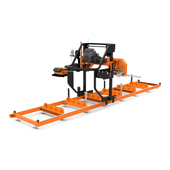
Page 9: Lx150 Dimensions
Introduction LX150 Dimensions LX150 Dimensions WMdoc120220... -
Page 10: Safety
NOTICE: The procedures listed in this manual may not include all ANSI, OSHA, or locally required safety procedures. It is the owner/operator’s responsibility and not Wood-Mizer Products to ensure all operators are properly trained and informed of all safety protocols. Owner/Operators are responsible for following all safety procedures when operating and per- forming maintenance to the Sawmill. - Page 11 Wood-Mizer sawmill. All Wood-Mizer mill owners are encouraged to become thoroughly familiar with these applica- ble laws and comply with them fully while using the mill.
- Page 12 Failure to follow this may result in serious injury or death. WARNING! Use ONLY water and Wood-Mizer Lube Additive with the water lube accessory. Never use flammable fuels or liquids such as diesel fuel. If these types of liquids are necessary to clean the blade, remove it and clean with a rag.
- Page 13 Safety Safety Instructions EMERGENCY TREATMENT FOR CONTACT WITH BATTERY COMPONENTS (LEAD/SUL- FURIC ACID) per SDS (Safety Data Sheet): EYE CONTACT Sulfuric Acid and Lead: Flush eyes immediately with large amounts of water for at least 15 minutes while lifting lids. Seek immediate medical atten- tion if eyes have been exposed directly to acid.
- Page 14 Safety Safety Instructions Be sure the blade housing and pulley covers are in place and secure. Use the safety retainer pin and cable to fasten blade housing covers. WARNING! Do not operate the sawmill without the retaining (stop bumper) bracket properly installed on the bed. The saw head may tip and fall from the sawmill.
-
Page 15: Electrical Lockout Procedures
Safety Electrical Lockout Procedures WARNING! Keep hands, feet, and other objects away from the sawdust chute when operating sawmill. Failure to follow this may result in serious injury or death. CAUTIONS FOR GAS OR DIESEL ENGINE OPERATION DANGER! Operate your engine/machine only in well ventilated areas. Failure to follow this will result in serious injury or death. - Page 16 Safety Electrical Lockout Procedures LOCKOUT PROCEDURES MUST BE USED DURING: Changing or adjusting blades Electrical maintenance Unjamming operations Retrieval of tools/parts from work area Cleaning Activities where guards or electrical panel guard is open or removed Mechanical repair Table 1: MAINTENANCE HAZARDS INCLUDE: Blade contact Missiles (thrown blades/wood chips)
- Page 17 Safety Electrical Lockout Procedures This procedure establishes the minimum requirements for the lockout of energy isolating devices whenever maintenance or servicing is done on machines or equipment. It shall be used to ensure that the machine or equipment is stopped, isolated from all potentially hazardous energy sources and locked out before personnel perform any servicing or maintenance where the unex- pected enervation or start-up of the machine or equipment or release of stored energy could cause injury.
- Page 18 Safety Electrical Lockout Procedures 1. Check the machine or equipment and the immediate area around the machine to ensure that nonessential items have been removed and that the machine or equipment components are operationally intact. 2. Check the work area to ensure that all personnel have been safely positioned or removed from the area.
-
Page 19: Sawmill Assembly
Sawmill Assembly Tools required SECTION 3 SAWMILL ASSEMBLY CAREFUL PLANNING IS ESSENTIAL TO A SMOOTH ASSEMBLY. READ THIS SECTION THOROUGHLY TO PLAN THE ASSEMBLY. IMPORTANT! Do not unbolt all the shipping brackets at once. Remove the shipping brackets securing the sawmill to the pallet at each step to prevent inadvertent shifting of the parts. -
Page 20: Uncrating The Mill
Sawmill Assembly Uncrating the mill Uncrating the mill See Figure 3-1. FIG. 3-1 1. Remove any shipping straps or plastic coverings from the mill before beginning. 2. Remove and inspect the parts boxes. (See Table 1.) NOTE: If the saw head blocks the parts boxes, the head can be raised using the operator’s control. - Page 21 Sawmill Assembly Uncrating the mill TABLE 1: PARTS BOX CONTENTS Part # Description Image Rail Wiper Assemblies 517609 Wiper 517610-1 Wiper Plate F05020-6 Bolt, M6-1x20 HH Class 8 F05026-2 Washer, M6 Split Lock F05026-1 Washer, M6 Flat Class 4 Bed Feet Assembly F81037-1 Nut, M20-8 Hex Zinc F81059-2...
- Page 22 Sawmill Assembly Uncrating the mill TABLE 1: PARTS BOX CONTENTS Part # Description Image Idle Side Bed Stop Assem- bly, Front Back Orientation 516075-1 Plate, Bed Stop 515061-1 Plate, Bed Stop Shim P12165 Bushing, Bed Stop 086182-1 Bolt, Bed Stop F81043-2 Pin, Roll S-Zn 4x25 PN-M/82001...
- Page 23 Washer, M10 Flat F05022-22 Bolt, M10-1.5x90 Hex Head Class 8 F05004-27 Nut, M10-1.50 Hex Nyl Lock Mast Safety Assemblies 011119 Plate, LX150 Mast Safety P13576 Pad, Catapillar Track F05021-2 Bolt, M8-1.25x20 Class 8 HH 507563 Bolt, Clamp Complete Sawmill Assembly...
-
Page 24: Pre-Assemble The Legs
Sawmill Assembly Pre-assemble the legs TABLE 1: PARTS BOX CONTENTS Part # Description Image 515413-1 Wedge 4. Open the parts box and spread the parts out in on orderly fashion. See Figure 3-2. See Figure 3-2. FIG. 3-2 5. Ensure all the parts are present. Pre-assemble the legs 1. -
Page 25: Unpack The Saw Head
Sawmill Assembly Unpack the saw head See Figure 3-3. All nuts at the same level to aid in assembly and leveling LX15042 FIG. 3-3 3. Place the small bed section at the end of the designated area for the mill assembly. IMPORTANT! Observe the direction of the alignment pins in relation to the remaining bed... -
Page 26: Assemble The Log Bed
Sawmill Assembly Assemble the log bed See Figure 3-4. LX15041-01 FIG. 3-4 Assemble the log bed WARNING! Use a minimum of two people to remove the bed sections from the packing crate. Failure to fol- low this may result in serious injury. 1. - Page 27 Sawmill Assembly Assemble the log bed 3. Lay the first and second bed sections end-to-end so the track alignment pins of each sec- tion align with the section in front of it. 4. Slide the sections together as shown in Figure 3-6. See Figure 3-6.
-
Page 28: Bumper Assemblies
Sawmill Assembly Bumper Assemblies See Figure 3-7. LX1501-12 FIG. 3-7 9. Loosen the upper nut on the feet, then use lower nut to adjust the sawmill bed height; retighten the upper nut. See Figure 3-8. Tighten Set height LX1501-11 FIG. 3-8 10. -
Page 29: Install Travel Locks
Sawmill Assembly Install Travel Locks See Figure 3-9. Log support Large bumper Large bumper LX1501-10 FIG. 3-9 1. Mount the bumpers to the frame with the shims between the frame and the bumpers. See Figure 3-10. F81037-1, M20-8 nut F81055-1, M10.5 flat 515061-1, Shim F81037-1, M20-8 nut LX15041-12... -
Page 30: Leveling The Bed
Sawmill Assembly Leveling the bed 1. Remove the F81003-50 M10x80mm mounting bolts for the log support/clamp one bed section. 2. Remount the log support/clamp and the travel lock with the longer F05022-22 M10x90mm and the F05004-270 M10 nylock nuts. See Figure 3-11. F05022-22, M10x90mm F05004-270 M10 nylock nuts LX15041-13... -
Page 31: Saw Mast Assembly
Sawmill Assembly Saw Mast Assembly See Figure 3-12. Measure the distance between the string and the bed rails Matching Spacer String Matching Spacer LX1501-05 LX1501-05 LX1501-05 FIG. 3-12 6. Repeat the bed rail adjustment with the string at the other side of the sawmill frame. Saw Mast Assembly IMPORTANT! Do not attempt to set the carriage down on any surface... - Page 32 Sawmill Assembly Saw Mast Assembly See Figure 3-13. F05021-2, M8 bolts LX1501-13 FIG. 3-13 6. Install all four the rail wipers on the mast rollers as shown in Figure 3-14. The wiper should fit snuggly on the rail while the mount should stay 1/8” above the rail. See Figure 3-14.
-
Page 33: Feed Drive Rope Assembly
Sawmill Assembly Feed Drive Rope Assembly See Figure 3-15. Fuel input line Return line LX15041-16 FIG. 3-15 8. Fill the water and fuel tank. Feed Drive Rope Assembly 1. Thread one end of the feed rope through the bumper bracket at the front end of the bed assembly. - Page 34 Sawmill Assembly Feed Drive Rope Assembly NOTE: The pulleys may be difficult to access, but it is not necessary to remove any parts. See Figure 3-17. Pulleys are located between the bed frame feed drive motor LX15041-03 FIG. 3-17 5. Assemble the feed rope eyebolt in the rear bumper bracket as shown in Figure 3-18. 6.
-
Page 35: Install The Blade
Sawmill Assembly Install the Blade Install the Blade DANGER! COILED BLADES ARE UNDER SPRING TENSION. KNOW PROPER BLADE HANDLING BEFORE UNPACKING YOUR BLADE. FAILURE TO FOLLOW THIS WILL RESULT IN SERIOUS INJURY. WARNING! Wear gloves and eye protection when handling bandsaw blades. - Page 36 Sawmill Assembly Install the Blade See Figure 3-19. Tensioner handle (storage area) Tensioner handle LX1501-04 FIG. 3-19 5. Carefully remove and uncoil the blade from the shipping box. 6. Place the new blade around the blade wheels. NOTE: When installing a blade, make sure the teeth are pointing the correct direction.
- Page 37 Sawmill Assembly Install the Blade Sawmill Assembly WMdoc041521 3-19...
-
Page 38: Sawmill Setup
Sawmill Setup Installing the Blade SECTION 4 SAWMILL SETUP The following setup procedure should be performed whenever the sawmill is moved or reassembled. If sawing problems occur and misalignment is suspected, See Section SECTION 8 for complete alignment instructions. See Section SECTION 8 for sawmill assembly instructions. - Page 39 Sawmill Setup Installing the Blade See Figure 4-1. Tensioner handle (storage area) Tensioner handle LX1501-04 FIG. 4-1 3. Place the new blade around the blade wheels. NOTE: When installing a blade, make sure the teeth are pointing the correct direction. The teeth should be pointing toward the operator side of the mill when you are looking at the blade below the blade guides.
-
Page 40: Tensioning The Blade
Sawmill Setup Tensioning The Blade Tensioning The Blade 1. Use the supplied handle to turn the tensioner handle clockwise until the tension gauge indicates 1500-1700 PSI tension. See Figure 4-2. Tensioner handle (storage area) Tension gauge Normal operation: 1500-1700 PSI Tensioner handle LX1501-04 FIG. - Page 41 Sawmill Setup Tracking The Blade 1. Ensure the blade housing cover is closed and all persons are clear of the open side of the saw head. DANGER! Always be sure the blade is disengaged and all persons are out of the path of the blade before starting the engine or motor. Failure to follow this will result in serious injury WARNING! Make sure all guards and covers are in place and secured...
- Page 42 Sawmill Setup Tracking The Blade See Figure 4-4. Cant Control LX1501-07 FIG. 4-4 7. Position 1 1/4” wide blades so the gullet is 1/8" (3.0 mm) out from the edge of the blade wheel (±1/32 [.75 mm]). See Figure 4-5. 150060 1/8”...
-
Page 43: Sawblade
Sawmill Setup Sawblade WARNING! Make sure all guards and covers are in place and secured before operating the sawmill. Failure to follow this may result in serious injury or death. NOTICE: After aligning the blade on the wheels, always double-check the blade guide spacing and location. -
Page 44: Blade Guide Flange Spacing
Sawmill Setup Blade Guide Flange Spacing 7. Measure the distance from the bed rail to the bottom edge of the tool. 8. If the measurement from the tool to the bed rail is not equal within 1/32" (.75 mm), adjust the vertical tilt of the outer blade guide roller. - Page 45 Sawmill Setup Blade Guide Flange Spacing The blade guide rollers should also be slightly cocked. If the moving blade makes contact with the leading flange edge of the roller, momentum may cause the blade to slip over the flange. Contact with the trailing edge would force the blade upward onto the roller. NOTICE: When adjusting blade guide spacing, loosen the top set screw and one side set screw only.
-
Page 46: Starting The Engine
Sawmill Setup Starting The Engine INNER BLADE GUIDE 6. Ensure that the distance between the flange on the inner blade guide roller to the back edge of the blade measures to 1/16" (1.5 mm). See Figure 4-8. 7. Adjust the roller back or forward, as described above. Starting The Engine DANGER! Always be sure the blade is disengaged and all persons are... -
Page 47: Sawmill Operation
Sawmill Operation Power Feed SECTION 5 SAWMILL OPERATION Power Feed The power feed system moves the carriage forward and backward by using the two switches on the control panel illustrated below. See Figure 5-1. Fast Forward Slow Reverse Drum Switch LX0017-1 FIG. - Page 48 Sawmill Operation Power Feed CARRIAGE FEED RATE The carriage feed rate switch controls the speed at which the carriage travels forward. Turn the switch clockwise to increase speed. Turn it counterclockwise to reduce speed. USING THE POWER FEED 1. Use the forward/reverse drum switch and the feed rate switch to position the sawhead for the cut.
-
Page 49: Up/Down Operation
Sawmill Operation Up/Down Operation DANGER! Stay clear of the area between the trailer axle and saw car- riage. Failure to follow this will result in death or serious injury. Up/Down Operation CAUTION! Ensure the blade is properly installed and tensioned before moving the sawhead. -
Page 50: Loading, Turning, & Clamping Logs
Sawmill Operation Loading, Turning, & Clamping Logs Loading, Turning, & Clamping Logs LOADING LOGS 1. Move the saw carriage to the front end of the frame. CAUTION! Before loading a log, be sure the cutting head is moved far enough forward so the log does not hit it. Failure to follow this may result in machine damage. - Page 51 Sawmill Operation Loading, Turning, & Clamping Logs CLAMPING LOGS CAUTION! Make sure the side supports and clamp are positioned low enough for the blade to pass over them. If they are not, back the clamp off slightly and push the side supports down until they are positioned below the level of your first few cuts.
-
Page 52: Blade Guide Arm Operation
Sawmill Operation Blade Guide Arm Operation See Figure 5-4. Raise log until the heart is parallel with the log bed Leveling wedge LX1503-05 FIG. 5-4 Blade Guide Arm Operation 1. Set the outer blade guide to clear the widest section of the log by less than 1" (25.4 mm). 2. -
Page 53: Cutting The Log
Sawmill Operation Cutting The Log See Figure 5-5. LX0018-06 FIG. 5-5 4. Use the blade guide toggle switch to readjust the outer blade guide as you are cutting in order to keep the guide within 1" (2.5 cm) of the log. 5. -
Page 54: Edging
Sawmill Operation Edging 6. When the teeth exit the end of the log, disengage the clutch and remove the cut slab. 7. Return the carriage to the front of the mill. 8. Repeat until the first side of the log is cut as desired. 9. -
Page 55: Blade Height Scale
Sawmill Operation Blade Height Scale 7. Loosen the clamps and remove the boards that have good clean edges on both sides. Clamp the remaining flitches and repeat steps 2-5. Blade Height Scale See Figure 5-6. LX1501-21 FIG. 5-6 THE INCH SCALE The horizontal line on the blade height indicator shows how many inches the bottom of the blade is above the bed of the mill. -
Page 56: Water Lube Operation
Sawmill Operation Water Lube Operation Scale Actual Board Thickness 1" (25 mm) 1 1/4" (32 mm) 1 1/2" (38 mm) 2" (51 mm) TABLE 5-1 To use the quarter scale, look at the blade height indicator. Position the magnetic quarter scale over the inch scale. Align one of the quarter scale marks with the horizontal line on the indicator. -
Page 57: Transporting The Sawmill
Transporting the Sawmill THE LX150 SAWMILL IS NOT INTENDED TO BE PORTABLE. If it is necessary to move the sawmill, it should be dismantled in a reverse order as described in the assembly procedures. Transportation should be done in the same configuration as originally shipped to the customer. -
Page 58: Maintenance
Maintenance Wear Life SECTION 6 MAINTENANCE WARNING! Turn the key switch to the OFF (0) position and remove the key before performing service near moving parts such as blades, pulleys, motors, belts, and chains. If the key is turned on and moving parts activated, serious injury or death may result. -
Page 59: Changing The Blade
Maintenance Changing The Blade Changing The Blade WARNING! Turn the key switch to the OFF (0) position and remove the key before performing service near moving parts such as blades, pulleys, motors, belts, and chains. If the key is turned on and moving parts activated, serious injury or death may result. -
Page 60: Sawdust Removal
Maintenance Sawdust Removal When installing a blade, make sure the teeth are pointing toward the operator side of the mill when you are looking at the blade below the blade guides. 4. Position 1 1/4” wide blades (standard) on the wheels so the gullet is 1/8" (3.0 mm) out from the edge of the wheel. -
Page 61: Mast Track, Wipers, & Scrapers
Maintenance Mast Track, Wipers, & Scrapers WARNING! Ensure the steel fingers inside the sawdust chute are in place before operating the sawmill. Failure to have these fingers in place may result in serious injury or death. The steel fingers have been designed to help prevent a broken blade or some other object from becoming a projectile and exiting the saw- dust chute. -
Page 62: Vertical Mast Rails
Maintenance Vertical Mast Rails See Figure 6-3. Track scraper LX2501 FIG. 6-3 Vertical Mast Rails WARNING! Turn the key switch to the OFF (0) position and remove the key before performing service near moving parts such as blades, pulleys, motors, belts, and chains. If the key is turned on and moving parts activated, serious injury or death may result. -
Page 63: Drive Belt Adjustment
Remove sawdust and dirt covering warning decals. Replace any damaged or unreadable decals immediately. Order decals from your Customer Service Representative. 5. Replace the idle blade wheel belt as necessary. (Use only belts supplied by Wood-Mizer.) Drive Belt Adjustment WARNING! - Page 64 Maintenance Drive Belt Adjustment 5. Add 1/2" (12.5mm) to that measurement and reset the large o-ring to the belt cover + 1/2" (12.5mm) setting. 6. Press down on the rubber boot; stop pressing when the large o-ring meets the edge of the belt cover. 8 lbs.
-
Page 65: Up/Down System
Maintenance Up/Down System See Figure 6-5. Adjustment nuts LX250-02 FIG. 6-5 Up/Down System WARNING! Turn the key switch to the OFF (0) position and remove the key before performing service near moving parts such as blades, pulleys, motors, belts, and chains. If the key is turned on and moving parts activated, serious injury or death may result. -
Page 66: 6.10 Charging The Battery
Maintenance Charging The Battery See Figure 6-6. LX15041-07 FIG. 6-6 6.10 Charging The Battery WARNING! Turn the key switch to the OFF (0) position and remove the key before performing service near moving parts such as blades, pulleys, motors, belts, and chains. If the key is turned on and moving parts activated, serious injury or death may result. - Page 67 Maintenance Charging The Battery NOTICE: When working with batteries, use extreme care to avoid spill- ing or splashing electrolyte (dilute sulfuric acid) as it can destroy cloth- ing and burn the skin. EMERGENCY TREATMENT FOR CONTACT WITH BATTERY COMPONENTS (LEAD/SUL- FURIC ACID) per SDS (Safety Data Sheet): EYE CONTACT Sulfuric Acid and Lead: Flush eyes immediately with large amounts of...
- Page 68 Maintenance Charging The Battery are intended to quickly charge a good battery that is discharged. They are not intended for unattended or long-term charging. 7. After the battery is completely recharged, remove the negative charger/jumper cable from ground. 8. Remove the positive charger/jumper cable from the battery. 9.
-
Page 69: Troubleshooting Guide
Troubleshooting Guide Sawing Problems SECTION 7 TROUBLESHOOTING GUIDE Sawing Problems WARNING! Turn the key switch to the OFF (0) position and remove the key before performing service near moving parts such as blades, pulleys, motors, belts, and chains. If the key is turned on and moving parts activated, serious injury or death may result. - Page 70 Troubleshooting Guide Sawing Problems PROBLEM CAUSE SOLUTION Height adjustment jumps or Up/down chain improperly Adjust up/down chain. stutters when moving up or adjusted. down. Vertical wear pads are too Adjust pads. tight. Lumber is not square Vertical side supports not Adjust side supports.
-
Page 71: Sawmill Alignment
Sawmill Alignment Routine Alignment Procedure SECTION 8 SAWMILL ALIGNMENT Two alignment procedures are available to realign the sawmill if necessary. The Routine Alignment instructions should be performed as necessary to solve sawing problems not related to blade performance. The Complete Alignment procedure should be performed approximately every 1500 hours of operation. -
Page 72: Blade Guide Arm Alignment
Sawmill Alignment Blade Guide Arm Alignment Blade Guide Arm Alignment The blade guide arm moves the outer blade guide in and out. If the arm becomes loose, the blade guide will not deflect the blade properly, causing inaccurate cuts. A loose blade guide arm can also cause blade vibration. - Page 73 Sawmill Alignment Blade Guide Arm Alignment The eccentric nut provides fine adjustments. Multiple trials may be needed to obtain the proper alignment. a. Loosen (do not remove) the nut inside the sawhead frame. b. Loosen the nut between the sawhead frame and the grooved rollers. c.
- Page 74 Sawmill Alignment Blade Guide Arm Alignment See Figure 8-3. LX1501-24 FIG. 8-3 12. Adjust the blade guide arm until the two measurements are the same. NOTE: Start with the upper/lower roller assemblies on one side and move to the other if necessary. Multiple trials may be needed to obtain the proper alignment.
-
Page 75: Blade Guide Vertical Tilt Alignment
Sawmill Alignment Blade Guide Vertical Tilt Alignment NOTICE: Check the alignment of the blade guide arm drive motor sprocket with the roller sprockets. If your adjustments of the rollers misaligns the drive sprockets, loosen the motor mount bolts (located on the bottom of the mounting bracket) and move in or out as needed. Tighten the bolts. -
Page 76: Blade Guide Horizontal Tilt Adjustment
Sawmill Alignment Blade Guide Horizontal Tilt Adjustment See Figure 8-6. Top Vertical Tilt Adjustment Screw Adjust screws down to tilt roller up; Adjust screws up to tilt roller down SM0310-1 Bottom Vertical Tilt Adjustment Screw FIG. 8-6 21. Loosen one set screw at the side of the blade guide assembly. 22. -
Page 77: Blade Guide Flange Spacing
Sawmill Alignment Blade Guide Flange Spacing 1. Remove the blade guide alignment tool from the blade and adjust the blade guide arm halfway in. See Figure 8-7. Horizontal Tilt Adjust screws right to Adjustment Screws tilt roller left; Adjust screws left to tilt roller right A = B+1/8”... - Page 78 Sawmill Alignment Blade Guide Flange Spacing NOTICE: When adjusting blade guide spacing, loosen the top set screw and one side set screw only. This will ensure horizontal and ver- tical tilt adjustments are maintained when the adjustment screws are retightened. OUTER BLADE GUIDE 1.
-
Page 79: Blade Height Scale Adjustment
Sawmill Alignment Blade Height Scale Adjustment NOTE: Once the blade guides have been adjusted, any cutting vari- ances are most likely caused by the blade. See Blade Handbook, Form #600. Blade Height Scale Adjustment After the entire sawmill has been aligned and all adjustments made, check that the blade height scale indicates the true distance from the blade to the bed rails. -
Page 80: Complete Alignment Procedure
Sawmill Alignment Complete Alignment Procedure Complete Alignment Procedure The Complete Alignment procedure should be performed approximately every 1500 hours of operation (sooner if you regularly transport the sawmill over rough terrain). NOTICE: The alignment procedures should be done in the order listed here, as each procedure builds on the previous procedure. -
Page 81: Blade Wheel Alignment
Sawmill Alignment Blade Wheel Alignment WARNING! Do not spin the blade wheels by hand. Spinning the blade wheels by hand may result in serious injury. 10. Disengage the blade. 11. Turn the engine off. Blade Wheel Alignment The blade wheels should be adjusted so they are level in the vertical and horizontal planes. - Page 82 Sawmill Alignment Blade Wheel Alignment See Figure 8-11. Drive Side Idle Side LX1501-14 LX1501-07 FIG. 8-11 7. Use the vertical adjustment screws to adjust the drive-side blade wheel. 1). To tilt the wheel down, loosen the top adjustment screw one quarter turn. 2).
- Page 83 Sawmill Alignment Blade Wheel Alignment 4. If the measurements at the front and rear ends of the tool differ by more than 1/16" (1.5 mm), adjust the vertical tilt of the idle-side blade wheel in the same manner as in Step 7. 5.
-
Page 84: Blade Guide Re-Installation
Sawmill Alignment Blade Guide Re-installation See Figure 8-13. Drive Side Idle Side LX1501-15 FIG. 8-13 8. If necessary, adjust the drive-side blade wheel to position the blade as shown in Figure 8-12. NOTE: To move the blade back onto the blade drive wheel, loosen the right adjustment screw one quarter turn. -
Page 85: Blade Guide Arm Alignment
Sawmill Alignment Blade Guide Arm Alignment See Figure 8-14. Top Vertical Adjustment Jam Nut Tilt Adjustment Screws (4) Blade Guide Shaft Centered Roller Flange In Block Bottom Vertical Adjustment Jam Nut 3H0802-15 FIG. 8-14 4. Loosen the top vertical adjustment jam nut and tighten the bottom vertical adjustment jam nut to adjust the blade guide roller up so it DOES NOT TOUCH THE BLADE. - Page 86 Sawmill Alignment Blade Guide Arm Alignment See Figure 8-15. Sawhead Main Tube Measure distance between arm and sawhead main tube while RETRACTED Measure distance between arm and sawhead main tube LX1501-22 EXTENDED while FIG. 8-15 8. Adjust the blade guide arm until the two measurements are the same. NOTE: Start with the upper/lower roller assemblies on one side and move to the other if necessary.
- Page 87 Sawmill Alignment Blade Guide Arm Alignment See Figure 8-16. Sawhead frame members remove for illustration purposes only. b. Loosen a. Loosen ROLLER ASSEMBLY c. Adjust e. Tighten d. Tighten LX1501-23 FIG. 8-16 BLADE GUIDE ARM HORIZONTALLY (PARALLEL TO THE BLADE) 9.
-
Page 88: Blade Guide Deflection
Sawmill Alignment Blade Guide Deflection a. Loosen (do not remove) the nut inside the sawhead frame. b. Adjust the roller assembly bolt (loosen/tighten as necessary) on the end of the roller assembly. c. Move the rollers the appropriate distance in or out until the measurements are the same. -
Page 89: Blade Guide Vertical Tilt Alignment
Sawmill Alignment Blade Guide Vertical Tilt Alignment Loosen the bottom jam nut and tighten the top jam nut until the blade guide deflects the blade down until the bottom of the blade measures 14 3/4" (370 mm) from the bed rail. Top Vertical Adjustment Jam Nut Bottom Vertical... - Page 90 Sawmill Alignment Blade Guide Vertical Tilt Alignment See Figure 8-20. Clip tool to blade SM0069B FIG. 8-20 3. Move the mast so that the front end of the tool is positioned above the bed rail. Measure the distance from the bed rail to the bottom edge of the tool. 4.
-
Page 91: Blade Guide Flange Spacing
Sawmill Alignment Blade Guide Flange Spacing 9. Move the blade guide alignment tool close to the inner blade guide roller assembly and repeat the above steps. Adjust the vertical tilt of the inner blade guide if necessary. Blade Guide Flange Spacing Each blade guide must be adjusted so the roller flange is the correct distance from the back edge of the blade. -
Page 92: Blade Height Scale Adjustment
Sawmill Alignment Blade Height Scale Adjustment INNER BLADE GUIDE 6. Ensure that the distance between the flange on the outer blade guide roller to the back edge of the blade measures to 1/16" (1.5 mm). (See Figure 8-22.) 7. Adjust the roller back or forward, as described above. Blade Height Scale Adjustment After the entire sawmill has been aligned and all adjustments made, check that the blade height scale indicates the true distance from the blade to the bed rails. - Page 93 Sawmill Alignment Blade Height Scale Adjustment 6. Retighten the indicator mounting nut. For example, if the measurement from the down-set tooth of the blade to the bed rail was 14 3/4" (375 mm), make sure the indicator reads 14 3/4" (375 mm) on the scale. Sawmill Alignment WMdoc041521 8-23...
- Page 94 assembly battery 14 bed sections 1 sawdust deflector 14 blade breakage, troubleshooting 1 blade guide arm operation 6 chain maintenance 5 up/down tension 8 clutch/brake lever operation 3 leveling logs 5 loading logs 4 maintenance blade guide 1 blade wheel belts 6 carriage track/wipers 4 drive belt 6 mast rails 5...
- Page 95 up/down operation 6 water lube operation 10...
Need help?
Do you have a question about the LX150 and is the answer not in the manual?
Questions and answers