
Subscribe to Our Youtube Channel
Related Manuals for Wood-mizer LX25G9


Summary of Contents for Wood-mizer LX25G9
- Page 1 LX25 Sawmill Safety, Operation, Maintenance, & Parts Manual LX25G9 rev. A1.00 LX25G7 rev. A1.00 Safety is our #1 concern! May 2020 Form #2427 WARNING! Read and understand this manual before using this machine.
- Page 2 Active Patents assigned to Wood-Mizer, LLC Wood-Mizer, LLC has received patents that protect our inventions which are a result of a dedication to research, innovation, development, and design. Learn more at: woodmizer.com/patents ©2021 Wood-Mizer LLC Printed in the United States of America, all rights reserved. No part of this manual may be reproduced in any form by...
-
Page 3: Table Of Contents
Table of Contents Section-Page INTRODUCTION About This Manual.................1-6 Getting Service ..................1-6 Specifications ..................1-6 Major Components .................1-7 Specifications ..................1-8 SAFETY Safety Symbols..................2-1 Safety Instructions ..................2-1 Observe ALL Safety Instructions...........2-1 Wear Safety Clothing (Personal Protection Equipment) ..2-2 Keep Work Area Clean ............2-3 Fuel/Flammable Liquid Handling Safety......2-3 Battery Safety ................2-4 Sawmill Setup Safety .............2-5... - Page 4 Table of Contents Section-Page SAWMILL OPERATION Sawmill adjustments................4-36 Tension the blade ..............4-36 Blade tracking ..............4-37 Blade guides ............... 4-39 Drive belt adjustment ............4-40 Changing blades ..............4-41 Blade straightness ............... 4-42 Blade height scale ............... 4-43 Starting the Engine/Motor ..............4-43 Loading, Turning, and Clamping Logs ..........4-43 Level a Log...................4-45 Lift Operation ..................4-46...
- Page 5 Table of Contents Section-Page 6.13 Decals ....................6-73 ENGINE PARTS Kohler 9hp Gas Engine ...............7-75 Kohler 7hp Gas Engine ................7-76 BED AND CARRIAGE ASSEMBLY Bed......................8-77 Log Clamp ...................8-78 Carriage ....................8-79 Log Rest....................8-81 Optional Log Ramps................8-82 Optional Adjustable Feet..............8-83 Table of Contents LX25 4/8/21...
-
Page 6: Introduction
About This Manual SECTION 1 INTRODUCTION About This Manual ® This manual replaces any previous information received on your Wood-Mizer equip- ment. The information and instructions in this manual do not amend or extend the limited war- ranties for the equipment given at the time of purchase. -
Page 7: Major Components
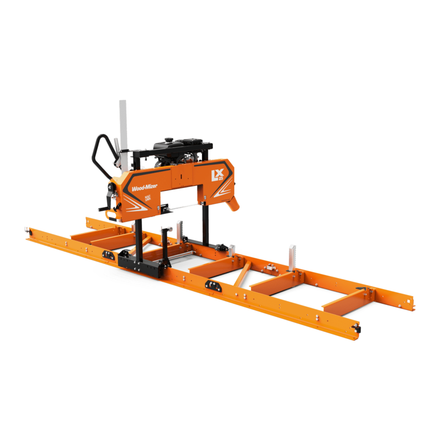
Introduction Major Components Major Components Major components of the basic LX25 sawmill are shown in MAJOR COMPONENTS. Other components are model-specific. These terms will be used throughout this manual. Scale Mast Sawhead Water (lube) Sawdust tank chute Up/down Log rest posts crank Blade guides Log clamp... -
Page 8: Specifications
Introduction Specifications Specifications TDL-LX25 LX25 4/8/21 Introduction... -
Page 9: Safety
OWNER/OPERATOR'S RESPONSIBILITY The procedures listed in this manual may not include all ANSI, OSHA, or locally required safety procedures. It is the owner/operator’s responsibility and not Wood-Mizer LLC to ensure all operators are properly trained and informed of all safety protocols. -
Page 10: Wear Safety Clothing (Personal Protection Equipment)
Safety Safety Instructions Read additional manufacturer’s manuals and observe their appli- cable safety instructions. Only persons who have read and understood the entire operator's manual should operate this equipment. This equipment is not intended for use by or around children. It is the owner/operator's responsibility to comply with all applicable federal, state, and local laws, rules, and regulations regarding... -
Page 11: Keep Work Area Clean
Safety Safety Instructions Keep Work Area Clean Clean sawdust from all guards, vents, control boxes, or any area WARNING! where sawdust may gather after every shift. Failure to do so may result in fire, causing death or serious injury Maintain a clean and clear path for all necessary movement around the equipment and lumber stacks. -
Page 12: Battery Safety
Safety Safety Instructions NOTICE Remove blades from equipment before cleaning them with fuel/flammable liquid. Dispose of fuel/flammable liquids per local ordinances. Battery Safety Batteries expel explosive gases; keep sparks, flames, burning cig- WARNING! arettes, or other ignition sources away at all times. Wear safety goggles and a face shield when working near batter- ies. -
Page 13: Sawmill Setup Safety
Safety Safety Instructions Ensure the battery is fully charged before transporting the sawmill. If the battery is not fully charged, excessive vibration could reduce the overall service life of the battery. EMERGENCY TREATMENT FOR CONTACT WITH BATTERY COMPONENTS (LEAD/SUL- FURIC ACID) per SDS (Safety Data Sheet): EYE CONTACT Sulfuric Acid and Lead: Flush eyes immediately with large amounts of water for at least 15 minutes while lifting lids. - Page 14 Safety Safety Instructions Keep all non-essential personnel out of the area while setting up the sawmill. LX25 4/8/21 Safety...
-
Page 15: Safety Decals
Safety Safety Decals Safety Decals 096317 Read Operator’s Manual CAUTION! Thoroughly read the manual before operating the machine. Observe all safety instruc- tions and rules when operating the mill. 096319 Disconnect Power Supply Before Opening (Electric version only) 096321 Blade Movement Direction 099220 Sawmill Covers Caution CAUTION! Close all guards and cov-... - Page 16 Safety Safety Decals 099222 Warning Projectile Hazard Wear safety goggles. 099221 Keep Away Danger CAUTION! Keep all persons a safe distance away from work area when operating the machine. 099221B 527864 Blade Tension Align the disc in the notch for proper blade tension.
- Page 17 Safety Safety Decals S12005g Use Ear Protection Wear ear protection at all times when operating the mill! Safety LX25 4/8/21...
-
Page 18: Setup
Setup Assemble the bed sections SECTION 3 SETUP Assemble the bed sections The tools needed are: Socket, 17mm Ratchet handle Ratchet extension bar (optional) Combination wrench, 17mm WARNING! Assemble the bed on firm, level ground. Failure to do so may cause the sawhead to tip, causing serious injury or death. - Page 19 Setup Assemble the bed sections 2. Assemble the remaining track rails and cross rail in a similar fashion. (See FIG. 3-2 .) Direction of cut TDLX2503-02 FIG. 3-2 3. Connect the bed sections using a connecting plate, a clamp, and hardware. Nut, M10-1.5 Flanged Clamp Nylon Lock...
- Page 20 Setup Assemble the bed sections NOTE: Be sure the track rails of each bed section are aligned before tightening the plate bolts. e. Fully tighten the plate bolts in the slotted holes on connecting plate. NOTE: Be sure the slotted holes on the connecting plate are con- nected to the same bed section on both sides of the bed frame.
-
Page 21: Level The Bed
Setup Assemble the bed sections 5. Attach the log rest brackets and posts.(See FIG. 3-5 .) Do not tighten until the bed is lev- eled. Posts Log Bracket TDLX25-04 FIG. 3-5 Level the bed The tools needed are: Shims 4 foot level or laser level ... - Page 22 Setup Assemble the bed sections one-piece section, make sure the seams of skids are offset from the seams of the bed frame. (See FIG. 3-6 .) Lag Bolt/washer Wooden Skid FIG. 3-6 2. Use a 4-foot level (or laser level) to level the bed in all dimensions. (See FIG. 3-7 .) Level FIG.
- Page 23 Setup Assemble the bed sections 4. When the bed is leveled, square up the log rest posts. Tighten the log rest bracket screws. (See FIG. 3-8 .)I Square Log Rest Post Log Rest Bracket FIG. 3-8 NOTE: Failure to square the log rest posts can result in poor cut quality. Recheck saw bed for level! Setup LX25 4/8/21...
-
Page 24: Install The Mast
Setup Install the mast Install the mast Prepare the mast carriages The sawhead carriages come mostly assembled from the factory. 1. Place 4 carriage bolts from the hardware kit through the inner side of the carriage. 2. Place washers and nuts loosely on the M10-1.5x70 carriage bolts. NOTE: Do not tighten them at this time. -
Page 25: Prepare Mast
Setup Install the mast 6. Remove the carriages from the rails for further installation with the mast. Prepare mast 1. Insert the mast cross member into the upright pieces, as shown in step 2. Set the bolts in place as shown in step NOTE: Do not tighten at this time. -
Page 26: Install The Sawhead
Setup Install the mast Install the sawhead 1. Lay the sawhead flat on a raised surface. 2. Slip the mast through the sawhead as shown in step NOTE: Ensure that the scale guide is on the same side as the up/down crank. - Page 27 Setup Install the mast NOTE: This prevents the sawhead from sliding up the mast while mounting it. (See FIG. 3-13 .)T Stop Pins FIG. 3-13 5. Raise the sawhead to the upright position. 6. Install the entire head and mast assembly on the bed rails. NOTE: Make sure that the main roller bearings are still riding smoothly on the rail.
- Page 28 Setup Install the mast 9. Move the carriage toward the foot of the bed and install the last segment of the catch rail, using M10-1.5x30 bolts. (See FIG. 3-14 .) Bolt, M10-1.5x30 Catch Rail Nut, M10-1.5 Flanged Nylon Lock FIG. 3-14 3-20 LX25 4/8/21 Setup...
-
Page 29: Install The Sweepers And Sawhead Stops
Setup Install the mast Install the sweepers and sawhead stops The tools needed are: Socket, 17mm Ratchet handle Screwdriver Ratchet extension bar (optional) Combination wrench, 17mm 1. Install the sawdust rail sweepers on the front sides of both carriages. Make sure that the sweepers contact the rails. -
Page 30: Install The Operator's Handle
Setup Install the mast 2. Attach the stop blocks (X100-1275) on the outside surface of the bed section at the head of the bed using M10-1.5x30 bolts. Tighten the nuts. (See FIG. 3-16 .) Nut, M10-1.5 Flanged Nylon Bolt, M10-1.5x30 Stop Block T10001-7 FIG. - Page 31 Setup Install the mast 1. Remove the operator’s handle from its shipping position by loosening the bolts enough to remove the handle and clipping the tie wrap holding on the throttle cable. 2. Invert the handle and replace it as shown. (See FIG. 3-17 .) Handle Bolt, M8 L Handle Nut, M8-1.25 Hex...
-
Page 32: Install The Clutch Cable
Setup Install the clutch cable Install the clutch cable The tools needed are: Socket, 10mm Combination wrench, 10mm Small adjustable wrench Ratchet handle The clutch cable was attached to the operator’s handle before shipping. The cable has an attaching eye and two adjustment nuts. - Page 33 Setup Install the clutch cable 1. Thread the clutch cable though the bracket on the operator’s handle by unthreading the upper adjustment nut and slipping the bare cable through the bracket. 2. Return the adjustment nut to the cable fitting. (See FIG. 3-19 .) Upper Adjustment Bracket 100B-007...
-
Page 34: Assemble The Up/Down Crank
Setup Install the clutch cable 6. Tighten the clutch cable in the bracket with a wrench. (See FIG. 3-20 .) Nut, M6 8 FE/ZN5 PN-85/M-82144 Nut, M6-1.0 Nylon Bolt, M6-1x70 HHB Lock Cable Eye FIG. 3-20 NOTE: The throttle should be adjusted after the LX25 is fully assem- bled and ready for use. - Page 35 Setup Install the clutch cable Combination wrench, 19mm Small adjustable wrench Hex drive, 3mm 1. Bolt on the crank handle. NOTE: Make sure that the lock washer is in place between the flat washer and bolt head as shown. (See FIG. 3-22 .) Nut, M12x1.75 Free Znc Crank Handle Lock washer...
- Page 36 Setup Install the clutch cable 2. Attach the lift cables and hangers from the hardware kit through the cross member on the mast upright. (See FIG. 3-23 .) Hanger Lift Cable 100B-014B FIG. 3-23 3. Back out the set screw from the crank shaft with the 3mm hex wrench and thread the lift cable through the hole in the crank shaft.
-
Page 37: Install Sawhead Cover Latch And Scale
Setup Install the clutch cable the saw head. Loctite or equivalent should be added to the set screw. 4. Return the set screw and tighten it. (See FIG. 3-24 .) 5. Repeat this procedure on the left side of the sawhead. Leave room for adjustment up or down. - Page 38 Setup Install the clutch cable 1. Place the latch hook into the top center of the saw head with the fasteners provided. (See FIG. 3-25 .) Latch Hook Bolt, M8-1.25x16 Washer, 8mm Split Lock, ZN FIG. 3-25 2. Slide the scale through the bracket on the mast with the scale facing the operator, as ...
- Page 39 Setup Install the clutch cable 6. Fasten the anti-vibration blocks with the provided hardware, as shown in step . The scale should slide freely through the blocks. (See FIG. 3-26 .) Washer, M6 Flat Class 4 Bolt, M6-1.0x30 Class 8 Mast Nut, M6-1.0 Nylon Lock Mast Bracket...
-
Page 40: Install The Lube Water Tank
Setup Install the clutch cable Install the lube water tank The tools needed are: Socket, 10mm Combination wrench, 10mm NOTE: Before installing the water tank, check for blade straightness. See "Blade straightness." In order to loosen the guide block, the water tank must be removed. -
Page 41: Install The Blade
Setup Install the Blade Socket, 10mm Combination wrench, 10mm Fasten the dust chute to the sawhead with the three M6-1 x 14 Class 8 bolts and nuts provided in the hardware kit. (See FIG. 3-28 .) Bolt, M6-1 x 14 Class 8 Washer, M6 Split Lock Washer, M6 Flat Class 4 100B-013... - Page 42 Setup Install the Blade 1. Watch the video on sawmill blades before removing the blade from the box. NOTE: Do not remove the blade from the shipping box at this time. 2. Go to: HOW TO COIL, UNCOIL, AND INVERT A BLADE https://www.youtube.com/watch?v=43TWwSgSOaQ 3.
- Page 43 Setup Install the Blade NOTE: When installing a blade, make sure the teeth are pointing t toward the dust chute. If necessary, invert the blade as shown in the video. 6. Position 1 1/4” wide blades on the wheels so the gullet is 1/8" (3.0 mm) out from the edge of the wheel.
-
Page 44: Sawmill Operation
Sawmill Operation SECTION 4 SAWMILL OPERATION WARNING! If a blade or drive belt breaks during operation, wait until all moving parts stop completely. Ensure ground is firm and level. Clear the area. Inspect the site for debris or uneven surfaces that may become a trip hazard. ... -
Page 45: Blade Tracking
Sawmill Operation Turn the blade tensioning nut until there is no gap between the back of tensioning plate and the housing. (SEE FIG. 4-2 .) No gap t10004-4B FIG. 4-2 Blade tracking When tensioned properly, check the tracking of the blade by spinning the wheel a few times by hand. - Page 46 Sawmill Operation The blade should track straight without moving in or out from the final setting, and the blade remains flush to 1/8" overhang to the rear edge of the wheel. (See FIG. 4-4 .) When the blade tracks straight, tighten the rear set nuts. Blade flush to 3mm(1/8") overhang here, both wheels...
-
Page 47: Blade Guides
Sawmill Operation Blade guides Check the ceramic blade guides for the proper setting. The two round ceramic guides should hover over and under the blade between 0.0075-0.010 inches (0.2 - 0.25mm) -- use the provided 0.0075" shim (p/n 035248) as a gauge. The adjustment bolts for the top and bottom guides face the foot of the sawmill. -
Page 48: Drive Belt Adjustment
Sawmill Operation Set both blade guide assemblies on each side of the blade in this manner. Adjustment bolts Set screw FIG. 4-6 Drive belt adjustment The idler pulley for the drive belt is adjustable by lengthening or shortening the clutch cable. -
Page 49: Changing Blades
Sawmill Operation Changing blades DANGER! Make sure that the engine is off before changing blades. Failure to do so will result in serious injury or death WARNING! Always wear gloves and eye pro- tection when handling bandsaw blades. Changing blades is safest when done by one person! Keep all other persons away from area when coiling, carrying, or changing a... -
Page 50: Blade Straightness
Sawmill Operation Blade straightness 1. Ensure that the blade is parallel to the bed. This can be accomplished by measuring the blade at both ends of the sawhead. 2. Measure the blade from a tooth pointing down on both sides of the sawhead. Pull the adjustable blade guide arm all the way out before measuring. -
Page 51: Blade Height Scale
Sawmill Operation Starting the Engine/Motor 6. Tighten the guide blocks. Blade height scale Adjustment nuts 100B-020 FIG. 4-11 1. Ensure that the blade is parallel to the bed. See "Blade straightness." 2. Measure the blade from a tooth pointing down to the mill bed surface. Raise or lower the sawhead as necessary to get an accurate measurement. - Page 52 Sawmill Operation Loading, Turning, and Clamping Logs 2. Lower the log clamp completely and move it toward the loading side of the sawmill frame. NOTICE Ensure the clamp is far enough down so the log does not hit it, resulting in machine damage. 3.
-
Page 53: Level A Log
Sawmill Operation Level a Log Level a Log Shim one end of the log (e.g. using an optional leveling wedge X100-1304_US) until the heart of the log measures the same distance from the bed rails at each end of the log. Leveling Wedge FIG. -
Page 54: Lift Operation
Sawmill Operation Lift Operation Lift Operation 1. Install a blade, if needed, and check for correct blade tension. 2. Use the crank handle to raise or lower the sawhead. TDLX25-06 Use crank handle to change sawhead height FIG. 4-14 One full turn of the crank handle moves the sawhead 1/2” (12.21 mm). If you rotate the crank handle by one tooth on the disc, the sawhead will be raised/lowered 1/32”... - Page 55 Sawmill Operation Engine Operation Warm engine: Disengage the tensioner handle (by moving it away from you). A warm engine usually does not require choke on. 5. Pull the engine starter cord slowly until you feel resistance, then pull the cord quickly to start the engine.
-
Page 56: Feed Operation
Sawmill Operation Feed Operation Feed Operation The feed operation is performed by pushing the sawhead manually at as steady a speed as manageable. Ensure the sawhead will not hit any bed components while in motion. 1. Feed the blade into the log at a slow speed to decrease the blade from flexing and dip- ping up or down. -
Page 57: Edging
Sawmill Operation Edging 13. Ensure the flat on the log is placed flat against side supports (if turned 90 degrees) or it is flat on bed rails. NOTE: If the log was turned 90 degrees and you are using the wedge to compensate for taper in the log, use the wedge again on the second side of the log until the heart is parallel with the bed. -
Page 58: Blade Height Scale
Sawmill Operation Blade Height Scale 4.10 Blade Height Scale TDLX25-08 FIG. 4-16 THE INCH SCALE The horizontal line on the blade height indicator shows how many inches the bottom of the blade is above the bed of the mill. If you know the height of your blade at each cut, you can determine the thickness of lumber you are sawing. - Page 59 Sawmill Operation Blade Height Scale THE QUARTER SCALE The quarter scale has four sets of marks. Each set represents a specific lumber thick- ness. Saw kerf and shrinkage allowance are included, but actual board thickness will vary slightly depending on blade thickness and tooth set. Standard Quarter Scale Scale Actual Board Thickness...
-
Page 60: Water Lube Operation
Sawmill Operation Water Lube Operation 4.11 Water Lube Operation The Water Lube System keeps the blade clean. Water flows from a 1-gallon (3.79 liter) bottle through a hose to the blade guide where the blade enters the log. A valve in the bottle cap controls the amount of water flow. -
Page 61: Transporting The Sawmill
Sawmill Operation Transporting the Sawmill 4.12 Transporting the Sawmill WARNING! Keep all persons out of the path of the sawhead while loading and unloading the sawmill. Failure to do so may result in serious injury or death. The assembled sawmill can be transported in an appropriately equipped pickup truck. 1. -
Page 62: Maintenance
Maintenance Continuous maintenance SECTION 5 MAINTENANCE WARNING! Shut down the sawmill and allow all moving parts to come to a complete stop before removing any guards and covers. Failure to do so may result in serious injury or death. Continuous maintenance Rails, rollers, and sweepers Proper maintenance of the sawmill carriage rollers and rails is critical for smooth operation of the sawmill. -
Page 63: General Maintenance
Maintenance Continuous maintenance Ensure that the sweepers are in contact with the rails, and that they are not clogged with sawdust. (See FIG. 5-1 .) Rails Sweeper Rollers 100B-026 FIG. 5-1 Clean rails to remove any sawdust and sap buildup after every use. Use a light-grade sandpaper or emery cloth to sand off any rust or other adhering particles from the rails. -
Page 64: Monthly (160 Hours Of Operation)
Maintenance Continuous maintenance Monthly (160 hours of operation) Grease the lift cables on both sides of the sawhead with white lithium grease. (See FIG. 5-2 .) Grease 100B-025 FIG. 5-2 Engine maintenance Refer to the manufacturer’s engine manuals for maintenance. 5-56 LX25 4/8/21 Maintenance... -
Page 65: Sawhead Parts
Sawhead Parts Sliding Blade Guide Arm Assembly SECTION 6 SAWHEAD PARTS Sliding Blade Guide Arm Assembly DESCRIPTION (♦ Indicates Parts Available in Assemblies Only) PART # QTY. ASSY, SLIDING GUIDE X100-963 Sleeve, Vinly Guard 086875 Lever, Blade Guide X100-336 Grommet, Rubber 3/8 Dia 025248 Nut, M8-1.25 Hex Nylock F05010-132... -
Page 66: Blade Guide Assembly
Sawhead Parts Blade Guide Assembly Blade Guide Assembly 100b-027 6-58 LX25 4/8/21 Sawhead Parts... - Page 67 Sawhead Parts Blade Guide Assembly DESCRIPTION (♦ Indicates Parts Available in Assemblies Only) PART # QTY. ASSY, BLADE GUIDE IDLE SIDE X100-964 Nut, M8-1.25 Hex Nylock F05010-132 Washer, M8 Flat F05026-4 Ceramic, 7/8 Dia x .825 Long X200-433 Block, Blade Guide T100 X100-977 Washer, M6 Split Lock F05026-2...
-
Page 68: Clutch Assembly
Sawhead Parts Clutch Assembly Clutch Assembly TDLX2501 DESCRIPTION (♦ Indicates Parts Available in Assemblies Only) PART # QTY. ASSY, CLUTCH T100 X100-960 Spacer, Clutch X200-1165 Bushing, Clutch Idler X100-390 Pulley, Idler 5/8x2 3/4 X200-906 Arm, Clutch X100-340 Nut, M10-1.50 Hex Nyl Lock F05004-270 Nut, M5-.8 Class 8 Hex Nylock F05027-3... -
Page 69: Scale And Sawdust Chute
Scale and Sawdust Chute 10 11 12 100b-028 DESCRIPTION (♦ Indicates Parts Available in Assemblies Only) PART # QTY. ASSY, SCALE LX25 130301 Decal, Wood-Mizer Inch Scale 123059 Bracket, Scale X100-348 Bolt, M6-1.0x30 Class8 HH F05020-8 Washer, M6 Flat Class 4 F05026-1... -
Page 70: Cover Hold-Up Latch
Sawhead Parts Cover Hold-up Latch Cover Hold-up Latch 10 11 100B-029 DESCRIPTION (♦ Indicates Parts Available in Assemblies Only) PART # QTY. ASSY, COVER LATCH X100-981 Washer, M8 Split Lock F05011-45 Bolt, M8x1.25x16mm HH F05004-47 Hook, Cover X100-1020 Bolt, M6-1 x 20 Class 8 HH F05020-6 Nut, M6-1.0 Free Nut Zinc F81031-1... -
Page 71: Water Tank
Sawhead Parts Water Tank Water Tank DESCRIPTION (♦ Indicates Parts Available in Assemblies Only) PART # QTY. ASSY, WATER TANK X100-970 Tank, Water, 4 qt X100-904 Washer, M6 Flat Class 4 F05026-1 Screw, M6-1x12 HHC FT GR8-8 Din 933 F05005-99 Nut, M6-1.0 Nylon Lock F05010-200 Valve, 1/4 Water Shutoff... -
Page 72: Up/Down Slides
Sawhead Parts Up/down Slides Up/down Slides DESCRIPTION (♦ Indicates Parts Available in Assemblies Only) PART # QTY. ASSY, UP/DOWN SLIDE X100-962 Screw, M8-1.25x30 HHC F05021-11 Washer, M8 Flat F05026-4 Block, Vertical Slide Guide X100-327 Nut, M8-1.25 Hex Nylock F05010-132 Nut, M8-1.25 Free Zinc Plate F05010-162 Bolt, M8x50 8.8 HH FT Zinc F81002-19... -
Page 73: Winch
Sawhead Parts Winch Winch 12 13 14 7 8 9 10 11 17 18 19 20 21 22 24 25 DESCRIPTION (♦ Indicates Parts Available in Assemblies Only) PART # QTY. ASSY, WINCH T100 x100-1051 Cable, Lift Paddle 27.25" X100-1056 Collar, 3/4 ID Zinc P04146 Bushing, Bronze 3/4x7/8... - Page 74 Sawhead Parts Winch DESCRIPTION (♦ Indicates Parts Available in Assemblies Only) PART # QTY. Pawl, Winch X100-385 Spring, 5/16ODx1 9/32x.023 Wire Ext X200-992 Nut, M6-1.0 Nylon Lock F05010-200 Nut, M10-1.50 Hex Nyl Lock F05004-270 Nut, M12-1.75 Jam F05027-19 Washer, 12mm Split Lock f05011-123 Nut, M12x1.75 Free Zinc f05010-212...
-
Page 75: Throttle Lever
Sawhead Parts Throttle Lever Throttle Lever To clutch To throttle lever To engine throttle Clutch view Sawhead Parts LX25 4/8/21 6-67... - Page 76 Sawhead Parts Throttle Lever DESCRIPTION (♦ Indicates Parts Available in Assemblies Only) PART # QTY. ASSY, THROTTLE LEVER X100-969 Assy, "L" Handle X100-975 Bolt, M8 L Handle X100-386 Washer, M8 Flat F05026-4 Nut, M8-1.25 Hex Nylock F05010-132 Nut, M6-1.0 Nylon Lock F05010-200 Washer, M6 Flat Class 4 F05026-1...
-
Page 77: Blade Tension Assembly
Sawhead Parts Blade Tension Assembly 6.10 Blade Tension Assembly 9 10 DESCRIPTION (♦ Indicates Parts Available in Assemblies Only) PART # QTY. ASSY, BLADE TENSION X100-979 Bolt, M10-1.50x50mm HHFT 8.8 F05004-269 Nut, M10-1.5 Hex F05010-85 Pin, 3/8x 2 5/8 Clevis, Zinc F05012-138 Pin, 3/32x3/4 Cotter F05012-9... -
Page 78: Band Wheel Assembly
Sawhead Parts Band Wheel Assembly 6.11 Band Wheel Assembly 100B-35 DESCRIPTION (♦ Indicates Parts Available in Assemblies Only) PART # QTY. ASSY, BANDWHEEL SHAFT X100-961 Spindle, Blade Wheel X100-301 Ring, 2 7/16 IR N 5002-244 Beveled Snap F04254-21 Sheave, Bandwheel, 15 3/8 OD X100-303 Bearing, 6305 62 OD x 25 ID x 17 W P08066... -
Page 79: Sawhead Cover
Sawhead Parts Sawhead Cover 6.12 Sawhead Cover 14 15 16 10 11 12 100B-030 Sawhead Parts LX25 4/8/21 6-71... - Page 80 Sawhead Parts Sawhead Cover DESCRIPTION (♦ Indicates Parts Available in Assemblies Only) PART # QTY. ASSY, COVER T100 X100-967 Screw, M6-1x12 HHC FT GR8-8 Din 933 F05005-99 Washer, M6 Flat Class 4 F05026-1 Bracket, Latch X200-913 Nut, M4-.7 Class 8 Nylock F05027-8 Weldment, Cover X100-922...
-
Page 81: Decals
Sawhead Parts Decals 6.13 Decals TDLX25-01 TDLX25-02 Sawhead Parts LX25 4/8/21 6-73... - Page 82 Decal, Close Guards Before Operating 099220 Decal, Blade Movement Direction 096321 Decal, Wood-Mizer Website Logo 003325 Decal, Saw Dust Protection-Pictogram 099222 Decal, Wood-Mizer Quality & Information 079278 Decal, Eye Warning S12004G Decal, Wear Safety Boots 501465 Decal, Ear Warning S14005G...
-
Page 83: Engine Parts
Engine Parts Kohler 9hp Gas Engine SECTION 7 ENGINE PARTS Kohler 9hp Gas Engine 9 10 55006 DESCRIPTION (♦ Indicates Parts Available in Assemblies Only) PART # QTY. ENGINE ASSY, 9HP KOHLER Cable, Throttle 20x28 SpringxCable X100-1092 Plate, Kohler Throttle Cable Mounting X200-1203 Throttle Fitting, Swivel 048904... -
Page 84: Kohler 7Hp Gas Engine
Engine Parts Kohler 7hp Gas Engine Kohler 7hp Gas Engine See Note 100105 DESCRIPTION (♦ Indicates Parts Available in Assemblies Only) PART # QTY. ENGINE KIT, G7 KOHLER X100-1082 Cable, Throttle 20x26 SpringxCable X100-1092 F05004-85 Screw, 8-32x3/8 SHC Plate, 7hp Kohler Throttle Mounting X100-1085 Bolt, M8-1.25x20 Class 8 HH F05021-2... -
Page 85: Bed And Carriage Assembly
Bed and Carriage Assembly SECTION 8 BED AND CARRIAGE ASSEMBLY TDLX2503-01 DESCRIPTION (♦ Indicates Parts Available in Assemblies Only) PART # QTY. BED ASSY, LX25 128353 Pin, 3/8x2 1/4 Sq Wire Lock 014151 Plate, T100 Drive/Idle Side Rail X100-929-W Bracket, Center Bed Rail 123031-W Bolt, M10-1.5x85 Class 8 HH F81003-125... -
Page 86: Log Clamp
Bed and Carriage Assembly Log Clamp Log Clamp TDLX2502-01 DESCRIPTION (♦ Indicates Parts Available in Assemblies Only) PART # QTY. CLAMP ASSY, LOG METRIC X200-1082 Block, Clamp Point 075295 Weldment, Clamp Post Tube 071343 Assy, Clamp Screw 071350 Bolt, M10-1.5x140 HH FT F05022-21 Washer, 3/8 Flat SAE F05011-3... -
Page 87: Carriage
Bed and Carriage Assembly Carriage Carriage 10 11 12 13 x100102-2 Bed and Carriage Assembly LX25 4/8/21 8-79... - Page 88 Bed and Carriage Assembly Carriage DESCRIPTION (♦ Indicates Parts Available in Assemblies Only) PART # QTY. ASSY, CARRIAGE x100-1043 Tube, Carriage Horizontal X100-1049 Nut, M10-1.50 Hex Nyl Lock F05004-270 Bolt, M10-1.5x75 HH Class 8.8 F05022-15 Weldment, Carriage Right Side Post X100-1045 Weldment, Carriage Left Side Post X100-1044...
-
Page 89: Log Rest
Bed and Carriage Assembly Log Rest Log Rest DESCRIPTION (♦ Indicates Parts Available in Assemblies Only) PART # QTY. Post, Log Rest X200-1026 Bolt, M10-1.5x30 Class 8 Hex Head F05022-3 Washer, M10 Flat SAE F05011-134 Bracket, Log Rest X200-1027 Nut, M10-1.5 Flanged Nylon Lock F05027-47 Post, Log Rest, Short X200-1045... -
Page 90: Optional Log Ramps
Bed and Carriage Assembly Optional Log Ramps Optional Log Ramps 123096 DESCRIPTION (♦ Indicates Parts Available in Assemblies Only) PART # QTY. ASSY, 2 LOG RAMPS LX55/25 123252 Assy, Log Ramp LX55/25 123096 Bracket, Log Stop LX55/25 123098 Washer, M10 Flat SAE F05011-134 Nut, M10-1.50 Hex Nyl Lock F05004-270... -
Page 91: Optional Adjustable Feet
Bed and Carriage Assembly Optional Log Ramps Optional Adjustable Feet 55008 For full bed DESCRIPTION (♦ Indicates Parts Available in Assemblies Only) PART # QTY. ASSY, SAWMILL BED FEET (QTY 12) 128127 Kit, Sawmill Feet Fastener 130829 Washer, M20 Flat Zinc F05026-16 Nut, M20-2.5 Free F05027-26...
Need help?
Do you have a question about the LX25G9 and is the answer not in the manual?
Questions and answers