Wood-mizer LT20 Series User Manual
Hide thumbs
Also See for LT20 Series:
- Safety, setup, operation & maintenance manual (134 pages) ,
- Safety, setup, operation & maintenance manual (106 pages) ,
- Safety, setup, operation & maintenance manual (137 pages)
Table of Contents
Advertisement
Advertisement
Table of Contents
Troubleshooting

Related Manuals for Wood-mizer LT20 Series


Summary of Contents for Wood-mizer LT20 Series
- Page 3 ® Wood-Mizer Sawmill Safety, Setup, Operation & Maintenance Manual LT20 Series DH rev. D2.03 Safety is our #1 concern! Read and understand all safety information and instructions before operating, setting up or maintaining this machine. April 2003 Form #629...
- Page 4 +48-63-2626000. From the continental U.S., call our toll-free Parts hotline at 1-800-448-7881. Please have the vehicle identification number and your customer num- ber ready when you call. Wood-Mizer will accept these methods of payment: • Visa, Mastercard, or Select Purchase •...
- Page 5 Sawmill and Customer Identification Each Wood-Mizer sawmill has a 17-digit Vehicle Identification Number (VIN). See the fig- ure below for VIN locations. See the chart for VIN description. V.I.N. LOCATIONS. F9 017 F9 .01 V.I.N. DESCRIPTION...
- Page 6 Each sawmill is also identified with a model number which includes the base model and the engine/motor configuration. See the figure for a description of the model number. LT20 Engine/Motor Basic Sawmill I.D. Configuration MODEL NUMBER DESCRIPTION. When you pick up your mill, you will receive a customer number. Both the VIN and your customer number expedite our service to you.
-
Page 7: Table Of Contents
1.15 LT20 Series A/DH5 Hydraulic Schematic .............. 1-19 1.16 LT20 Series A/DH7 Hydraulic Schematic .............. 1-20 1.17 LT20 Series A/DH - Hydraulic Components ............1-21 1.18 LT20 Series A/DH - Hydraulic Hoses..............1-22 SECTION 2 SETUP & OPERATION Stationary Sawmill Setup ..................2-1 Portable Sawmill Setup ..................... - Page 8 Table of Contents Section-Page SECTION 3 MAINTENANCE Wear Life........................3-1 Blade Guides ......................3-2 Sawdust Removal ...................... 3-2 Carriage Track, Wiper & Scrapers ................3-3 Vertical Mast Rails ....................3-4 Miscellaneous ......................3-4 Blade Tensioner......................3-5 Blade Wheel Belts ..................... 3-5 Brake Pads Adjustment ( Gas / Diesel Sawmills Only ) ...........
-
Page 9: Section 1 Safety & General Information
It is always the owner's responsibility to comply with all applicable federal, state and local laws, rules and regulations regarding the ownership, operation and towing of your Wood-Mizer sawmill. All Wood-Mizer mill owners are encouraged to become thoroughly familiar with these applicable laws and comply with them fully while using or towing the mill. -
Page 10: Safety & General Information Blade Handling
Safety & General Information Blade Handling Blade Handling DANGER! Always disengage the blade and shut off the sawmill engine before changing the blade. Failure to do so will result in serious injury. WARNING! Always wear gloves and eye protection when handling bandsaw blades. -
Page 11: Sawmill Setup
Safety & General Information Sawmill Setup Sawmill Setup WARNING! Chock the trailer wheels to prevent movement before unhitching it from the towing vehicle. Failure to do so may result in serious injury or death. WARNING! Failure to put front outrigger down before moving cutting head from the rest position may result in serious injury. -
Page 12: Sawmill Operation
Safety & General Information Sawmill Operation Sawmill Operation DANGER! Make sure all guards and covers are in place and secured before operating or towing the sawmill. Failure to do so may result in serious injury. Be sure the blade housing and pulley covers are in place and secure. - Page 13 Safety & General Information Sawmill Operation WARNING! Always make sure log is clamped securely before sawing. Failure to do so may result in serious injury or death. WARNING! Use ONLY water with the water lube accessory. Never use flammable fuels or liquids. If these types of liquids are necessary to clean the blade, remove it and clean with a rag.
-
Page 14: Sawmill Maintenance
Safety & General Information Sawmill Maintenance Sawmill Maintenance WARNING! Always secure the cutting head with a chain or a brace before adjusting the up/down chain. The cutting head may fall, causing severe injury or death. WARNING! Always secure the cutting head with a chain or a brace before adjusting the mast pads. - Page 15 Safety & General Information Sawmill Maintenance See Table 1-1. Pictogram decals used to warn and inform the user about danger in the LT20. TABLE 1-1 Decal View W-M No. Description 096317 CAUTION! Read thoroughly the manual before operating the machine. Observe all safety instructions and rules when operating the sawmill.
- Page 16 Safety & General Information Sawmill Maintenance TABLE 1-1 099221 CAUTION! Keep all persons a safe distance away from work area when operating the machine. 099221 098176 CAUTION! Keep away from debarker blade! 098176 096316 CAUTION! Do not open or close the electric box when the switch is not in the “0”...
- Page 17 Safety & General Information Sawmill Maintenance TABLE 1-1 096319 CAUTION! Disconnect power supply before opening the box. 099222 CAUTION! Sawdust outlet. Protect eyes! 099542 CAUTION! Trailer. 099542 086099 CAUTION! Hot elements, keep your distance! 086099 Safety & General Information 25doc061008...
- Page 18 Safety & General Information Sawmill Maintenance TABLE 1-1 096321 Blade movement direction S12004G CAUTION! Always wear safety goggles when operating the sawmill! S12005G CAUTION! Always wear protective ear muffs when operating the sawmill! P11789 Aligning the blade on the wheels 1-10 25doc061008 Safety &...
- Page 19 Safety & General Information Sawmill Maintenance TABLE 1-1 092597 Setting the blade tension indicator 092597 P85070 CE safety certification 099401 Russian safety certification 099401 S20097 Motor rotation direction S20097 Safety & General Information 25doc061008 1-11...
-
Page 20: Belt Sizes
Safety & General Information Belt Sizes Belt Sizes See Table 1-2. Belt sizes for the LT20 Series sawmill are shown. Description Belt Size Wood-Mizer Part # BX81 014819 Motor Drive Belt E11 & E15 Engine Drive Belt D22, G25 BX83,5... -
Page 21: Cutting Capacity
Safety & General Information Cutting Capacity Cutting Capacity See Table 1-4. The log size capacities of the LT20 series sawmill are listed below. Max. Max. Diameter Length LT20 S 71 cm 5.1 m (16' 8") LT20 M 71 cm 6.4 m (21') -
Page 22: Engine/Motor Specifications
Safety & General Information Engine/Motor Specifications Engine/Motor Specifications See Table 1-6. The power options available for the LT20 Series sawmill are listed below. Engine/Motor Type Manufacturer Model No. Power Other Specifications 11HP Electric Tamel SA, Sg 132M-2PE 7.5 kW 14.7 A, 2950 RPM... -
Page 23: Overall Dimensions
Safety & General Information Overall Dimensions Overall Dimensions See Table 1-8. The overall dimensions of the LT20 series sawmill are listed below. Model Width Weight Weight Length Width Height Operating Position w/Trailer (Loading Arms Raised) LT20SG15 6.7 m 3.5 m... -
Page 24: Sawdust Extractor Specifications
Safety & General Information Sawdust Extractor Specifications 1.11 Sawdust Extractor Specifications See Table 1-11. The dust extractor specifications are given below. Maximum Capacity 1200 m Collector Inlet Diameters (in 150 mm front of fan) Motor Power 1.5 kW Number of Sacks for Waste 1 szt. -
Page 25: Components
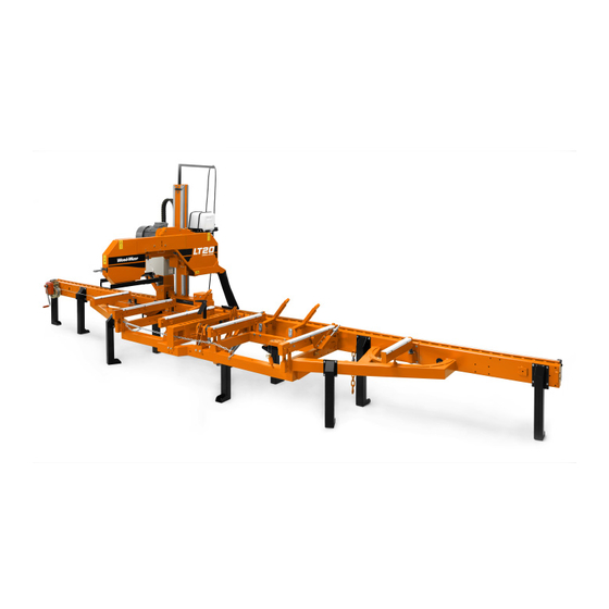
Safety & General Information Components 1.13 Components See Figure 1-1. The major components of the Wood-Mizer LT20 Series are shown below. FIG. 1-1 Safety & General Information 25doc061008 1-17... -
Page 26: Lt20 Series Dh3 Hydraulic Schematic
Safety & General Information LT20 Series DH3 Hydraulic Schematic 1.14 LT20 Series DH3 Hydraulic Schematic RELIEF VALVE SETTING 2000 PSI LOADER CLAMP CLAMP TOEBOARD TOEBOARD TURNER IN/OUT UP/DOWN REAR FRONT RELIEF VALVE SETTING 2250 PSI HD0138 FIG. 1-2 HYDRAULIC SCHEMATIC. -
Page 27: Lt20 Series A/Dh5 Hydraulic Schematic
Safety & General Information LT20 Series A/DH5 Hydraulic Schematic 1.15 LT20 Series A/DH5 Hydraulic Schematic RYS. 1-4 Safety & General Information 25doc061008 1-19... -
Page 28: Lt20 Series A/Dh7 Hydraulic Schematic
Safety & General Information LT20 Series A/DH7 Hydraulic Schematic 1.16 LT20 Series A/DH7 Hydraulic Schematic RYS. 1-5 1-20 25doc061008 Safety & General Information... -
Page 29: Lt20 Series A/Dh - Hydraulic Components
Safety & General Information LT20 Series A/DH - Hydraulic Components 1.17 LT20 Series A/DH - Hydraulic Components Mfg. Part No. Wood-Mizer Description Part # CJ-S96-16-70/32/178 088589 Hyd. Cylinder, 70mm Bore X 178mm Stroke CJ-S169-16-40/22/254 088590 Hyd. Cylinder, 40mm Bore X 254mm... -
Page 30: Lt20 Series A/Dh - Hydraulic Hoses
Safety & General Information LT20 Series A/DH - Hydraulic Hoses 1.18 LT20 Series A/DH - Hydraulic Hoses Color LENGTH Application Wood-Mizer Code "A" Part No. None 18" 1/4” Hydraulic Pump To Valve 015704 Plain 0.55m 3/8” Log Turner Cylinder Base 014796 (22") - Page 31 Safety & General Information LT20 Series A/DH - Hydraulic Hoses Blue 4.34m 3/8” Loading Arm Cylinder Top (LT40S) 087795 (171") 4.9m 3/8” Loading Arm Cylinder Top (LT40M) 087781 (193") 4.34m 3/8” Loading Arm Cylinder Bottom (LT40S) 087795 (171") 4.9m 3/8” Loading Arm Cylinder Bottom (LT40M) 087781 (193")
- Page 32 Safety & General Information LT20 Series A/DH - Hydraulic Hoses White 1,20 1/4" FIRST/SECOND CLAMP, IN/OUT CYLINDER TOP (AH7) 095217 TABLE 1-14 1-24 25doc061008 Safety & General Information...
-
Page 33: Setup & Operation
SETUP & OPERATION Stationary Sawmill Setup SECTION 2 SETUP & OPERATION Stationary Sawmill Setup Set up the mill on firm footing and level by eye. Fasten the mill to the floor to prevent any creep after prolonged use. A cement pad with 5/8” (16 mm) diameter anchor bolts is rec- ommended. - Page 34 SETUP & OPERATION Stationary Sawmill Setup 3830 2040 2790 LT20 S Stationary Metric Dimensions* 1790 2620 1935 20_108B 2590 2820 LT20 M Stationary Metric Dimensions* *All dimensions in millimetres FIG. 2-2 1. Unhook the carriage safety chain, located at the bottom of the vertical mast. 2.
- Page 35 SETUP & OPERATION Stationary Sawmill Setup See Figure 2-3. Pivot End Rail Side Support Bed Rail Stop Block SM0130 FIG. 2-3 SETUP & OPERATION 25doc061008...
-
Page 36: Portable Sawmill Setup
SETUP & OPERATION Portable Sawmill Setup Portable Sawmill Setup WARNING! Do not set up the mill on ground with more than incline. If setup on an incline is necessary, put blocks under one side of the mill or dig out areas for outrigger legs to keep mill level. - Page 37 SETUP & OPERATION Portable Sawmill Setup See Figure 2-4. Adjustment Bolt Locking Pin Travel Lock Pin Outrigger Leg FIG. 2-4. OUTRIGGER ADJUSTMENT. CAUTION! If setup sawmill on a boggy terrain (such as deep mud or sand) place the board or metal plate under each outrigger leg to prevent it from sinking.
- Page 38 SETUP & OPERATION Portable Sawmill Setup See Figure 2-5. Distance Block Stop Bolt FIG. 2-5 WARNING! Put front outrigger down before moving cutting head from the rest position. Failure to do so may result in serious injury. CAUTION! To prevent fender damage, remove fenders before operating sawmill or loading logs.
- Page 39 SETUP & OPERATION Portable Sawmill Setup See Figure 2-6. Pivot End Rail Side Support Bed Rail Stop Block SM0130 FIG. 2-6 SETUP & OPERATION 25doc061008...
-
Page 40: Middle Track Cover
SETUP & OPERATION Middle Track Cover Middle Track Cover Before operating the sawmill do as follows: 1. Clean the upper and lower rails to remove any sawdust and rust preventives. 2. Unbolt and remove the middle track cover from its storage position. 3. -
Page 41: Replacing The Blade
SETUP & OPERATION Replacing The Blade Replacing The Blade DANGER! Always shut off the sawmill motor before chang- ing the blade. Failure to do so may result in serious injury. WARNING! Always wear gloves and eye protection when- ever handling bandsaw blades. Changing blades is safest when done by one person! Keep all other persons away from work area when changing blades. -
Page 42: Tensioning The Blade
SETUP & OPERATION Tensioning The Blade Tensioning The Blade See Figure 2-8. Turn the blade tension handle clockwise to compress the rubber spring and tension the blade. Check the blade tension occasionally when adjusting the cant con- trol or while cutting. As the blade and belts heat up and stretch, the blade tension will change. -
Page 43: Tracking The Blade
SETUP & OPERATION Tracking The Blade Tracking The Blade 1. Open the blade housing cover. 2. Turn the key switch to the ”H” position. 3. Manually spin one of the blade wheels until the blade positions itself on the blade wheels. 4. - Page 44 SETUP & OPERATION Tracking The Blade housing cover is in place and secured. DANGER! After aligning the blade on the wheels, always check the blade guide spacing and location. (See Section 5 for more information.) See Section 1.11 2-12 25doc061008 SETUP &...
-
Page 45: Hydraulic Control Operation
SETUP & OPERATION Hydraulic Control Operation Hydraulic Control Operation The hydraulic control levers become operational when the main switch located on the starter box is in the “1” position the contacts at the bottom of the carriage touch the power strip on the frame tube. - Page 46 SETUP & OPERATION Hydraulic Control Operation See Figure 2-10. A/DH3 Hydraulic units have six control levers to load, clamp, turn and level logs. A/DH5 and A/DH7 hydraulic units have four additional levers for controlling the Pull-Down clamps. In sawmills equipped with A/DH5 hydraulic system, individual Pull-Down clamps are controlled with separate levers.
- Page 47 SETUP & OPERATION Hydraulic Control Operation See Figure 2-11. A/DH5 Hydraulic System. 094795 Front Rear Clamp Clamp Up/Down Up/Down Front Rear Clamp AC0052 Clamp In/Out In/Out RYS. 2-11 See Figure 2-12. A/DH7 Hydraulic System. FRONT MIDDLE REAR 094970 Clamp Clamp I/II/III In/Out Up/Down...
- Page 48 SETUP & OPERATION Hydraulic Control Operation DANGER! Keep all persons out of the path of moving equipment and logs when operating sawmill or loading and turning logs. Failure to do so will result in serious injury. CAUTION! Always make sure the engine is running before operating the hydraulic controls.
- Page 49 SETUP & OPERATION Hydraulic Control Operation 1. Move the clamp out and down so it will not get in the way of logs being loaded onto the bed. Lower the clamp in/out lever to move the clamp out toward the loading side of the saw- mill.
-
Page 50: Loading, Turning, And Clamping Logs
SETUP & OPERATION Loading, Turning, And Clamping Logs Loading, Turning, And Clamping Logs CAUTION! Be sure the pivot rails, turning arm, clamp, and toe boards are below bed level before loading a log onto the bed. Failure to do so may result in machine damage or cause misalignment. - Page 51 SETUP & OPERATION Loading, Turning, And Clamping Logs To Turn Logs 1. Raise the turner lever to engage the log turner arm. Let the arm rise until it touches the log and starts to turn it. 2. Spin the log against the side supports until it is turned the way you want it for the first cut. If you want to turn the log more, do the following steps.
- Page 52 SETUP & OPERATION Loading, Turning, And Clamping Logs To Clamp Logs 1. Raise the clamp in/out lever and clamp the log against the side supports. 2. Lower the turner lever until the turner arm falls below the bed. 3. When the turner arm is lowered all the way, the side supports will begin to lower. Back the clamp off slightly, and let the side supports come down until they are positioned below the level of your first few cuts.
-
Page 53: Up/Down Operation
SETUP & OPERATION Up/Down Operation Up/Down Operation 1. Install a blade and check for correct blade tension. (See Section 2.4). 2. Set the cutting head to the desired height. (The blade height scale shows the height of the blade above the bed rails.) See Figure 2-13. -
Page 54: Blade Guide Arm Operation
SETUP & OPERATION Blade Guide Arm Operation 2.10 Blade Guide Arm Operation 1. Look down the length of the log to see its maximum width. The outer blade guide should be adjusted to clear the widest section of the log by less than about 25 mm. 2. -
Page 55: Power Feed Operation
SETUP & OPERATION Power Feed Operation 2.11 Power Feed Operation See Figure 2-15. The power feed system moves the carriage forward and backward by using two switches on the control panel. Carriage Forward Feed Rate Adjustment Carriage Reverse 20_121B FIG. 2-15 Carriage Feed Rate The carriage feed rate switch controls the speed at which the carriage travels forward. - Page 56 SETUP & OPERATION Power Feed Operation NOTE: Always disengage the blade before returning the carriage and raise the carriage slightly to make sure the blade clears the log. The middle position (shown in the figure above) is the neutral position. The power feed switch is designed to return to the neutral position when released.
- Page 57 SETUP & OPERATION Power Feed Operation heel of the blade is still on the log. Then bring the carriage back without adjusting the blade up. This lets you keep the blade at the current height setting so you can make the next blade height adjustment more quickly.
-
Page 58: Cutting The Log
Cutting The Log 2.12 Cutting The Log The following steps guide you through normal operation of the Wood-Mizer sawmill. 1. Once the log is placed where you want it and clamped firmly, position the blade close to the end of the log. -
Page 59: Edging
1” (25.4 mm) thick boards, lower the carriage 1 1/16 - 1 1/8” (27-28.6 mm) for each board. 2.13 Edging The following steps guide you through edging boards on the Wood-Mizer sawmill. 1. Raise the side supports to ˝ the height of the flitches, or the boards that need to be edged. -
Page 60: Blade Height Scale
SETUP & OPERATION Blade Height Scale 2.14 Blade Height Scale See Figure 2-16. The blade height scale is attached to the cutting head frame. It includes: a blade height indicator an inch scale. Blade Height Quarter Indicator Scale Inch Scale FIG. - Page 61 SETUP & OPERATION Blade Height Scale The Quarter Scale See Table 2-1. Two quarter scales are provided with four sets of marks. Each set repre- sents a specific lumber thickness. Saw kerf and shrinkage allowance are included, but actual board thickness will vary slightly depending on blade thickness and tooth set. To choose which scale to use, determine what finished thickness you want to end up with.
-
Page 62: Water Lube Operation
SETUP & OPERATION Water Lube Operation 2.15 Water Lube Operation See Figure 2-17. The Water Lube System keeps the blade clean. Water flows from a 5-gallon (18.9 liter) bottle through a hose to the blade guide where the blade enters the log. -
Page 63: Preparing The Sawmill For Towing
Preparing The Sawmill For Towing 2.16 Preparing The Sawmill For Towing The Wood-Mizer trailer package makes transporting your sawmill easy and convenient. To get your sawmill ready for towing, follow these instructions. 1. Move the cutting head to the front end of the sawmill. Raise the rear outriggers. - Page 64 SETUP & OPERATION Preparing The Sawmill For Towing adjusted to secure the carriage on the track rail. Failure to properly adjust the stop bolt can cause cutting head dam- age, especially during mill transportation. 7. Hook the carriage safety chain attached to the main bed tube, behind the trailer to the bracket located near the lower track roller.
- Page 65 SETUP & OPERATION Preparing The Sawmill For Towing CAUTION! Check to be sure that the carriage safety chain is secured before towing the sawmill. Failure to properly secure the cutting head can result in severe machine dam- age. Be sure the blade housing cover is in place and secured.
-
Page 66: Maintenance
MAINTENANCE Wear Life SECTION 3 MAINTENANCE This section lists the maintenance procedures that need to be performed. The Short Interval Maintenance Schedule lists procedures that need to be performed every 4, 8 or 24 hours. The Maintenance Log lists procedures that need to be performed every 50, 100, 200,or 1000 hours. -
Page 67: Blade Guides
MAINTENANCE Blade Guides Blade Guides 1. Check the rollers for performance and wear every blade change. Make sure the rollers are clean and spinning freely. If not, rebuild them. Replace any rollers which have worn smooth or have become cone shaped. See The LT20 Parts manual for blade guide rebuild kits and complete roller assemblies. -
Page 68: Carriage Track, Wiper & Scrapers
MAINTENANCE Carriage Track, Wiper & Scrapers Carriage Track, Wiper & Scrapers See Figure 3-2. 1. Clean the upper and lower track rails to remove any sawdust and sap buildup every eight hours of operation. Lubricate the lower track rail by wiping it with Dexron III ATF. 2. -
Page 69: Vertical Mast Rails
MAINTENANCE Vertical Mast Rails Vertical Mast Rails Lubricate the vertical mast rails with WD40, clean and wipe them dry every 50 hours of operation. CAUTION! Never use grease on the mast rails as it will col- lect sawdust. Miscellaneous 1. Apply a thin film of a lithium grease to the blade guide arm to help prevent it from rusting. 2. -
Page 70: Blade Tensioner
MAINTENANCE Blade Tensioner Blade Tensioner Grease the tensioner handle screw with a lithium grease every fifty hours of operation, but at least once a week. See Figure 3-3. Tensioner Handle Screw 20_006a FIG. 3-3 Blade Wheel Belts 1. Check the blade wheel belts for wear every 50 hours of operation. Replace as needed. 2. -
Page 71: Brake Pads Adjustment ( Gas / Diesel Sawmills Only )
MAINTENANCE Brake Pads Adjustment ( Gas / Diesel Sawmills Only ) Brake Pads Adjustment ( Gas / Diesel Sawmills Only ) Check the brake pads for wear every 200 hours of operation. Replace if damaged or worn. Adjust the brake pads if the blade does not stop quickly, unusual sounds occur when the brake is applied, or a sudden change is noticed in the clutch/brake lever position when the clutch is disengaged. -
Page 72: Drive Belt Adjustment
MAINTENANCE Drive Belt Adjustment 3.10 Drive Belt Adjustment WARNING! Do not for any reason adjust the drive belts with the motor running. Doing so may result in serious injury. See Table 3-2. Check the drive belt tension after the first 20 hours, and every 50 hours thereafter. - Page 73 MAINTENANCE Drive Belt Adjustment 4. Tighten the four mounting bolts. 20_033a Adjustment Nuts Mounting Bolts FIG. 3-6 DC Sawmills To tighten - turn the bolt clockwise, and to loosen - turn it counter-clockwise. Periodically check the belts for wear. Replace if the belt is damaged or worn. MAINTENANCE 25doc061008...
-
Page 74: Hydraulic System
MAINTENANCE Hydraulic System 3.11 Hydraulic System 1. Check the hydraulic fluid level every 50 hours of operation. Add fluid as necessary. The level in the hydraulic pump should be 3/4" (19mm) from the top with all cylinders col- lapsed. If humidity is a problem or the mill is used outside in humid weather, drain and replace two quarts (.95 liters) of fluid every six months. -
Page 75: Up/Down System
2. Every 500 hours check the up/down chain and chain brackets for wear. WARNING! If you noticed the up/down chain or chain brackets wear, immediately stop the work and contact Wood-Mizer Customer Service. Failure to do so will result in serious injury or death. MAINTENANCE 25doc061008... - Page 76 MAINTENANCE Up/Down System 3. Adjust the up/down gear belt tension as needed. WARNING! Before adjusting, always remove the key from the key switch. Failure to do so may result in serious injury. 4. Loosen the four set screws shown below. Adjust the belt tension and tighten the set screws.
-
Page 77: Power Feed System
MAINTENANCE Power Feed System 3.13 Power Feed System 1. Adjust the power feed chain as needed. WARNING! Always remove the key from the key switch before adjusting the chain. Failure to do so may result in serious injury. See Figure 3-10. Loosen the locking nut. To tighten the chain, turn the adjusting bolt Chain Tension Adjust- ment Bolt Locking Nut... - Page 78 MAINTENANCE Power Feed System 2. If necessary, align the power feed motor pulley with the gear reducer pulley. WARNING! Remove the key from the key switch before adjusting the pulleys. Failure to do so may result in serious injury. See Figure 3-11. Keep the pulleys aligned to avoid premature V-belt and pulleys wear. FIG.
- Page 79 MAINTENANCE Power Feed System 3. Adjust the power feed gear belt tension as needed. WARNING! Remove the key from the key switch before adjusting the belt tension. Failure to do so may result in serious injury. See Figure 3-12. Loosen the adjustment bolts shown below. Adjust the belt tension and 20_036 Adjustment Bolts...
- Page 80 MAINTENANCE Power Feed System below. FIG. 3-12 3-15 25doc061008 MAINTENANCE...
-
Page 81: Section 4 Troubleshooting Guide
Troubleshooting Guide Sawing Problems SECTION 4 TROUBLESHOOTING GUIDE Sawing Problems PROBLEM CAUSE SOLUTION Blades Dull Quickly Dirty logs Clean or debark logs, espe- cially on entry side of the cut When grinding teeth, heating Grind just enough metal to too much and causing teeth to restore sharpness to the soften teeth. -
Page 82: Troubleshooting Guide Sawing Problems
Troubleshooting Guide Sawing Problems PROBLEM CAUSE SOLUTION Boards Thick Or Thin On Stress in log which causes log After log has been squared, Ends Or Middle Of Board. to not lay flat on the bed. take equal cuts off opposing sides. -
Page 83: Electrical Problems
Replace drum switch or remove control panel cover and clean and lubricate con- tacts NOTE: Use only contact grease supplied by Wood-Mizer. Drum switch spring broken. Manually move the power feed or up/down switch back to neutral or "off" position. - Page 84 Troubleshooting Guide Electrical Problems Up/Down Or Power Feed System overload or bind Correct problem. See Section Motors Overheat And Loose occurred. 4.3 Power Feed Problems. Power. Allow motor to cool before restarting. Normal operation factors Allow motor to cool before exceeded (eg: up/down con- restarting.
-
Page 85: Power Feed Problems
Drum switch is dirty. Clean drum switch and lubricate Speeds Or Does Not Move with contact grease supplied by Until Speed Is Above Halfway Wood-Mizer. Mark. Drum switch contacts are bad Check that contacts are in good condition and positively close cir- cuit. - Page 86 Troubleshooting Guide Power Feed Problems PROBLEM CAUSE SOLUTION Power Feed Motor Overheats. Middle track oiler is dragging. Clean middle track oiler and lubricate with 30-weight oil or ATF (Automatic Transmission Fluid) such as Dexron II. Allow motor to cool before restarting. Ground is not level.
-
Page 87: Hydraulic Problems
Troubleshooting Guide Hydraulic Problems Hydraulic Problems PROBLEM CAUSE SOLUTION You Can Actuate Any Hydrau- Carriage not positioned prop- Make sure carriage contact lic Handle, But Get No erly to provide power to the bracket is adjusted far enough Response From The Pump. pump forward for battery positive contact to touch 6ft. - Page 88 Troubleshooting Guide Hydraulic Problems Defective pump motor Remove motor from pump and inspect. Repair or replace as necessary You Can Get Response From Valve assembly switch con- Locate the valve switch at the the Pump By Actuating All tacts are not properly adjusted bottom of the valve assembly.
- Page 89 Troubleshooting Guide Hydraulic Problems PROBLEM CAUSE SOLUTION Pump Motor Runs With Little Low fluid level Check fluid level. Add an Or No Response From The all-season hydraulic fluid such Cylinders as Amoco Rycon Oil MV or Mobil Multipurpose ATF (auto- matic transmission fluid) until level is 4 - 4 1/2"...
- Page 90 Troubleshooting Guide Hydraulic Problems PROBLEM CAUSE SOLUTION Hydraulic Side Supports Go Dirt in sequence valve Remove sequence valves and Down Before Or At Same clean thoroughly with kero- Time As Log Turner sene. NOTE: Be sure to reas- semble the valve and install it in its original position on the cylinder Retainer in sequence valve...
-
Page 91: Engine/Motor And Drive Pulleys Alignment
Troubleshooting Guide Engine/Motor and Drive Pulleys Alignment Engine/Motor and Drive Pulleys Alignment 1. Install the drive belt. 2. Use a straight edge to align the engine/motor pulley to the drive pulley. Also check that the engine pulley is within 1/8" square with the drive pulley. Loosen the engine mounting bolts and rotate the engine if necessary. -
Page 92: Hydraulic Pressure Test
Troubleshooting Guide Hydraulic Pressure Test Hydraulic Pressure Test To check hydraulic pressure: Operate the loading arm hydraulic lever and read the pressure on the gauge. Hydraulic pressure is factory-set at 2000 ±100 psi and should not need to be readjusted. The relief valve adjustment screw shown may be used to fine-tune the hydraulic pressure. -
Page 93: Sawmill Alignment
SECTION 5 SAWMILL ALIGNMENT Pre-Alignment Procedures The Wood-Mizer sawmill is factory aligned. This section includes instructions on how to realign the sawmill completely. Be scrupulous when performing all alignment steps as sawmill alignment determines the accuracy of your cuts. The alignment procedure should be performed approximately every 1500 hours of operation (sooner if you regularly trans- port the sawmill over rough terrain). -
Page 94: Frame Setup
SAWMILL ALIGNMENT Frame Setup Frame Setup Stationary sawmills should be setup on firm, level ground before proceeding with align- ment. Portable sawmills should also be setup on firm, level ground. : Adjust the two middle outriggers on the main frame tube down just enough to lift weight from the trailer tire. - Page 95 SAWMILL ALIGNMENT Blade Installation And Alignment Electric Sawmills: 1. Turn the key switch to the "H" position. 2. Open the blade housing cover. 3. Manually spin one of the blade wheels until the blade positions itself on the blade wheels. Gas Sawmills: 1.
- Page 96 SAWMILL ALIGNMENT Blade Installation And Alignment position of the lever the blade brake is released and the drive belt is loosened. FIG. 5-2 5. Spin one of the blade wheels by hand until the blade positions itself on the blade wheels. Check the vertical alignment of the idle-side blade wheel.
- Page 97 SAWMILL ALIGNMENT Blade Installation And Alignment [0.04"]). Do not let the teeth ride on the belt. SM0044D 3.0 mm (0.12”) ± 1 mm (0.04”) 4.5 mm (0.18”) 1 1/4" ± 1 mm (0.04”) Blade 1 1/2" Blade FIG. 5-3 To adjust where the blade travels on the idle-side blade wheel, use the cant control shown in Figure 5-1.
-
Page 98: Blade Wheel Alignment
SAWMILL ALIGNMENT Blade Wheel Alignment Blade Wheel Alignment The blade wheels should be adjusted so they are level in the vertical and horizontal planes. If the blade wheels are tilted up or down, the blade will want to travel in the tilted direction. - Page 99 SAWMILL ALIGNMENT Blade Wheel Alignment See Figure 5-5. Use the vertical adjustment screws to adjust the drive-side blade wheel. To tilt the wheel, loosen the top adjustment screw one quarter turn. Loosen the jam nut on the bottom adjustment screw and tighten the screw. Tighten the top and bottom jam nuts. To tilt the wheel, loosen the bottom adjustment screw one quarter turn.
- Page 100 SAWMILL ALIGNMENT Blade Wheel Alignment See Figure 5-6. Use the vertical adjustment screws to adjust the idle-side blade wheel. To tilt the wheel up, loosen the bottom adjustment screw one quarter turn. Loosen the jam nut on the top adjustment screw and tighten the screw. Tighten the top and bottom jam nuts.
- Page 101 SAWMILL ALIGNMENT Blade Wheel Alignment 9. Check the position of the blade on the idle-side blade wheel. See Figure 5-7. The horizontal tilt of the blade wheel should be adjusted so that the gullet of an 1-1/4" blade is 3.0 mm out from the front edge of the wheel (± 1.0 mm). 150060 3.0 mm ±...
- Page 102 SAWMILL ALIGNMENT Blade Wheel Alignment 10. Check the position of the blade on the drive-side blade wheel. The blade should be posi- tioned on the wheel as described for the idle-side blade wheel. Adjust the drive-side blade wheel if necessary. See Figure 5-9.
-
Page 103: Adjusting The Lower Track Rollers
SAWMILL ALIGNMENT Adjusting The Lower Track Rollers Adjusting The Lower Track Rollers See Figure 5-10. Making these adjustments correctly will give you square cuts and accu- rate dimensions across the width of your boards. 1. Using the power feed switch, move the saw carriage so that the blade is positioned over the front pivot bed rail. - Page 104 SAWMILL ALIGNMENT Adjusting The Lower Track Rollers of the blade is 17" (400 mm) above the outside of the pivot rail support by actual mea- surement with a tape or ruler. See Figure 5-11. 17" (400 mm) to blade SM0137 FIG.
- Page 105 SAWMILL ALIGNMENT Adjusting The Lower Track Rollers See Figure 5-12. Stop Screw FIG. 5-12 SAWMILL ALIGNMENT doc061008 5-13...
-
Page 106: Adjusting Bed Rails To The Blade
SAWMILL ALIGNMENT Adjusting Bed Rails To The Blade Adjusting Bed Rails To The Blade 1. Adjust the front pivot bed rail 90 to the main bed tube. 2. Move the cutting head to center the blade over the front pivot bed rail. 3. - Page 107 SAWMILL ALIGNMENT Adjusting Bed Rails To The Blade See Figure 5-14. FIG. 5-14 9. Loosen the bed rail clamping bolts and turn the adjustment bolts to move the bed rails to the blade if necessary. 10. Retighten the clamping bolts and adjustment bolts. 11.
-
Page 108: Blade Guide Arm Vertical Adjustment
SAWMILL ALIGNMENT Blade Guide Arm Vertical Adjustment Blade Guide Arm Vertical Adjustment 1. Move the cutting head so that the blade guide arm is directly over a bed rail. 2. Adjust the blade guide arm out to within 1/2" (15 mm) of full open. 3. - Page 109 SAWMILL ALIGNMENT Blade Guide Arm Vertical Adjustment closed position. 7. The blade guide arm should be snug, but not too tight, in the rollers. You should be able to move it in and out with firm hand pressure. There should be no side-to-side play. SAWMILL ALIGNMENT doc061008 5-17...
-
Page 110: Blade Guide Arm Feed Chain Adjustment
SAWMILL ALIGNMENT Blade Guide Arm Feed Chain Adjustment Blade Guide Arm Feed Chain Adjustment 1. Arm and motor sprockets must be in line (see figure below). If not, loosen the set screws and adjust the arm motor placement. Next, tighten the set screws. Blade Guide Arm Sprockets and the Set Screws... - Page 111 SAWMILL ALIGNMENT Blade Guide Arm Feed Chain Adjustment tighten the chain, move it up to loosen. Next tighten the set screws. Set Screws 20_123 FIG. 5-16 CAUTION! Do not overtension the chain. It will caused pre- mature chain and sprockets wear. SAWMILL ALIGNMENT doc061008 5-19...
-
Page 112: Saw Head Backlash Removal
SAWMILL ALIGNMENT Saw Head Backlash Removal Saw Head Backlash Removal Check the saw head for backlash every 200 hours of operation. If necessary, remove the backlash. See Figure 5-17. To check if the backlash is present, grasp the outside part of the saw FIG. - Page 113 SAWMILL ALIGNMENT Saw Head Backlash Removal 2. Tighten the two adjustment bolts evenly to remove the backlash. Set Screws Nuts Adjustment Bolts FIG. 5-18 0,1 mm Set Screw Adjustment Bolt RYS. 5-19 3. Tighten the set screws and the nuts. CAUTION! Do not overtighten the adjustment bolts.
-
Page 114: Blade Guide Arm Horizontal Adjustment
SAWMILL ALIGNMENT Blade Guide Arm Horizontal Adjustment 5.10 Blade Guide Arm Horizontal Adjustment 1. Put the blade guide assembly back in the arm (if you took it out). Put the assembly back so that the flanged collar on the roller is about 3.0 mm (0.04") from the back of the blade when the arm is 15 mm (0.6") from full open. - Page 115 SAWMILL ALIGNMENT Blade Guide Arm Horizontal Adjustment See Figure 5-21. Adjustment Nuts Adjustment Nuts SM0066 FIG. 5-21 4. Adjusting the outside two rollers (furthest from the arm motor) inward will cause the flange to move away from the blade. 5. Adjusting the two outside rollers outward will cause the flange to move toward the blade. 6.
-
Page 116: Aligning The Blade Guides
Aligning the Blade Guides 5.11 Aligning the Blade Guides Each Wood-Mizer sawmill has two blade guide assemblies that help the blade maintain a straight cut. The two blade guide assemblies are positioned on the cutting head to guide the blade on each side of the material being cut. -
Page 117: Blade Deflection
SAWMILL ALIGNMENT Blade Deflection 5.12 Blade Deflection Perform the following steps to achieve proper blade deflection with the blade guides. 1. Raise the carriage until the blade is 375 mm (15") above a bed rail. Measure the actual distance with a tape from the top of the rail to the bottom of the blade. 2. -
Page 118: Blade Guide Vertical Tilt Adjustment
SAWMILL ALIGNMENT Blade Guide Vertical Tilt Adjustment 5.13 Blade Guide Vertical Tilt Adjustment Check that the blade guide does not tilt the blade up or down. A Blade Guide Alignment Tool (BGAT) is provided to help you measure the vertical tilt of the blade. 1. - Page 119 SAWMILL ALIGNMENT Blade Guide Vertical Tilt Adjustment See Figure 5-24. Loosen jam nuts and turn screws to tilt roller up or down SM0070 FIG. 5-24 8. Move the carriage forward so the back end of the tool is over the bed rail. 9.
-
Page 120: Blade Guide Spacing
SAWMILL ALIGNMENT Blade Guide Spacing 5.14 Blade Guide Spacing HINT: When adjusting blade guide spacing, loosen the top set screw and one side set screw only. This will ensure horizontal and vertical tilt adjustments are maintained when the set screws are retightened. 1. -
Page 121: Horizontal Tilt Adjustment
SAWMILL ALIGNMENT Horizontal Tilt Adjustment 5.15 Horizontal Tilt Adjustment 1. Finally, both blade guides must be tilted horizontally. Adjust the blade guide arm halfway See Figure 5-26. FIG. 5-26 2. Place the Blade Guide Alignment Tool against the face of the outer blade guide roller. 3. -
Page 122: Horizontal Adjustment Of Side Supports
SAWMILL ALIGNMENT Horizontal Adjustment of Side Supports 5.16 Horizontal Adjustment of Side Supports Logs and boards are clamped against the side supports when sawing. The sides sup- ports must be square to the bed to ensure square lumber. 1. Swing the side support down. 2. -
Page 123: Vertical Adjustment Of Side Supports
SAWMILL ALIGNMENT Vertical Adjustment of Side Supports 5.17 Vertical Adjustment of Side Supports 1. Place a flat board across the bed rails. 2. Swing a side support up so that it is vertical. 3. Pull back at the top of the support to eliminate slack as if a log were being clamped against it. -
Page 124: Saw Head Tilt
SAWMILL ALIGNMENT Saw Head Tilt 5.18 Saw Head Tilt As the blade enters a wide log or cant, the outside of the saw head will drop down slightly. To compensate for the drop, use the lower track roller horizontal nuts to raise the outside of the saw head 1.5 mm (0.06"). - Page 125 SAWMILL ALIGNMENT Saw Head Tilt See Figure 5-30. Blade 375 mm + 1 mm 375 mm + 1 mm Bed Rail Sm0064-1 FIG. 5-30 SAWMILL ALIGNMENT doc061008 5-33...
-
Page 126: Blade Height Scale Adjustment
SAWMILL ALIGNMENT Blade Height Scale Adjustment 5.19 Blade Height Scale Adjustment After the entire sawmill has been aligned and all adjustments made, check that the blade height scale indicates the true distance from the blade to the bed rails. 1. Move the saw head so the blade is positioned directly above one of the bed rails. Mea- sure from the bottom edge on a down-set tooth of the blade to the top of the bed rail (or stainless steel sleeve if applicable).
Need help?
Do you have a question about the LT20 Series and is the answer not in the manual?
Questions and answers
corect tension for lt 20 blade
The correct tension for the Wood-Mizer LT20 Series blade is achieved by turning the blade tension handle clockwise to compress the rubber spring. Blade tension should be checked and adjusted occasionally, especially when adjusting the cant control or during cutting, as heat and ambient temperature changes can affect tension.
This answer is automatically generated