Ceia THS/21E Series Instruction Manual For Installation, Use And Maintenance
Industrial metal detectors and integrated systems with conveyor belt
Hide thumbs
Also See for THS/21E Series:
- Programming manual (92 pages) ,
- Instruction manual for installation, use and maintenance (210 pages) ,
- Operator's manual (52 pages)
Table of Contents
Advertisement
Quick Links
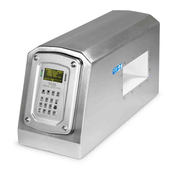
Industrial Metal Detectors
and Integrated Systems with Conveyor Belt
THS/21E - THS/21
Document
FI002K0018v1100UK
Read this manual carefully before installing, operating or carrying out maintenance on the device. Keep the manual in a
safe place for future reference and in perfect condition. This manual must accompany the device described herein in the
case of change of ownership and until the device is decommissioned.
FI002K0018v1100UK – THS/21 Instruction manual for installation, use and maintenance
Instruction manual
for installation, use
and maintenance
Date
2012-03-29
ORIGINAL INSTRUCTIONS
Hardware
HV5.xx
Software
THSV5401 – ALMV5400
1
Advertisement
Table of Contents


Need help?
Do you have a question about the THS/21E Series and is the answer not in the manual?
Questions and answers