Table of Contents
Advertisement
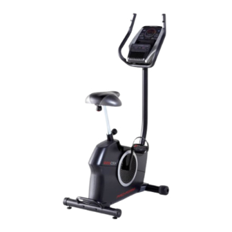
proform.com
Model No. PFEX52915.2
Serial No.
USER'S MANUAL
Write the serial number in the space
above for reference.
Serial Number
Decal
ACTIVATE YOUR
WARRANTY
To register your product and
activate your warranty today,
go to my.proform.com.
CUSTOMER CARE
For service at any time, go to
proformservice.com.
Or call 1-888-533-1333
Mon.–Fri. 6 a.m.–6 p.m. MT
Sat. 8 a.m.–12 p.m. MT
Please do not contact the store.
CAUTION
Read all precautions and
instructions in this manual before
using this equipment. Keep this
manual for future reference.
Advertisement
Table of Contents

Subscribe to Our Youtube Channel
Related Manuals for Pro-Form 225 CSX


Summary of Contents for Pro-Form 225 CSX
- Page 1 proform.com Model No. PFEX52915.2 Serial No. USER’S MANUAL Write the serial number in the space above for reference. Serial Number Decal ACTIVATE YOUR WARRANTY To register your product and activate your warranty today, go to my.proform.com. CUSTOMER CARE For service at any time, go to proformservice.com.
-
Page 2: Table Of Contents
TABLE OF CONTENTS WARNING DECAL PLACEMENT ............. . .2 IMPORTANT PRECAUTIONS . -
Page 3: Important Precautions
IMPORTANT PRECAUTIONS WARNING: To reduce the risk of serious injury, read all important precautions and instructions in this manual and all warnings on your exercise bike before using your exercise bike. ICON assumes no responsibility for personal injury or property damage sustained by or through the use of this product. - Page 4 STANDARD SERVICE PLANS...
-
Page 5: Before You Begin
The ance, and toning the body. The 225 CSX exercise bike model number and the location of the serial number provides an impressive selection of features designed decal are shown on the front cover of this manual. -
Page 6: Part Identification Chart
PART IDENTIFICATION CHART Use the drawings below to identify the small parts needed for assembly. The number in parentheses below each drawing is the key number of the part, from the PART LIST near the end of this manual. The number following the key number is the quantity needed for assembly. -
Page 7: Assembly
ASSEMBLY • To hire an authorized service technician to • In addition to the included tool(s), assembly assemble this product, call 1-800-445-2480. requires the following tools: one Phillips screwdriver • Assembly requires two persons. one standard screwdriver • Place all parts in a cleared area and remove the packing materials. - Page 8 2. Using a standard screwdriver, remove the Shield Cover (26) from the Left and Right Shields (37, 58). If there is a shipping tube (not shown) on the rear of the Frame (50), remove the screws from the shipping tube and discard the screws and 37, 58 the shipping tube.
- Page 9 4. Set the Seat Carriage (15) on the Seat Post (18) and hold it in place. Insert the Seat Knob (19) upward into the Seat Post (18), and tighten the Seat Knob into the Seat Bracket (14) inside the Seat Carriage (15). 5.
- Page 10 6. Tip: Avoid pinching the Main Wire (25). Orient the Upright (27) as shown, and hold it on the Frame (50). Attach the Upright (27) with four M8 x 20mm Screws (29); start all the Screws, and then tighten them. Avoid pinching the Main Wire (25) 7.
- Page 11 8. Orient the Shield Cover (26) as shown, and press it onto the Left and Right Shields (37, 58). 37, 58 9. Orient the Console Cover (3) as shown, and slide it onto the Upright (27). Tip: Avoid pinching the Main Wire (25). Insert the Handlebar (4) into the Upright (27).
- Page 12 10. Untie and discard the wire tie on the Main Wire (25). Route the Main Wire upward through the Handlebar (4) as shown. While a second person holds the Console (7) near the Handlebar (4), connect the wires (H) on the Console to the Main Wire (25) and the Pulse Wire (23).
- Page 13 13. Attach the Tablet Holder (1) to the Console (7) with four #8 x 5/8" Screws (8); start all the Screws, and then tighten them. 14. Identify the Right Pedal (60). Using an adjustable wrench, firmly tighten the Right Pedal (60) clockwise into the Right Crank Arm (59).
- Page 14 15. After the exercise bike is assembled, inspect it to make sure that it is assembled correctly, that it functions properly, and that all parts are properly tightened. Extra parts may be included. Place a mat under the exercise bike to protect the floor or carpet.
-
Page 15: How To Use The Exercise Bike
HOW TO USE THE EXERCISE BIKE HOW TO PLUG IN THE POWER ADAPTER HOW TO ADJUST THE HEIGHT OF THE SEAT IMPORTANT: If the exercise bike has been exposed For effective exercise, the seat should be at the proper to cold temperatures, allow it to warm to room tem- height. - Page 16 HOW TO ADJUST THE PEDAL STRAPS HOW TO USE THE TABLET HOLDER To adjust the IMPORTANT: The tablet holder (G) is designed for use with most full-size tablets. Do not place pedal straps, first any other electronic device or object in the tablet pull the ends of the straps (E) off holder.
- Page 17 CONSOLE DIAGRAM When you use the manual mode of the console, you can change the resistance of the pedals with the touch of a button. You can also create custom manual workouts with alternating high- and low-intensity intervals. As you exercise, the console will provide continu- ous exercise feedback.
- Page 18 HOW TO USE THE MANUAL MODE Note: After you press a button, it will take a moment for the pedals to reach the selected 1. Turn on the console. resistance level. 5. Do interval training, if desired. Begin pedaling or press any button on the console to turn on the console.
- Page 19 To set a power output target, press the Watts/ 7. Follow your progress with the display. Kg increase and decrease buttons until the desired power output target appears in the display. The display can show the following workout information: Note: After you set a power output target, the resistance level will automatically adjust to a preset Calories (CALS)—The approximate number of level.
- Page 20 Change the volume level of the When your pulse is detected, your heart rate will be console by pressing the Vol shown in the display. For the most accurate heart increase and decrease buttons. rate reading, hold the contacts for at least 15 seconds.
- Page 21 HOW TO USE AN ONBOARD WORKOUT At the end of each segment of the workout, a series of tones will sound. The resistance level 1. Turn on the console. for the next segment will appear in the display for a few seconds to alert you. The resistance of the Begin pedaling or press any button on the console pedals will then change.
- Page 22 5. Follow your progress with the display. HOW TO USE THE SOUND SYSTEM See step 7 on page 19. To play music or audio books through the console sound system while you exercise, plug a 3.5 mm male 6. Measure your heart rate if desired. to 3.5 mm male audio cable (not included) into the jack on the console and into a jack on your personal See step 8 on page 20.
- Page 23 THE OPTIONAL CHEST HEART RATE MONITOR 2. Connect your heart rate monitor to the console if desired. Whether your goal is to If you are connecting both your heart rate monitor and your tablet to the console, you must connect burn fat or to strengthen your your heart rate monitor before you connect...
- Page 24 HOW TO CONNECT YOUR HEART RATE MONITOR 3. Change settings as desired. TO THE CONSOLE Change the Unit of Measurement—The display The console is compatible with all BLUETOOTH Smart will alternate showing the console version number heart rate monitors. and the unit of measurement. To connect your BLUETOOTH Smart heart rate moni- The console can show tor to the console, press the iFit Sync button on the...
-
Page 25: Fcc Information
FCC INFORMATION This equipment has been tested and found to comply with the limits for a Class B digital device, pursuant to part 15 of the FCC Rules. These limits are designed to provide reasonable protection against harmful interference in a residential installation. This equipment generates, uses, and can radiate radio frequency energy and, if not installed and used in accordance with the instructions, may cause harmful interference to radio communications. -
Page 26: Maintenance And Troubleshooting
MAINTENANCE AND TROUBLESHOOTING MAINTENANCE HOW TO ADJUST THE REED SWITCH Regular maintenance is important for optimal If the console does not display correct feedback, the performance and to reduce wear. Inspect and properly reed switch should be adjusted. tighten all parts each time the exercise bike is used. Replace any worn parts immediately. - Page 27 HOW TO ADJUST THE DRIVE BELT Using an M10 socket wrench with an extension (not included), reach into the opening in the bottom of the If you can feel the pedals slip while you are pedaling, Right Shield (58) and tighten the M10 x 50mm Screw even when the resistance is adjusted to the highest (49) a few turns until the Drive Belt (not shown) is tight;...
-
Page 28: Exercise Guidelines
EXERCISE GUIDELINES Burning Fat—To burn fat effectively, you must exer- WARNING: cise at a low intensity level for a sustained period of Before beginning this time. During the first few minutes of exercise, your or any exercise program, consult your physi- body uses carbohydrate calories for energy. - Page 29 SUGGESTED STRETCHES The correct form for several basic stretches is shown at the right. Move slowly as you stretch; never bounce. 1. Toe Touch Stretch Stand with your knees bent slightly and slowly bend forward from your hips. Allow your back and shoulders to relax as you reach down toward your toes as far as possible.
-
Page 30: Part List
PART LIST Model No. PFEX52915.2 R0518A Key No. Qty. Description Key No. Qty. Description Tablet Holder Left Crank Arm M4 x 16mm Screw M4 x 19mm Self-tapping Screw Console Cover Left Shield Handlebar Snap Ring Handlebar Cap Bearing Pulse Sensor M4 x 12mm Screw Console Resistance Cable... -
Page 31: Exploded Drawing
EXPLODED DRAWING Model No. PFEX52915.2 R0518A... -
Page 32: Ordering Replacement Parts
ORDERING REPLACEMENT PARTS To order replacement parts, please see the front cover of this manual. To help us assist you, be prepared to provide the following information when contacting us: • the model number and serial number of the product (see the front cover of this manual) •...
Need help?
Do you have a question about the 225 CSX and is the answer not in the manual?
Questions and answers