Table of Contents
Advertisement
Quick Links
Introduction
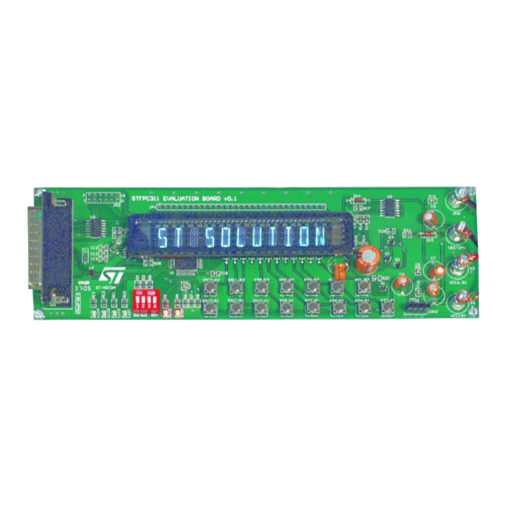
The STFPC311 is an evaluation board designed for quick and easy evaluation of STFPC311
Vacuum Fluorescent Display (VFD) Controller. The key features include:
17-segment, 11-digit VFD,
15 programmable Front Panel keys,
2 switches,
4 LEDs,
2 LEDs to display Standby and Mute status,
1 InfraRed (IR) Connector for remote control (RC),
Parallel Port for communication with PC,
External power supply to power up the controller and VFD Filament, and
STFPC311 Graphical User Interface (GUI) to demonstrate communication to the VFD
controller as it has been interfaced with a micro controller.
The evaluation board package includes:
1 STFPC311 board (see
STFPC311 GUI, and
User manual.
Figure 1.
March 2006
www.BDTIC.com/ST
Hardware Description and User Guide
Figure 1
STFPC311 Evaluation Board v0.1
STFPC311 Evaluation Board
),
Rev 1
UM0213
User Manual
1/25
www.st.com
Advertisement
Table of Contents

Related Manuals for ST STFPC311


Summary of Contents for ST STFPC311
-
Page 1: Figure 1. Stfpc311 Evaluation Board V0.1
STFPC311 Evaluation Board Hardware Description and User Guide Introduction The STFPC311 is an evaluation board designed for quick and easy evaluation of STFPC311 Vacuum Fluorescent Display (VFD) Controller. The key features include: 17-segment, 11-digit VFD, 15 programmable Front Panel keys,... -
Page 2: Table Of Contents
Getting Started ..........4 STFPC311 Demo Board Layout ....... . . 4 Software Installation . - Page 3 STFPC311 Evaluation (Demo) Board Layout ........
-
Page 4: Getting Started
(drives the VFD Controller), (drives other components, such as the transistor), and Figure 2 3 connectors with a common ground which are provided on the board (see STFPC311 Demo Board Layout Figure 2. STFPC311 Evaluation (Demo) Board Layout 4/25 www.BDTIC.com/ST... -
Page 5: Software Installation
Connecting the Board Plug the power supply group into the board (see Figure 3 Connect the parallel cable to the host system (see Figure 2 on page 4 Figure 3. Power Supply Connection VEE –24V VCC 3.3V VCC 12V AI12217 5/25 www.BDTIC.com/ST... -
Page 6: Starting The Demo Application
The “WATCHDOG ACTION SETTING” frame enables the user to program the time-out event which tells the VFD controller to either go into STANDBY mode or remain in its current state (“No Action”) by selecting the appropriate radio buttons (see Figure 5 Figure 4. Configure Parallel Port 6/25 www.BDTIC.com/ST... -
Page 7: Figure 5. Ready High Selection
UM0213 - User Manual Starting the Demo Application Figure 5. READY HIGH Selection 7/25 www.BDTIC.com/ST... -
Page 8: Command Tab
Starting the Demo Application UM0213 - User Manual COMMAND Tab 2.2.1 Configuring the Display Selecting the appropriate digits, segments, and dimming settings to configure the VFD (see Figure 6 Figure 6. COMMAND Tab for Display Configuration - Clicked ON 8/25 www.BDTIC.com/ST... -
Page 9: Write Display Memory Tab
UM0213 - User Manual Starting the Demo Application WRITE DISPLAY MEMORY Tab This tab allows the user to select the data to be seen on the VFD controller (see Figure 7 Figure 7. VFD Filament Data Display Selection 9/25 www.BDTIC.com/ST... -
Page 10: Returning To The Command Tab
One can select the time period after which the status of the Front Panel keys is to be read. The same option is also available for READ RC DATA (see Figure 8 ) and RTC STATUS (see Figure 10 on page 13 Figure 8. Command Tab Options 10/25 www.BDTIC.com/ST... -
Page 11: Rc And Hotkeys Config Tab
2.5.2 Device Address Setting The STFPC311 needs to be configured with the address of the Remote Control with which it is intended to be interfaced. Specify the address of the Remote Control in the text box in the “RC ADDRESS” frame on RC AND HOTKEYS CONFIG tab (see Figure 9 ). -
Page 12: Front Panel Hotkeys
The decoded IR commands are passed on to the main processor through the serial interface by sending 3 bytes of data. Labels in “READ RC DATA” frame on COMMAND tab represents the 24 bits of these 3-byte data frames. 12/25 www.BDTIC.com/ST... -
Page 13: Rtc Tab
Note: The color of IRQ label changes to green when the RTC interrupt is generated. Note: If “Read Date/Time” check box is selected, the Time display in “Time Settings” frame follows system time. Figure 10. Setting the Alarm Using the RTC 13/25 www.BDTIC.com/ST... -
Page 14: Appendix A Remote Control Protocols
3-byte data frame when the RC5 remote control STANDBY key is pressed. The RC key interpretation of these bit values for the 3-byte data frames for the various STFPC311 protocols is as follows: B1 to B5: Device Address B6: Start bit... -
Page 15: Rc5 Hot Key Configuration
UM0213 - User Manual Remote Control Protocols RC5 Hot Key Configuration Figure 12 shows the STFPC311 being configured to interface with the RC5 protocol-based remote control. The RC5 hot key addressing for STANDBY configuration is as follows: RC Address: 0x00... -
Page 16: Figure 13. Rc5 Protocol Standby Key Waveforms
IR sensor output when the RC5 STANDBY key is pressed. The output shown is an inversion of the IR signal received by the IR sensor. Figure 13. RC5 Protocol STANDBY Key Waveforms Toggle 5-bit Address 6-bit Command LSB MSB Start Bits AI12253 16/25 www.BDTIC.com/ST... -
Page 17: Rc6 Protocol Key Interpretation
IR sensor when STANDBY key of RC6 remote control is pressed. The RC key interpretation of these bit values for the 3-byte data frames for the various STFPC311 protocols is as follows: B1-B8: Device Address B9: Start bit... -
Page 18: Rc6 Hot Key Configuration
Remote Control Protocols UM0213 - User Manual RC6 Hot Key Configuration Figure 15 shows STFPC311 being configured to interface with the RC6 protocol-based remote control. The RC6 hot key addressing for the STANDBY configuration is as follows: RC Address: 0x27... -
Page 19: Figure 16. Rc6 Protocol Standby Key Waveforms
Figure 16. RC6 Protocol STANDBY Key Waveforms Address Data LSB MSB Mode 0 0 1 0 0 1 1 1 0 0 0 0 1 1 0 0 AI12254 Notes: 1. LS: Leader Start Pulse 2. SB: Start Bit 3. TR: Trailer Bit 19/25 www.BDTIC.com/ST... -
Page 20: Nec Protocol Key Interpretation
3 byte data frame when KEY1 of NEC remote is pressed. The RC key interpretation of these bit values for the 3-byte data frames for the various STFPC311 protocols is as follows: B1-B8: Device Address B9: Start bit... -
Page 21: Nec Hot Key Configuration
UM0213 - User Manual Remote Control Protocols NEC Hot Key Configuration Figure 18 shows STFPC311 being configured to interface with NEC protocol-based remote control. The NEC hot key addressing for the KEY1 configuration is as follows: RC Address: 0x02 Hot Key: KEY1 (code: 0x88) A command is transmitted only once, even when the key on the remote control remains pressed. -
Page 22: Figure 19. Nec Protocol Key1 Code Waveforms
IR sensor output when the NEC remote control KEY1 is pressed. The output shown is an inversion of the IR signal received by the IR sensor. Figure 19. NEC Protocol KEY1 Code Waveforms 22/25 www.BDTIC.com/ST... -
Page 23: Appendix B Front Panel Key Banks
Front Panel Key Banks Appendix B Front Panel Key Banks STFPC311 has key data memory of size 2x12, which means it can support up to 24 Front Panel keys. These keys are divided into 3 banks of 8 keys each. -
Page 24: Revision History
Revision History UM0213 - User Manual Revision History Table 2. Document Revision History Date Revision Changes 21-Mar-2006 Initial release. 24/25 www.BDTIC.com/ST... - Page 25 No license, express or implied, by estoppel or otherwise, to any intellectual property rights is granted under this document. If any part of this document refers to any third party products or services it shall not be deemed a license grant by ST for the use of such third party products or services, or any intellectual property contained therein or considered as a warranty covering the use in any manner whatsoever of such third party products or services or any intellectual property contained therein.
Need help?
Do you have a question about the STFPC311 and is the answer not in the manual?
Questions and answers