Advertisement
Quick Links
T echnical
Manual
Table of Contents
Specification.....................................1
Parts List ..........................................2~6
Adjustment.......................................7
Assembled View...............................8
PCB Assembly .................................9~10
Schematic Diagram..........................11~12
Specification
Continuous Power Output into 8 ohms
(20-20kHz, < 0.03% THD)
2
6x50 watts/ch into 8 ohms, all channel driven
Continuous Power Output into 4 ohms
(DIN 1 kHz,1.0% THD)
D
6x80 watts/ch into 4 ohms, all channels driven
Total Harmonic Distortion
o
(20Hz-20kHz, 8 ohms)
2
Continuous rated power. <0.03%
One-half rated power. <0.03%
1 watt power. <0.03%
Intermodulation Distortion
(60 Hz : 7 kHz, 4:1)
< 0.03%
Danping Factor
(20-20,000 Hz, 8 ohms)
>200
Input Impedance
20 k Ohms
Input Sensitivity
1.0 volt
Amplifier Gain:
26 dB
Input Overload Level
5.0 volt
Peak Current
> 25 A
Frequency Response (±1 dB)
10Hz-100kHz
BUNZAN-SHINSEN-BLD. 4F 10-10 SHINSEN-CHO, SHIBUYA-KU,
TOKYO 150-0045, JAPAN
Quality Uncompromised
®
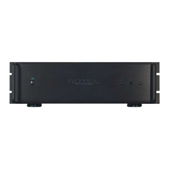
STEREO POWER AMPLIFIER
RKB-650
S/N Ratio (IHF A)
115 dB
Crosstalk/Separation
> 70 dB
Speaker Impedance
4 ohms minimum
Auto Turn On Level (with all inputs)
1 mV input signal
Power Requirements
USA: 120 Volts, 60 Hz
Europe: 230 Volts, 50 Hz
Power Consumption
450 Watts
Idle: 42 Watts
d
Standby: 2.6 Watts
Dimensions (W x H x D)
(not including rack adaptors)
n
430 x 144 x 429 mm
16.9 x 5.7 x 16.9 in
Weight (net)
15.5 kg, 34.1 lb.
Panel Height
3U, 132.6 mm/5.2 in
Serial. NO.
Y-382A-0505/pdf
Advertisement

Related Manuals for Rotel RKB-650


Summary of Contents for Rotel RKB-650
-
Page 1: Table Of Contents
Quality Uncompromised ® T echnical STEREO POWER AMPLIFIER RKB-650 Manual Table of Contents Specification........1 Parts List ..........2~6 Adjustment........7 Assembled View.......8 PCB Assembly .........9~10 Schematic Diagram......11~12 Specification Continuous Power Output into 8 ohms S/N Ratio (IHF A) (20-20kHz, < 0.03% THD) - Page 2 RKB-650 Appearance PROTECTION POWER SIX CHANNEL POWER AMPLIFIER RKB-650 LEVEL SIGNAL OUTPUT INPUT INPUT INPUT LINK SIGNAL SENSE LINK LINK 12V TRIG STEREO STEREO SPEAKERS C SPEAKERS B SPEAKERS A AC BREAKER RIGHT LEFT RIGHT LEFT RIGHT LEFT SPEAKER IMPEDANCE:...
-
Page 3: Parts List 1/4
RKB-650 Parts List 1/4 SYMBOL PARTS NO. DESCRIPTION 016 X-1425A01-04 PCB ASSY 501 X-1425 PCB ASS'Y (MAIN) L201,202,301,302,401,402 021 TRL-332 SPEAKER COIL 1Φ 23T T002 022 T-1101N01 SUB TRANSFORMER IC271,371,471 031 MPC1237HA IC (PROTECTION) IC101,102 031 NJM4558DD IC (OPE DUAL) - Page 4 RKB-650 Parts List 2/4 SYMBOL PARTS NO. DESCRIPTION S901 061 C-4176A08 POWER SW PS3-22SPA-P7AZ TV-8 (PCB) RY201,301,401 063 DG2SU-24 RELAY DG24D2-OS(M) RY901 063 OZT-SS-112LM1 RELAY DC 12V TV8 S201,301 064 4TR-2341 SLIDE SWITCH SSSU122NB1 (LINK) S701 064 C-4660A00 SLIDE SWITCH SS010-P823...
- Page 5 RKB-650 Parts List 3/4 SYMBOL PARTS NO. DESCRIPTION Q107,108,207,208 (Q307,308,407,408) 032 TC1941-KL TRANSISTOR 2SC1941-T-KL Q151,152,251,252 (Q351,352,451,452) 032 TC536-FG TRANSISTOR 2SC536KAA-FG Q111-114,211-214 (Q311-314,411-414) 033 B631-EF TRANSISTOR 2SB631K-EF Q115,116,215,216 (Q315,316,415,416) 033 D600-EF TRANSISTOR 2SD600K-EF D101-104,151,152 (D301-304,351,352) 034 T1N4148-86 DIODE 1N4148TAP-50 D201-204,251,252 (D401-404,451,452)
- Page 6 RKB-650 Parts List 4/4 SYMBOL PARTS NO. DESCRIPTION 019 4TR-2823#2 PLASTIC FOOT 24Φ (ABS) 019 4TSH-19#2 PLASTIC FOOT 50Φ (BLACK) 019 VF4-19A00 HOLE RUBBER PLUG for RACK FRAME 019 VF4-20A00 HOLE RUBBER PLUG for FRONT PANEL 022 T-1099N01 POWER TRANSFORMER...
-
Page 7: Adjustment
RKB-650 Adjustment Instruments : DC milli-meter Notes : Prior to Bias Adjustment, run about 5minutes with rated output (8 ohms) And warm up Power Transistor and Heat Sink.Set input off. Step Coupling Location Adjust for Adjust X-1427-00 PCB R533 or R535... -
Page 8: Assembled View
RKB-650 Assembled View 501 E-1434 501 X-1425-02 BROWN K101B K201B K301B WHITE K701B K702B K205B K305B K204B K405B K304B K404B D00A D00B D00C K403B CON8 K203B K701A K702A K202B2 K303B K204A CH-C K202B1 CH-A K502B1 501 X-1425-01 K504A K502B2 RED RED BLK... -
Page 9: Pcb Assembly 1/2
RKB650 / RMB1048 PCB Assembly 1/2 016 X-1334B01 - 02 016 E-1434A00... - Page 10 RKB-650 PCB Assembly 2/2 016 X-1425A00...
-
Page 11: Schematic Diagram 1/2
Schematic Diagram 1/2 016 E-1427A00, 016 X-1334B01 - 02, 016 X-1425A02, 03, 04 RKB650... - Page 12 RKB-650 Schematic Diagram 2/2 016 X-1425A01,02 ,016 E-1434...
Need help?
Do you have a question about the RKB-650 and is the answer not in the manual?
Questions and answers